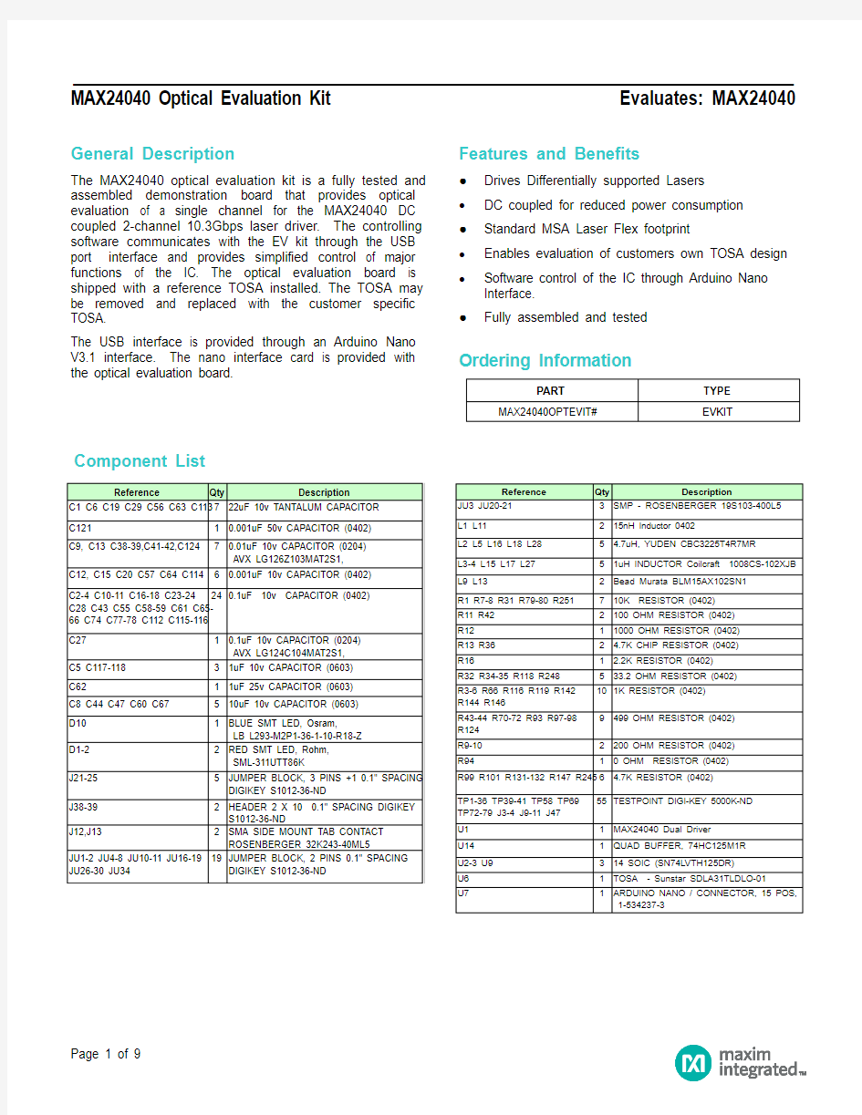

General Description
The MAX24040 optical evaluation kit is a fully tested and assembled demonstration board that provides optical evaluation of a single channel for the MAX24040 DC coupled 2-channel 10.3Gbps laser driver. The controlling software communicates with the EV kit through the USB port interface and provides simplified control of major functions of the IC. The optical evaluation board is shipped with a reference TOSA installed. The TOSA may be removed and replaced with the customer specific TOSA.
The USB interface is provided through an Arduino Nano V3.1 interface. The nano interface card is provided with the optical evaluation board. Features and Benefits
●Drives Differentially supported Lasers
?DC coupled for reduced power consumption
●Standard MSA Laser Flex footprint
?Enables evaluation of customers own TOSA design ?Software control of the IC through Arduino Nano Interface.
●Fully assembled and tested
Ordering Information
Component List
Quick Start
Required Equipment
?MAX24040 Optical Eval Kit
? 3.3v, 500mA supply
?Optical patch cable LC/FC
?O/E converter (86105C)
?Scope Mainframe (86100D)
?Optical Attenuator (prevents possible overload of O/E converter)
?Pattern Generator
?Matched SMA cable set
?Lap Top w GUI installed
Warning: Invisible light radiation from optical subassembly (TOSA) may cause damage to eye. Avoid looking directly at TOSA output or output from LC/PC fiber.
Procedure
?Verify shunts are installed on JU1, JU2, JU19, JU30 and JU34 for desired power distribution.
?Connect pattern generator data outputs to SMA data inputs on EVKIT using a matched cable set. Set data output levels to between 0.25 and 0.5v p-p.
?Carefully install LC optical connector into TOSA provided. Secure fiber to PCB with small piece of tape to provide strain relief.
?Connect other end of patch cable into O/E converter. An optical attenuator may be required to prevent the O/E converter from overload.
?Preset power supply to 3.3v with 500mA current limit. Turn off supply then connect to VCC location on EVKIT.
?Connect USB cable from Lap Top to Arduino interface. (Arduino is powered from USB)
?Turn on power supply.
?Copy file folder from CD ROM onto LapTop and Activate GUI
?The following screen should appear.
?Press Connect to access the Optical Evaluation board
?Default values should appear in some of the register locations as seen below.
?At the top left of the screen select File then open.
?Select and Open the GUI configuration file contained on the provided CD ROM drive. This file contains the settings for the specific TOSA provided with the optical evaluation board.
?
The correct settings for the TOSA provided will now appear in the GUI registers.
Settings
1
2
3 4
5
7
6
Use Setup mode to make adjustments
This Screen Tab selected below (STAT) contains the status bits.
Output Eye from TOSA sample provided with EVKIT
_________________________________________________________________ MAX24040 Optical Evaluation Kit Evaluates: MAX24040
Layer 1 Top and 6 Bottom superimposed
Revision History
Layer 2, Ground
DESCRIPTION
PAGES CHANGED
—
PCB = 6 layers total