TECHNICAL DATA
ILE4264-2
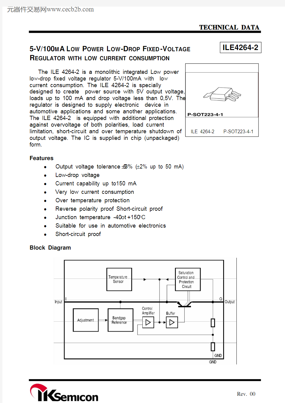
5-V/100M A L OW P OWER L OW -D ROP F IXED -V OLTAGE R EGULATOR WITH LOW CURRENT CONSUMPTION
ILE 4264-2 P-SOT223-4-1
The ILE 4264-2 is a monolithic integrated Low power low-drop fixed voltage regulator 5-V/100mA with low current consumption. The ILE 4264-2 is specially
designed to create power source with 5V output voltage, loads up to 100 mA and drop voltage less than 0,5V. The regulator is designed to supply electronic device in automotive applications and some another applications. The ILE 4264-2 is equipped with additional protection against overvoltage of both polarities, load current limitation, short-circuit and over temperature shutdown of
output voltage. The IC is supplied in chip (unpackaged) form.
Features
? Output voltage tolerance 5±3% (±2% up to 50 mA) ? Low-drop voltage
? Current capability up to150 mA ? Very low current consumption ? Over temperature protection
? Reverse polarity proof Short-circuit proof ? Junction temperature -40 t о +150°С
? Suitable for use in automotive electronics ? Short-circuit proof
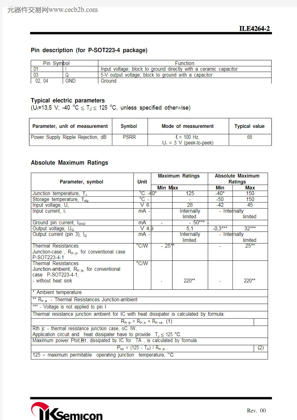
Block Diagram
Pin description (for P-SOT223-4 package)
Pin Symbol Function 01 I Input voltage; block to ground directly with a ceramic capacitor 03 Q 5-V output voltage; block to ground with a capacitor 02, 04 GND Ground
Typical electric parameters
(U I =13,5 V, -40 o C ≤ T J ≤ 125 o C, unless specified otherwise)
Parameter, unit of measurement Symbol Mode of measurement Typical value
Power Supply Ripple Rejection, dB
PSRR
f r = 100 Hz,
U r = 3 V (peek-to-peek)
68
Absolute Maximum Ratings
Maximum Ratings
Absolute Maximum
Ratings
Parameter, symbol
Unit Min Max Min Max
Junction temperature, ТJ o
C -40* 125 -40* 150 Storage temperature, Тstg o
C - - -50 150 Input voltage, U I V 6 28 -42 45
Input current, I I
mA - Internally limited - Internally
limited
Ground pin current, I GND mA - - 50*** - Output voltage, U Q
V 4,9 5,1 -0,3*** 32*** Output current (pin 3), I Q
mA - Internally limited - Internally
limited
Thermal Resistances
Junction-case , R th jc , for conventional case P-SOT223-4-1
o
C/W - 25** - 25**
Thermal Resistances
Junction-ambient, R th ja , for conventional case P-SOT223-4-1, - without heat sink
o
C/W
-
220** -
220**
* Ambient temperature
** R th ja - Thermal Resistances Junction-ambient *** - Voltage is not applied to pin I
Thermal resistance junction ambient for IC with heat dissipater is calculated by formula:
R th ja = R th jc + R th ca , (1)
Rth jc - thermal resistance junction case, oC /W.
Application circuit and heat dissipater have to provide T J ≤ 125 o С.
Maximum power Ptot,Вт, dissipated by IC for TA , is calculated by formula:
P tot = (125 - T A ) / R th ja , (2)
125 – maximum permitable operating junction temperature, ОС
Electric parameters (U I =13,5 V, -40 o C ≤ T J ≤ 125 o C, unless specified otherwise)
Typical value
Parameter, unit of measurement
Symbol Mode of measurement Min Max
Note
9 V ≤ U I ≤ 16 V 5 mA ≤ I Q ≤ 50 mA 4,9 5,1 Output voltage, V
U Q
6 V ≤ U I ≤ 21 V 5 mA ≤ I Q ≤ 100 mA 4,85 5,15 Maximum output current, mA I Qmax 4,8 V ≤ U Q ≤ 5,2 V 150 500 I Q =0,1 mA, (T J ≤ 85o C)
- 0,06 I Q = 0,1 mA - 0,07 Consumption current, mA, I q = I I - I Q
I q I Q = 50 mA - 4 Drop-out voltage, V U Dr I Q = 100 mA - 0,5 1
Load regulation, mV ΔU Q(I) 1 mA ≤ I Q ≤ 100 mA
U I = 13,5 V - 90 Line regulation, mV
ΔU Q(U)
6 V ≤ U I ≤ 28V I Q = 1 mA
- 30
Notes
1 Drop voltage U Dr = U I - U Q (measured when the output voltage V Q has dropped 100 mV from the nominal value obtained at V I = 13.5 V).
ILE4264-2 Application Circuit
Typical Performance Characteristics
Package Dimensions P-SOT 223-4-1