DW 143
Table 1Ductwork Classification and Air Leakage Limits Positive (Pa)Negativ e (Pa)
Low-pressure -
Class A 50050010Medium-Pressue -Class B 100075020High-Pressure -
Class C
200075040Where P is the differential, pressure in Pa
Example
Design Pressure =
1000Pa Area Size of AHU=100m2
Maximum leakage of Ductwork according classB = 0.009 x P^0.65 (LPS / m^2)
Q/A=0.009 *1000^0.65LPS/m2
=0.8021258LPS/m2
Total Maximum leakage flow rate=80.2126LPS
BS EN1886-1998
5.1.1. Units operating under negative pressure
Unless otherwise specified, the applicable rate shall be a function of the efficiency of the air filters within the
air handling unit. Where there is more than one stage of air filtration, the classification shall be based on the
efficiency of the highest grade of filter
Table 2Casing air leakage classes for air handling unit, 400 Pa negative test pressure
Leakage class Max.leakage LPS/m2Filter Class (EN779)3A 3.96G1-4
A 1.32F5-7
B 0.44F8-9
5.1.2. Units operating under both negative pressure and positive pressue
Air handling units with sections operating under positive pressure shall have the positive pressure
sections tested separately from the rest of the unit in all cases where the operating pressure immediately
downstream of the fan exceeds 250 Pa positive. If the positive pressure does not exceed 250 Pa, a single,
combined negative pressure test shall be acceptable. The test pressure applied to the positive pressure
sections shall be 700 Pa positive, or the air handling unit's maximum positive operating pressure, whichever
is the greater. The remainder of the unit shall be tested in accordance with 5.1.1, the applicable leakage rate
being governed by the efficiency of the filter immediately upstream of the fan.
The air leakage from the sections subjected to 700 Pa positive pressure shall be in accordance with Table 3
Table 3Casing air leakage classes for air handling unit, 700 Pa positive test pressure
Leakage class Max.leakage LPS/m23A 5.7
A 1.9
B 0.63
In the case of units tested at a higher pressure than 700 Pa the maximum allowable leakage rate for
each leakage class shall be calculated from the following formula
fm = f700 * (test pressure / 700) ^ 0.65
fm is the maximum allowable leakage at actual test pressure (LPS/m2)
f700 is the maximum allowable leakage at 700 Pa pressure from Table 3 above (LPS/m2)
Example
Equip. Tag
Number
Section Pressure Lengh M Width M Height M Area M2Design TSP mmH2O Design Pa Test Pa Leakage rate LPS/m2Total Leakage LPS Total Leakage CMH MAU
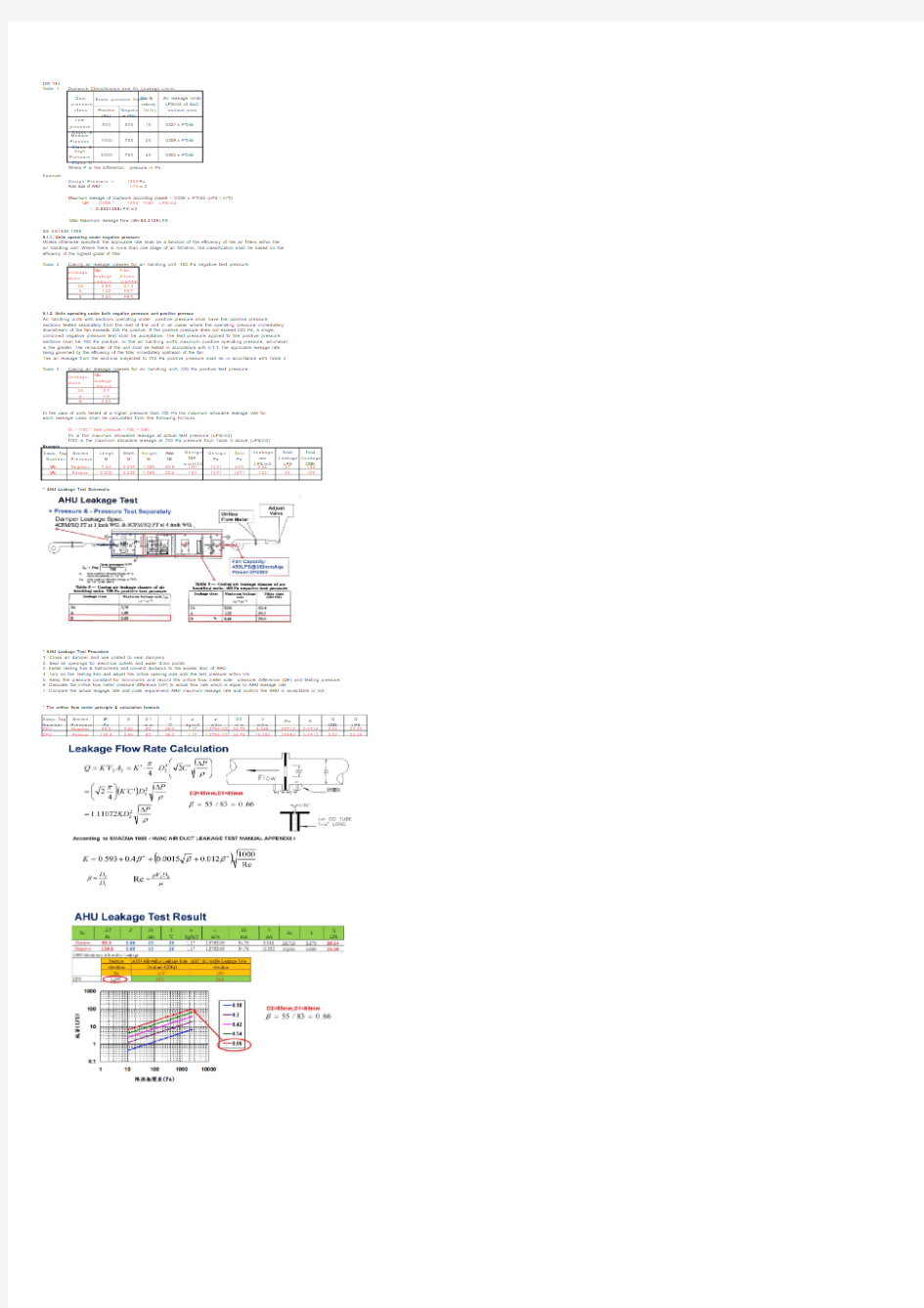
Negative 7.44 3.335 1.58583.815014714000.4437133MAU Positive 2.235 3.335 1.58532.615014711471 1.0233120* AHU Leakage Test Schematic
* AHU Leakage Test Procedure
1. Close all damper and use plated to seal dampers
2. Seal all openings for electrical outlets and water drain points.
3. Install Testing Fan & Instruments and connect ductwork to the access door of AHU
4. Turn on the Testing Fan and adjust the orifice opening size until the test pressure within 5%.
5. Keep the pressure constant for 5minmums and record the orifice flow meter side pressure difference (DP) and testing pressure
6. Calculate the orifice flow meter pressure difference (DP) to actual flow rate which is equal to AHU leakage rate
7. Compare the actual leagage rate and code requirement AHU maximum leakage rate and confirm the AHU is acceptable or not. * The orifice flow meter principle & calculation formula
Equip. Tag
Number Section Pressure ΔP Pa βD1mm T °C ρkg/m2νm2/s D2mm V m2/s Re K Q CMS Q LPS CFU
Negative 95.30.668328.0 1.17 1.576E-0554.788.548297120.67160.0220.20CFU Positive 139.80.668328.0 1.17 1.576E-0554.7810.352359820.67130.0224.460.027 x P^0.65
0.009 x P^0.65
0.003 x P^0.65Air leakage limits LPS/m2 of duct surface area
Duct
pressure
class Static pressure limit Maxi. Air velocity (m/s)