元器件交易网https://www.doczj.com/doc/1d11374659.html,
Contents
Features (1)
Applications (1)
Pin Assignment (1)
Block Diagram (1)
Selection Guide (2)
Absolute Maximum Ratings (2)
Electrical Characteristics (3)
Test Circuits (11)
Technical Terms (12)
Operation (13)
Transient Response (14)
Standard Circuit (17)
Application Circuits (17)
Notes on Design (19)
Dimensions (20)
Markings (20)
Package Power Dissipation (21)
Taping Dimensions (22)
Characteristics (25)
Measuring Circuits (31)
Frequently Asked Question s (32)
Seiko Instruments Inc.1
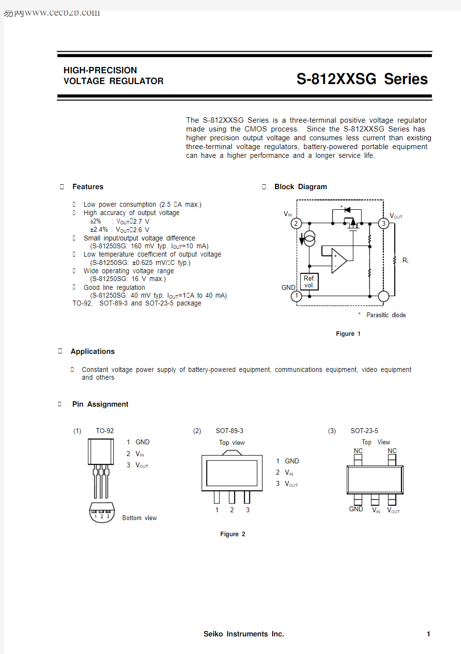
The S-812XXSG Series is a three-terminal positive voltage regulator made using the CMOS process. Since the S-812XXSG Series has higher precision output voltage and consumes less current than existing three-terminal voltage regulators, battery-powered portable equipment can have a higher performance and a longer service life.
Applications
Constant voltage power supply of battery-powered equipment, communications equipment, video equipment
and others
Pin Assignment
HIGH-PRECISION
VOLTAGE REGULATOR
S-812XXSG Series
Features
Low power consumption (2.5 A max.) High accuracy of output voltage
±2% : V OUT 2.7 V ±2.4% : V OUT 2.6 V
Small input/output voltage difference
(S-81250SG: 160 mV typ. I OUT =10 mA) Low temperature coefficient of output voltage
(S-81250SG: ±0.625 mV/ C typ.) Wide operating voltage range
(S-81250SG: 16 V max.) Good line regulation
(S-81250SG: 40 mV typ. I OUT =1 A to 40 mA) T O-92, SOT-89-3 and SOT-23-5 package
Block Diagram
Figure 1
R L
GND
V IN
V OUT
2
+-
*
Ref.vol.
3
1
* Parasitic diode
Bottom view
123
(1)
TO-92
1GND 2V IN 3V OUT
Top view
1
231GND 2V IN 3V OUT
(2)
SOT-89-3GND
V IN V OUT
NC NC
Top View (3)
SOT-23-5Figure 2
HIGH PRECISION VOLTAGE REGULATOR S-812XXSG Series
2Seiko Instruments Inc.
Selection Guide
Table 1
Output voltage TO-92 *1
SOT-89-3 *2
SOT-23-5 *21.1 2.4%S-81211SGY-X S-81211SGUP-DQA-X S-81211SG-QA-X 1.5 2.4%S-81215SGY-X
S-81215SGUP-DQK-X
S-81215SG-QK-X 1.7 2.4%S-81217SG-QQ-X 1.8 2.4%S-81218SG-QR-X 2.0 2.4%S-81220SGY-X S-81220SGUP-DQS-X S-81220SG-QS-X 2.1 2.4%S-81221SGUP-DQU-X 2.3 2.4%S-81223SGY-X S-81223SG-QW-X 2.4 2.4%S-81224SGY-X S-81224SGUP-DQX-X S-81224SG-QX-X 2.5 2.4%S-81225SGY-X S-81225SGUP-DQH-X S-81225SG-QH-X 2.7 2.0%S-81227SGUP-DQZ-X 3.0 2.0%S-81230SGY-X S-81230SGUP-DQB-X S-81230SG-QB-X 3.3 2.0%S-81233SGY-X S-81233SGUP-DQF-X S-81233SG-QF-X 3.5 2.0%S-81235SGY-X S-81235SGUP-DQI-X S-81235SG-QI-X 3.6 2.0%S-81236SGUP-DQ7-X 3.7 2.0%S-81237SGY-X S-81237SGUP-DQE-X S-81237SG-QE-X 4.0 2.0%S-81240SGY-X S-81240SGUP-DQJ-X S-81240SG-QJ-X 4.2 2.0%S-81242SG-IB-X 4.5 2.0%S-81245SGY-X S-81245SGUP-DQ5-X S-81245SG-Q5-X 4.6 2.0%S-81246SGY-X S-81246SGUP-DQM-X S-81246SG-QM-X 4.7 2.0%S-81247SG-IE-X 5.0 2.0%S-81250SGY-X S-81250SGUP-DQD-X S-81250SG-QD-X 5.2 2.0%S-81252SGY-X
S-81252SGUP-DQL-X S-81252SG-QL-X
5.3 2.0%S-81253SGUP-DIJ-X 5.4 2.0%S-81254SGUP-DIK-X 5.5 2.0%S-81255SGUP-DIL-X 5.6 2.0%
S-81256SGUP-DIM-X
*
1In the TO-92 package, “x” differs depending upon the packaging form:
B : Loose T, Z : Tape
*
2In the SOT package, “x” differs depending upon the packaging form (in the SOT-23-5 package, on-tape packed products only):
S : Stick
T : Tape (T1 and T2 are available depending upon the direction of the IC)
Absolute Maximum Ratings
Table 2
(Unless otherwise specified: Ta=25 C)
Parameter
Symbol Conditions Ratings Unit V OUT 2.6 V 12V Input voltage V IN V OUT 2.7 V
18
Output voltage V OUT V IN +0.3 to V SS -0.3
V Output current I OUT 100mA TO-92400Power dissipation P D SOT-89-3500mW SOT-23-5
150Operating temperature T opr -40 to +85 C Storage temperature
T stg
-40 to +125
C
Caution: Keep static electricity to a minimum.
HIGH-PRECISION VOLTAGE REGULATOR
S-812XXSG Series
Seiko Instruments Inc.3
Electrical Characteristics
1.
S-81211SGY-X, S-81211SGUP-DQA-X, S-81211SG-QA-X (1.1-V output type)
Parameter Symbol Conditions
Min.Typ.Max.Unit Test cir.
Output voltage V OUT V IN =1.5 V, I OUT =0.5 mA 1.073 1.100 1.127V 1I/O voltage difference V dif I OUT =0.5 mA 0.050.2V 1Line regulation 1 V OUT 1V IN =1.5 to 10 V I OUT =0.5 mA 1050mV 1Line regulation 2 V OUT 2V IN =1.5 to 10 V I OUT =10 A
1077mV 1Load regulation V OUT 3V IN =1.5 V
I OUT =10 A to 0.5 mA 10100mV 1Current consumption I SS V IN =1.5 V, Unloaded
1.2
2.5 A 2Input voltage V IN 10V Temperature charac-teristic of V OUT
V OUT Ta
V IN =1.5 V, I OUT = 0.5 mA Ta=-40 C to 85 C
±0.138
mV/ C
2. S-81215SGY-X, S-81215SGUP-DQK-X, S-81215SG-QK-X (1.5-V output type)
Parameter Symbol Conditions
Min.Typ.Max.Unit Test cir.
Output voltage V OUT V IN =3.5 V, I OUT =0.5 mA 1.464 1.500 1.536V 1I/O voltage difference V dif I OUT =0.5 mA 0.030.18V 1Line regulation 1 V OUT 1V IN =2.5 to 10 V I OUT =0.5 mA 739mV 1Line regulation 2 V OUT 2V IN =2.5 to 10 V I OUT =1 A
7105mV 1Load regulation V OUT 3V IN =3.5 V
I OUT =1 A to10 mA 80120mV 1Current consumption I SS V IN =3.5 V, Unloaded
1.2
2.5 A 2Input voltage V IN 10V Temperature charac-teristic of V OUT
V OUT Ta
V IN =3.5 V, I OUT = 0.5 mA Ta=-40 C to 85 C
±0.188
mV/ C
3. S-81217SG-QQ-X (1.7-V output type)
Parameter Symbol Conditions
Min.Typ.Max.Unit Test cir.
Output voltage V OUT V IN =3.7 V, I OUT =10 mA 1.659 1.700 1.741V 1I/O voltage difference V dif I OUT =10 mA 0.77 1.63V 1Line regulation 1 V OUT 1V IN =2.7 to 10 V I OUT =1 mA 843mV 1Line regulation 2 V OUT 2V IN =2.7 to 10 V I OUT =1 A
8119mV 1Load regulation V OUT 3V IN =3.7 V
I OUT =1 A to 10 mA 80120mV 1Current consumption I SS V IN =3.7 V, Unloaded
1.2
2.5 A 2Input voltage V IN 10V Temperature charac-teristic of V OUT
V OUT Ta
V IN =3.7 V, I OUT = 10 mA Ta=-40 C to 85 C
±0.213
mV/ C
Table 3
(Unless otherwise specified: Ta=25 C)
Table 4
(Unless otherwise specified: Ta=25 C)
Table 5
(Unless otherwise specified: Ta=25 C)
HIGH PRECISION VOLTAGE REGULATOR S-812XXSG Series
4Seiko Instruments Inc.
4.
S-81218SG-QR-X (1.8-V output type)
Parameter Symbol Conditions
Min.Typ.Max.Unit Test cir.
Output voltage V OUT V IN =3.8 V, I OUT =10 mA 1.756 1.800 1.843V 1I/O voltage difference V dif I OUT =10 mA 0.72 1.55V 1Line regulation 1 V OUT 1V IN =2.8 to 10 V I OUT =1 mA 845mV 1Line regulation 2 V OUT 2V IN =2.8 to 10 V I OUT =1 A
8126mV 1Load regulation V OUT 3V IN =3.8 V
I OUT =1 A to 10 mA 80120mV 1Current consumption I SS V IN =3.8 V, Unloaded
1.2
2.5 A 2Input voltage V IN 10V Temperature charac-teristic of V OUT
V OUT Ta
V IN =3.8 V, I OUT = 10 mA Ta=-40 C to 85 C
±0.225
mV/ C
5.S-81220SGY-X, S-81220SGUP-DQS-X, S-81220SG-QS-X (2.0-V output type)
Parameter Symbol Conditions
Min.Typ.Max.Unit Test cir.
Output voltage V OUT V IN =4.0 V, I OUT =10 mA 1.592 2.000 2.048V 1I/O voltage difference V dif I OUT =10 mA 0.63 1.39V 1Line regulation 1 V OUT 1V IN =3.0 to 10 V I OUT =1 mA 848mV 1Line regulation 2 V OUT 2V IN =3.0 to 10 V I OUT =1 A
8140mV 1Load regulation V OUT 3V IN =4.0 V
I OUT =1 A to 10 mA 80120mV 1Current consumption I SS V IN =4.0 V, Unloaded
1.2
2.5 A 2Input voltage V IN 10V Temperature charac-teristic of V OUT
V OUT Ta
V IN =4.0 V, I OUT = 10 mA Ta=-40 C to 85 C
±0.250
mV/ C
6.S-81221SGUP-DQU-X (2.1-V output type)
Parameter Symbol Conditions
Min.Typ.Max.Unit Test cir.
Output voltage V OUT V IN =4.1 V, I OUT =10 mA 2.049 2.100 2.151V 1I/O voltage difference V dif I OUT =10 mA 0.59 1.32V 1Line regulation 1 V OUT 1V IN =3.1 to 10 V I OUT =1 mA 950mV 1Line regulation 2 V OUT 2V IN =3.1 to 10 V I OUT =1 A
9147mV 1Load regulation V OUT 3V IN =4.1 V
I OUT =1 A to 10 mA 80120mV 1Current consumption I SS V IN =4.1 V, Unloaded
1.2
2.5 A 2Input voltage V IN 10V Temperature charac-teristic of V OUT
V OUT Ta
V IN =4.1 V, I OU T = 10 mA Ta=-40 C to 85 C
±0.263
mV/ C
Table 6
(Unless otherwise specified : Ta=25 C)
Table 7
(Unless otherwise specified : Ta=25 C)
Table 8
(Unless otherwise specified : Ta=25 C)
HIGH-PRECISION VOLTAGE REGULATOR
S-812XXSG Series
Seiko Instruments Inc.5
7.
S-81223SGY-X, S-81223SG-QW-X (2.3-V output type)
Parameter Symbol Conditions
Min.Typ.Max.Unit Test cir.
Output voltage V OUT V IN =4.3 V, I OUT =10 mA
2.244 2.300 2.356V 1I/O voltage difference V dif IOUT =10 mA
0.53 1.20V 1Line regulation 1 V OUT 1V IN =3.3 to 10 V I OUT =1 mA 954mV 1Line regulation 2 V OUT 2V IN =3.3 to 10 V I OUT =1 A
9161mV 1Load regulation V OUT 3V IN =4.3 V
I OUT =1 A to 10 mA 80120mV 1Current consumption I SS V IN =4.3 V, Unloaded
1.2
2.5 A 2Input voltage V IN 10V Temperature charac-teristic of V OUT
V OUT Ta
V IN =4.3 V, I OUT = 10 mA Ta=-40 C to 85 C
±0.288
mV/ C
8.S-81224SGY-X, S-81224SGUP-DQX-X, S-81224SG-QX-X (2.4-V output type)
Parameter Symbol Conditions
Min.Typ.Max.Unit Test cir.
Output voltage V OUT V IN =4.4 V, I OUT =10 mA 2.342 2.400 2.458V 1I/O voltage difference V dif I OUT =10 mA 0.49 1.15V 1Line regulation 1 V OUT 1V IN =3.4 to 10 V I OUT =1 mA 1055mV 1Line regulation 2 V OUT 2V IN =3.4 to 10 V I OUT =1 A
10168mV 1Load regulation V OUT 3V IN =4.4 V
I OUT =1 A to 10 mA 80120mV 1Current consumption I SS V IN =4.4 V, Unloaded
1.2
2.5 A 2Input voltage V IN 10V Temperature charac-teristic of V OUT
V OUT Ta
V IN =4.4 V, I OUT = 10 mA Ta=-40 C to 85 C
±0.300
mV/ C
9.S-81225SGY-X, S-81225SGUP-DQH-X, S-81225SG-QH-X (2.5-V output type)
Parameter Symbol Conditions
Min.Typ.Max.Unit Test cir.
Output voltage V OUT V IN =4.5 V, I OUT =10 mA 2.440 2.500 2.560V 1I/O voltage difference V dif I OUT =10 mA 0.59 1.32V 1Line regulation 1 V OUT 1V IN =3.5 to 10 V I OUT =1 mA 1057mV 1Line regulation 2 V OUT 2V IN =3.5 to 10 V I OUT =1 A
10175mV 1Load regulation V OUT 3V IN =4.5 V
I OUT =1 A to 10 mA 80120mV 1Current consumption I SS V IN =4.5 V, Unloaded
1.2
2.5 A 2Input voltage V IN 10V Temperature charac-teristic of V OUT
V OUT Ta
V IN =4.5 V, I OUT = 10 mA Ta=-40 C to 85 C
±0.313
mV/ C
Table 9
(Unless otherwise specified : Ta=25 C)Table 10
(Unless otherwise specified : Ta=25 C)
Table 11
(Unless otherwise specified : Ta=25 C)
HIGH-PRECISION VOLTAGE REGULATOR S-812XXSG Series
6Seiko Instruments Inc.
10.S-81227SGUP-DQZ-X (2.7-V output type)
Parameter Symbol Conditions
Min.Typ.Max.Unit Test cir.
Output voltage V OUT V IN =4.7 V, I OUT =10 mA 2.646 2.700 2.754V 1I/O voltage difference V dif I OUT =10 mA 0.52 1.20V 1Line regulation 1 V OUT 1V IN =3.7 to 16 V I OUT =1 mA 3672mV 1Line regulation 2 V OUT 2V IN =3.7 to 16 V I OUT =1 A
36189mV 1Load regulation V OUT 3V IN =4.7 V
I OUT =1 A to 20 mA 80120mV 1Current consumption I SS V IN =4.7 V, Unloaded
1.2
2.5 A 2Input voltage V IN 16V Temperature charac-teristic of V OUT
V OUT Ta
V IN =4.7 V, I OUT = 10 mA Ta=-40 C to 85 C
±0.338
mV/ C
11.S-81230SGY-X, S-81230SGUP-DQB-X, S-81230SG-QB-X (3.0-V output type)
Parameter Symbol Conditions
Min.Typ.Max.Unit Test cir.Output voltage V OUT V IN =5.0 V, I OUT =10 mA 2.940 3.000 3.060V 1I/O voltage difference V dif I OUT =10 mA 0.44 1.04V 1Line regulation 1 V OUT 1V IN =4.0 to 16 V I OUT =1 mA 3978mV 1Line regulation 2 V OUT 2V IN =4.0 to 16 V I OUT =1 A
39210mV 1Load regulation V OUT 3V IN =5 V
I OUT =1 A to 20 mA 60100mV 1Current consumption I SS V IN =5.0 V, Unloaded
1.2
2.5 A 2Input voltage V IN 16V Temperature charac-teristic of V OUT
V OUT Ta
V IN =5.0 V, I OUT = 10 mA Ta=-40 C to 85 C
±0.375
mV/ C
12.S-81233SGY-X, S-81233SGUP-DQF-X, S-81233SG-QF-X (3.3-V output type)
Parameter Symbol Conditions
Min.Typ.Max.Unit Test cir.Output voltage V OUT V IN =5.3 V, I OUT =10 mA 3.234 3.300 3.366V 1I/O voltage difference V dif I OUT =10 mA 0.370.91V 1Line regulation 1 V OUT 1V IN =4.3 to 16 V I OUT =1 mA 4284mV 1Line regulation 2 V OUT 2V IN =4.3 to 16 V I OUT =1 A
42231mV 1Load regulation V OUT 3
V IN =5.3 V
I OUT =1 A to 20 mA 60100mV 1Current consumption I SS V IN =5.3 V, Unloaded
1.2
2.5 A 2Input voltage V IN 16V Temperature charac-teristic of V OUT
V OUT Ta
V IN =5.3 V, I OUT = 10 mA Ta=-40 C to 85 C
±0.413
mV/ C
Table 12
(Unless otherwise specified : Ta=25 C)
Table 13
(Unless otherwise specified : Ta=25 C)
Table 14
(Unless otherwise specified : Ta=25 C)
HIGH-PRECISION VOLTAGE REGULATOR
S-812XXSG Series
Seiko Instruments Inc.7
13.S-81235SGY-X, S-81235SGUP-DQI-X, S-81235SG-QI-X (3.5-V output type)
Parameter Symbol Conditions
Min.Typ.Max.Unit Test cir.Output voltage V OUT V IN =5.5 V, I OUT =10 mA 3.430 3.500 3.570V 1I/O voltage difference V dif I OUT =10 mA 0.340.84V 1Line regulation 1 V OUT 1V IN =4.5 to 16 V I OUT =1 mA 4488mV 1Line regulation 2 V OUT 2V IN =4.5 to 16 V I OUT =1 A
44245mV 1Load regulation V OUT 3
V IN =5.5 V
I OUT =1 A to 30 mA 60100mV 1Current consumption I SS V IN =5.5 V, Unloaded
1.2
2.5 A 2Input voltage V IN 16V Temperature charac-teristic of V OUT
V OUT Ta
V IN =5.5 V, I OUT = 10 mA Ta=-40 C to 85 C
±0.438
mV/ C
14. S-81236SGUP-DQ7-X (3.6-V output type)
Parameter Symbol Conditions
Min.Typ.Max.Unit Test cir.Output voltage V OUT V IN =5.6 V, I OUT =10 mA 3.528 3.600 3.672V 1I/O voltage difference V dif I OUT =16 mA 0.320.81V 1Line regulation 1 V OUT 1V IN =4.6 to 16 V I OUT =1 mA 4590mV 1Line regulation 2 V OUT 2V IN =4.6 to 16 V I OUT =1 A
45252mV 1Load regulation V OUT 3
V IN =5.6 V
I OUT =1 A to 30 mA 60100mV 1Current consumption I SS V IN =5.6 V, Unloaded
1.2
2.5 A 2Input voltage V IN 16V Temperature charac-teristic of V OUT
V OUT Ta
V IN =5.6 V, I OUT = 10 mA Ta=-40 C to 85 C
±0.450
mV/ C
15.S-81237SGY-X, S-81237SGUP-DQE-X, S-81237SG-QE-X (3.7-V output type)
Parameter Symbol Conditions
Min.Typ.Max.Unit Test cir.Output voltage V OUT V IN =5.7 V, I OUT =10 mA 3.626 3.700 3.774V 1I/O voltage difference V dif I OUT =10 mA 0.310.78V 1Line regulation 1 V OUT 1V IN =4.7 to 16 V I OUT =1 mA 4692mV 1Line regulation 2 V OUT 2V IN =4.7 to 16 V I OUT =1 A
46259mV 1Load regulation V OUT 3V IN =5.7 V
I OUT =1 A to 30 mA 60100mV 1Current consumption I SS V IN =5.7 V, Unloaded
1.2
2.5 A 2Input voltage V IN 16V Temperature charac-teristic of V OUT
V OUT Ta
V IN =5.7 V, I OUT = 10 mA Ta=-40 C to 85 C
±0.463
mV/ C
Table 15
(Unless otherwise specified : Ta=25 C)
Table 17
(Unless otherwise specified : Ta=25 C)
Table 16
(Unless otherwise specified : Ta=25 C)
HIGH-PRECISION VOLTAGE REGULATOR S-812XXSG Series
8Seiko Instruments Inc.
16.S-81240SGY-X, S-81240SGUP-DQJ-X, S-81240SG-QJ-X (4.0-V output type)
Parameter Symbol Conditions
Min.Typ.Max.Unit Test cir.Output voltage V OUT V IN =6.0 V, I OUT =10 mA 3.920 4.000 4.080V 1I/O voltage difference V dif I OUT =10 mA 0.270.70V 1Line regulation 1 V OUT 1V IN =5.0 to 16 V I OUT =1 mA 4896mV 1Line regulation 2 V OUT 2V IN =5.0 to 16 V I OUT =1 A
48280mV 1Load regulation V OUT 3V IN =6.0 V
I OUT =1 A to 30 mA 5090mV 1Current consumption I SS V IN =6.0 V, Unloaded
1.2
2.5 A 2Input voltage V IN 16V Temperature charac-teristic of V OUT
V OUT Ta
V IN =6.0 V, I OUT = 10 mA Ta=-40 C to 85 C
±0.500
mV/ C
17. S-81242SG-IB-X (4.2-V output type)
Parameter Symbol Conditions
Min.Typ.Max.Unit Test cir.Output voltage V OUT V IN =6.2V, I OUT =10 mA 4.116 4.200 4.284V 1I/O voltage difference V dif I OUT =10 mA 0.240.65V 1Line regulation 1 V OUT 1V IN =5.2 to 16 V I OUT =1 mA 50100mV 1Line regulation 2 V OUT 2V IN =5.2 to 16 V I OUT =1 A
50294mV 1Load regulation V OUT 3V IN =6.2 V
I OUT =1 A to 30 mA 5090mV 1Current consumption I SS V IN =6.2 V, Unloaded
1.2
2.5 A 2Input voltage V IN 16V Temperature charac-teristic of V OUT
V OUT Ta
V IN =6.2 V, I OUT = 10 mA Ta=-40 C to 85 C
±0.525
mV/ C
18.S-81245SGY-X, S-81245SGUP-DQ5-X, S-81245SG-Q5-X (4.5-V output type)
Parameter Symbol Conditions
Min.Typ.Max.Unit Test cir.Output voltage V OUT V IN =6.5 V, I OUT =10 mA 4.410 4.500 4.590V 1I/O voltage difference V dif I OUT =10 mA 0.210.58V 1Line regulation 1 V OUT 1V IN =5.5 to 16 V I OUT =1 mA 52104mV 1Line regulation 2 V OUT 2V IN =5.5 to 16 V I OUT =1 A
52315mV 1Load regulation V OUT 3V IN =6.5 V
I OUT =1 A to 30 mA 5090mV 1Current consumption I SS V IN =6.5 V, Unloaded
1.2
2.5 A 2Input voltage V IN 16V Temperature charac-teristic of V OUT
V OUT Ta
V IN =6.5 V, I OUT = 10 mA Ta=-40 C to 85 C
±0.563
mV/ C
Table 18
(Unless otherwise specified : Ta=25 C)
Table 20
(Unless otherwise specified : Ta=25 C)Table 19
(Unless otherwise specified : Ta=25 C)
HIGH-PRECISION VOLTAGE REGULATOR
S-812XXSG Series
Seiko Instruments Inc.9
19.S-81246SGY-X, S-81246SGUP-DQM-X, S-81246SG-QM-X (4.6-V output type)
Parameter Symbol Conditions
Min.Typ.Max.Unit Test cir.Output voltage V OUT V IN =6.6 V, I OUT =10 mA 4.508 4.600 4.692V 1I/O voltage difference V dif I OUT =10 mA 0.200.57V 1Line regulation 1 V OUT 1V IN =5.6 to 16 V I OUT =1 mA 53105mV 1Line regulation 2 V OUT 2V IN =5.6 to 16 V I OUT =1 A
53322mV 1Load regulation V OUT 3V IN =6.6 V
I OUT =1 A to 30 mA 5090mV 1Current consumption I SS V IN =6.6 V, Unloaded
1.2
2.5 A 2Input voltage V IN 16V Temperature charac-teristic of V OUT
V OUT Ta
V IN =6.6 V, I OUT = 10 mA Ta=-40 C to 85 C
±0.575
mV/ C
20.S-81247SG-IE-X (4.7-V output type)
Parameter Symbol Conditions
Min.Typ.Max.Unit Test cir.Output voltage V OUT V IN =6.7 V, I OUT =10 mA 4.606 4.700 4.794V 1I/O voltage difference V dif I OUT =10 mA 0.190.55V 1Line regulation 1 V OUT 1V IN =5.7 to 16 V I OUT =1 mA 54107mV 1Line regulation 2 V OUT 2V IN =5.7 to 16 V I OUT =1 A
54329mV 1Load regulation V OUT 3V IN =6.7 V
I OUT =1 A to 30 mA 5090mV 1Current consumption I SS V IN =6.7 V, Unloaded
1.2
2.5 A 2Input voltage V IN 16V Temperature charac-teristic of V OUT
V OUT Ta
V IN =6.7 V, I OUT = 10 mA Ta=-40 C to 85 C
±0.588
mV/ C
21.S-81250SGY-X, S-81250SGUP-DQD-X, S-81250SG-QD-X (5.0-V output type)
Parameter Symbol Conditions
Min.Typ.Max.Unit Test cir.Output voltage V OUT V IN =7.0 V, I OUT =10 mA 4.900 5.000 5.100V 1I/O voltage difference V dif I OUT =10 mA 0.160.50V 1Line regulation 1 V OUT 1V IN =6.0 to 16 V I OUT =1 mA 55110mV 1Line regulation 2 V OUT 2V IN =6.0 to 16 V I OUT =1 A
55350mV 1Load regulation V OUT 3V IN =7.0 V
I OUT =1 A to 40 mA 4080mV 1Current consumption I SS V IN =7.0 V, Unloaded
1.2
2.5 A 2Input voltage V IN 16V Temperature charac-teristic of V OUT
V OUT Ta
V IN =7.0 V, I OUT = 10 mA Ta=-40 C to 85 C
±0.625
mV/ C
Table 21
(Unless otherwise specified : Ta=25 C)Table 22
(Unless otherwise specified : Ta=25 C)Table 23
(Unless otherwise specified : Ta=25 C)
HIGH-PRECISION VOLTAGE REGULATOR S-812XXSG Series
10Seiko Instruments Inc.
22.S-81252SGY-X, S-81252SGUP-DQL-X, S-81252SG-QL-X (5.2-V output type)
Parameter Symbol Conditions
Min.Typ.Max.Unit Test cir.Output voltage V OUT V IN =7.2 V, I OUT =10 mA 5.096 5.200 5.304V 1I/O voltage difference V dif I OUT =10 mA 0.150.47V 1Line regulation 1 V OUT 1V IN =6.2 to 16 V I OUT =1 mA 57113mV 1Line regulation 2 V OUT 2V IN =6.2 to 16 V I OUT =1 A
57364mV 1Load regulation V OUT 3V IN =7.2 V
I OUT =1 A to 40 mA 4080mV 1Current consumption I SS V IN =7.2 V, Unloaded
1.2
2.5 A 2Input voltage V IN 16V Temperature charac-teristic of V OUT
V OUT Ta
V IN =7.2 V, I OUT = 10 mA Ta=-40 C to 85 C
±0.650
mV/ C
23.S-81253SGUP-DIJ-X (5.3-V output type)
Parameter Symbol Conditions
Min.Typ.Max.Unit Test cir.Output voltage V OUT V IN =7.3 V, I OUT =10 mA 5.194 5.300 5.406V 1I/O voltage difference V dif I OUT =10 mA 0.140.45V 1Line regulation 1 V OUT 1V IN =6.3 to 16 V I OUT =1 mA 57114mV 1Line regulation 2 V OUT 2V IN =6.3 to 16 V I OUT =1 A
57371mV 1Load regulation V OUT 3V IN =7.3 V
I OUT =1 A to 40 mA 4080mV 1Current consumption I SS V IN =7.3 V, Unloaded
1.2
2.5 A 2Input voltage V IN 16V Temperature charac-teristic of V OUT
V OUT Ta
V IN =7.3 V, I OUT = 10 mA Ta=-40 C to 85 C
±0.663
mV/ C
24.S-81254SGUP-DIK-X (5.4-V output type)
Parameter Symbol Conditions Min.Typ.Max.Unit Test cir.Output voltage V OUT V IN =7.4 V, I OUT =10 mA
5.292 5.400 5.508V 1I/O voltage difference V dif I OUT =10 mA 0.130.44V 1Line regulation 1 V OUT 1V IN =
6.4 to 16 V I OUT =1 mA 58115mV 1Line regulation 2 V OUT 2V IN =6.4 to 16 V I OUT =1 A 58378mV 1Load regulation V OUT 3V IN =
7.4 V
I OUT =1 A to 40 mA 4080mV 1Current consumption
I SS V IN =7.4 V, Unloaded
1.2
2.5 A 2Input voltage V IN 16V Temperature charac-teristic of V OUT
V OUT Ta
V IN =7.4 V, I OUT = 10 mA Ta=-40 C to 85 C
±0.675
mV/ C
Table 24
(Unless otherwise specified : Ta=25 C)
Table 25
(Unless otherwise specified : Ta=25 C)
Table 26
(Unless otherwise specified : Ta=25 C)
HIGH-PRECISION VOLTAGE REGULATOR
S-812XXSG Series
Seiko Instruments Inc.11
25.S-81255SGUP-DIL-X (5.5-V output type)
Parameter Symbol Conditions Min.Typ.Max.Unit Test cir.Output voltage V OUT V IN =7.5 V, I OUT =10 mA
5.390 5.500 5.610V 1I/O voltage difference V dif I OUT =10 mA 0.130.43V 1Line regulation 1 V OUT 1V IN =
6.5 to 16 V I OUT =1 mA 58116mV 1Line regulation 2 V OUT 2V IN =6.5 to 16 V I OUT =1 A 58385mV 1Load regulation V OUT 3V IN =
7.5 V
I OUT =1 A to 40 mA 4080mV 1Current consumption
I SS V IN =7.5 V, Unloaded
1.2
2.5 A 2Input voltage V IN 16V Temperature charac-teristic of V OUT
V OUT Ta
V IN =7.5 V, I OUT = 10 mA Ta=-40 C to 85 C
±0.688
mV/ C
26.S-81256SGUP-DIM-X (5.6-V output type)
Parameter Symbol Conditions Min.Typ.Max.Unit Test cir.Output voltage V OUT V IN =7.6 V, I OUT =10 mA
5.488 5.600 5.712V 1I/O voltage difference V dif I OUT =10 mA 0.120.42V 1Line regulation 1 V OUT 1V IN =
6.6 to 16 V I OUT =1 mA 59117mV 1Line regulation 2 V OUT 2V IN =6.6 to 16 V I OUT =1 A 59392mV 1Load regulation V OUT 3V IN =
7.6 V
I OUT =1 A to 40 mA 4080mV 1Current consumption
I SS V IN =7.6 V, Unloaded
1.2
2.5 A 2Input voltage V IN 16V Temperature charac-teristic of V OUT
V OUT Ta
V IN =7.6 V, I OUT = 10 mA Ta=-40 C to 85 C
±0.7
mV/ C
Test Circuits
Table 27
(Unless otherwise specified : Ta=25 C)Table 28
(Unless otherwise specified : Ta=25 C)
Figure 3
GND
GND
V IN V OUT
V IN
V OUT
1
2
S-812XXSG Series
V V
A
V
A
S-812XXSG Series
HIGH-PRECISION VOLTAGE REGULATOR
S-812XXSG Series
Technical Terms
1Output voltage (V OUT)
The precision of output voltage is guaranteed at ±2.0% or ±2.4% under the prescribed conditions of input voltage, output voltage, and temperature, which differ with items. If these conditions are varied, output voltage value may change into beyond the scope of precision of output voltage. See electrical characteristics and characteristics
data for detail.
2Line regulations 1 and 2 ( V OUT1, V OUT2)
Indicates the input voltage dependencies of output voltage. That is, the values express how the output voltage changes, when input voltage is changed under the condition that output current is fixed.
3Load regulation ( V OUT3)
Indicates the output current dependencies of output voltage. That is, the values express how the output voltage changes, when output current is changed under the condition that input voltage is fixed.
4I/O voltage defference (V dif)
98% of V OUT is output when the voltage of V OUT+V dif is applied. When V dif is small, output keeps a constant
voltage in the small side of input voltage and large output current can be obtained.
NOTE : V dif is highly dependent on I OUT.
12Seiko Instruments Inc.
HIGH-PRECISION VOLTAGE REGULATOR
S-812XXSG Series
Seiko Instruments Inc.13
Operation
1
Basic operation
Figure 4 shows the block diagram of the S-812XXSG Series.The error amplifier compares a reference voltage V REF with a part of the output voltage fed back by the feedback resistors R A and R B . It supplies the control transistor with the gate current, necessary to keep a stable output voltage range not influenced by input voltage or temperature fluctuation.
V IN
Error amplifier
R B
R A
Current source
-+
V OUT
GND
*
Reference voltage circuit
* Parasitic diode
Figure 4 Reference block diagram
2Internal circuit
2.1Reference voltage circuit
In a voltage regulator, the reference voltage circuit plays a very important role because any change will show up directly at an output.
The S-812XXSG Series has 0.8 V typical stable voltage circuit as a highly stable reference voltage source.Features:
Low power consumption
Good temperature characteristic
2.2Error amplifier
The error amplifier consumes very low current because it is a differential amplifier in a stable current circuit.Features:
Good matching characteristics Wide operating voltage range Low offset voltage
2.3Control transistor
The S-812XXSG Series has a Pch MOS transistor as a current control transistor shown in Figure 6. Therefore an output current I OUT is expressed by the following formula where is only a small difference between input and output voltages:
I OUT =KP{2(V GS -V TP ) (V IN -V OUT )-(V IN -V OUT )2
}*KP :Conductive coefficiency
V TP :Threshold voltage of a control transistor Setting KP to the large value results in a voltage regulator with 160 mV typical I/O voltage difference.
V IN -
V IN +
GND
V IN
V OUT
Figure 5 Error amplifier
Bias
V IN
V OUT
GND
V GS
V REF -+
*
* Parasitic diode
Figure 6 Control transistor
NOTE :A parasitic diode is generated between V IN and V OUT .
If the electric potential of V IN is higher than that of V OUT , IC may break because of a reverse current.Keep V OUT less than V IN +0.3 V.
HIGH-PRECISION VOLTAGE REGULATOR S-812XXSG Series
14Seiko Instruments Inc.
3
Temperature characteristic of output voltage
The temperature characteristic of the output voltage is expressed by the following formula in the range of -40 C to 85 C.
*V REF is 0.7 V min., 0.8 V typ., 0.9 V max.
Transient Response
1.
Line transient response
The overshoot and undershoot are caused in the output voltage if the input voltage fluctuates while the output current is constant. Figure 7 shows the output voltage fluctuation due to input voltage change between 6.0 V and 10 V in square wave. Table 19 shows the parameter dependency when input voltage fluctuates. For reference,Figure 8 describes the measurement circuit.
Table 29 Parameter dependency due to input voltage fluctuation
Parameter
Method to decrease
overshoot
Method to decrease
undershoot
Output current
I OUT
Decrease Decrease Load capacitance C L Increase Increase Input voltage fluctuation V IN *
Decrease
Decrease Temperature
Ta
High temperature
*
V IN : High voltage value - low voltage value
For reference, the next page describes the results of measuring the ringing amounts at the V OUT pin using the
output current (I OUT ), load capacitance (C L ), input voltage fluctuation width ( V IN ), and temperature as parameters.
V REF
V OUT x (±0.1) mV/ C typ.
Figure 7 Output voltage fluctuation due to input voltage fluctuation
Input voltage
6.0
10 V
Undershoot
Overshoot
Output voltage
Figure 8 Measuring circuit
Fast amplifier
P.G.
S-812XXSG
Oscilloscope
C L
V OUT
V SS
V IN
+-
HIGH-PRECISION VOLTAGE REGULATOR
S-812XXSG Series
Seiko Instruments Inc.15
- 2.Load transient response
The overshoot and undershoot are caused in the output voltage if the output current fluctuates while the input
voltage is costant. Figure 9 shows the output voltage fluctuation due to output current change between 10mA and 1 A in square wave. Table 20 shows the parameter dependency when output current fluctuates. For reference,Figure 10 describes the measuring circuit.
Line transient response of S-81250SG
Reference data
1.I OUT dependency
C L =10 F Ta=25 C
1.2
1.00.80.6
0.40.20.00
51015202530
Ringing amount
(V)
I OUT (mA)
2.C L dependency
Undershoot Overshoot
I OUT =10mA Ta=25 C
1.21.0
0.80.6
0.40.2
0.00
Ringing amount
(V)
1020304050
C L ( F)
4.Temperature dependency
Undershoot Overshoot
I OUT =10mA C L =10 F
1.21.0
0.80.6
0.40.20.0Ringing amount
(V)
80
400
-40
Ta ( C)
3. V IN dependency
V IN shows the difference between the low voltage fixed to 6 V and the high voltage.
For example, V IN = 2 V means the difference between 6 V and 8 V. 1.2
1.00.80.6
0.40.20.0
Ringing amount
(V)
1
2
4
5
V IN (V)
3
C L =10 F Ta=25 C
I OUT =10mA
Figure 9 Output voltage fluctuation due to output current fluctuation
Output current
10mA
1 A
Output voltage
Overshoot
Undershoot
Figure 10 Measuring circuit
S-812XXSG
Oscilloscope
C L
V OUT V SS
V IN
HIGH-PRECISION VOLTAGE REGULATOR S-812XXSG Series
16Seiko Instruments Inc.
Table 28 Parameter dependency due to output current fluctuation Parameter
Method to decrease
overshoot
Method to decrease
undershoot
Output current fluctuation I OUT Decrease Decrease Load capacitance C L Increase Increase Input voltage V IN Increase Increase Temperature
Ta
For reference, the following describes the results of measuring the ringing amounts at the V OUT pin using the input voltage (V IN ), load capacitance (C L ), output current fluctuation width ( I OUT ), and temperature as parameters.
Load transient response of S-81250SG
Reference data
2.C L dependency
V IN =7V Ta=25 C
0.50.4
0.30.2
0.1
0.0
010********
C L ( F)
Ringing amount (V)
3. I OUT dependency I OUT shows the difference between the low current fixed to 1 A and the high.
For example, I OUT =10 mA means the difference between 10mA and 1 A.
C L =10 F Ta=25 C
V IN =7V
1.2
1.00.80.60.4
0.20.0
5
1015202530 I OUT (mA)
Ringing amount
(V)
4.Temperature dependency
Undershoot Overshoot
V IN =7V
C L =10 F
0.50.4
0.30.2
0.10
4080
-40
Ta ( C)
Ringing amount (V)
1.V IN dependency
0.6
0.50.4
0.30.2
0.10.0
6
8
101214
16
Ringing
amount (V)
V IN (V)
C L =10 F Ta=25 C
HIGH-PRECISION VOLTAGE REGULATOR
S-812XXSG Series
Seiko Instruments Inc.17
Standard Circuit
The basic circuit using the S-812XXSG Series is shown in Figure 11.
Application Circuits
1.
High output current positive voltage regulator
Single-point GND
Common
Common
C O
C I
V OUT
V IN
3
21
S-812XXSG Series Figure 11
Figure 12 shows a circuit for increasing the output current.
Short-circuit protection of Tr1 is possible by adding the sense resistor R S and the PNP transistor as shown in Figure 13.
R
Tr1
GND
V OUT
V IN V IN
V OUT
Common
Figure 12
S-812XXSG Series
GND
Rs R
V IN Tr2Tr1
V IN
V OUT
Common
S-812XXSG
Series
Figure 13
HIGH-PRECISION VOLTAGE REGULATOR S-812XXSG Series
18Seiko Instruments Inc.
2.
Circuits for increasing output voltage
3.Constant current regulator
4.Dual supply
If the output voltage you need cannot be found in our product line-up, the designs in Figures 14 or 15 will increase output voltages easily.
V OUT =Vxx 1121221
R R Iss R Vxx R R Because of its low current consumption, the
S-812XXSG Series can set the resistor values, and R 1and R 2 high to lower the power consumption of whole systems.
Current flows to the Zener diode (Di) through the
quiescent current (I SS ) of the S-812XXSG Series, and the GND terminal rises for the voltage of DI.
When Di cannot drive with a quiescent current, the added resistance R increases the current flowing through DI.
GND
V OUT
I SS
R 2
R 1
V OUT
V IN V IN V XX
S-812XXSG Series Figure 14
Di GND R
I SS
V OUT
V OUT
V IN
V IN S-812XXSG Series Figure 15
The S-812XXSG Series can be used as a constant-current regulator within allowable dissipation limits.
I OUT =
V XX R A
+ I SS
I OUT
R L
GND
V XX
GND
I SS
R A
V OUT
V IN V IN S-812XXSG Series
Figure 16 Constant current regulator A dual supply can be formed using the S-812XXSG Series.
Figure 17 shows a circuit example for receiving two outputs (5 V and 8 V) with the S-81230SG and the S-81250SG. As the resistance R lets the quiescent current of IC1 pass, R is unnecessary if the minimum output current of IC2 is more than the IC1 quiescent current.
V OUT 2GND
GND
GND
IC2
IC
V OUT
V OUT
+5 V
+8 V V OUT 1V IN
V IN
R V IN S-81230SG
S-81250SG Figure 17 Dual power source
HIGH-PRECISION VOLTAGE REGULATOR
S-812XXSG Series
Seiko Instruments Inc.19
Notes on Design
Voltage regulators may oscillate if small or zero capacity is connected to IC input when the impedance of the
power source is high and a large capacity is connected to IC output. The S-812XXSG Series has no short-current circuit limiting. The element may break by exceed current of
errorneous short-current. Keep the output current more than 10 A when using the product of V OUT 2.6 V under the condition of high input
voltage and high temperature. Do not apply any ripple voltage under the condition in Figure 18 to V IN terminal.
Mount diodes for IC protection, when connecting another power supply to V OUT terminal.
When designing for mass production using an application circuit described here, keep the deviation of components
and temperature characteristic.
Figure 18
f
V PP
V [V]
f [Hz]
V PP 0.5 V f 1000 Hz V OUT
OUT
GND
V IN
V / R
Figure 19