
LC877478C LC877472C LC877464C LC877456C
Overview
The LC877478C/72C/64C/56C are 8-bit single chip microcontrollers with the following on-chip functional blocks : ? CPU : operable at a minimum bus cycle time of 100ns
? On-chip ROM Maximum Capacity : LC877478C 80K-bytes
LC877472C 72K-bytes LC877464C 64K-bytes LC877456C 56K-bytes ? On-chip RAM capacity : 2048-bytes ? LCD controller/driver
? 16-bit timer/counter (can be divided into 8-bit timer)
? 16-bit timer (can be divided into 8-bit timer, 8-bit timer can be PWM) ? Four 8-bit timer with prescalers ? Timer for use as date/time clock
? Synchronous serial I/O port (with automatic block transmit/receive function) ? Asynchronous/synchronous serial I/O port ? 15-channel × 8-bit AD converter ? Small signal detector ? High-speed clock counter ? System clock divider
? 20-source 10-vectored interrupt system
CMOS IC
FROM 80K/72K/64K/56K-byte, RAM 2048-byte on chip
8-bit 1-chip Microcontroller
Features
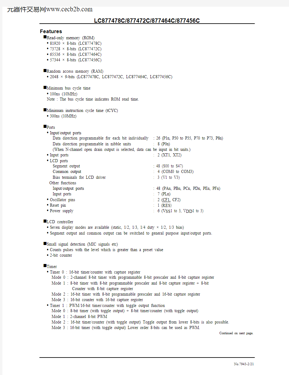
■Read-only memory (ROM)
? 81920 × 8-bits (LC877478C)
? 73728 × 8-bits (LC877472C)
? 65536 × 8-bits (LC877464C)
? 57344 × 8-bits (LC877456C)
■Random access memory (RAM)
? 2048 × 9-bits (LC877478C, LC877472C, LC877464C, LC877456C)
■Minimum bus cycle time
? 100ns (10MHz)
Note : The bus cycle time indicates ROM read time.
■Minimum instruction cycle time (tCYC)
? 300ns (10MHz)
■Ports
? Input/output ports
Data direction programmable for each bit individually : 26 (P1n, P30 to P35, P70 to P73, P8n)
Data direction programmable in nibble units : 8 (P0n)
(When N-channel open drain output is selected, data can be input in bit units.)
? Input ports : 2 (XT1, XT2)
? LCD ports
Segment output : 48 (S00 to S47)
Common output : 4 (COM0 to COM3)
Bias terminals for LCD driver : 3 (V1 to V3)
Other functions
Input/output ports : 48 (PAn, PBn, PCn, PDn, PEn, PFn)
Input ports : 7 (PLn)
? Oscillator pins : 2 (CF1, CF2)
? Reset pin : 1 (RES)
? Power supply : 6 (V SS1 to 3, V DD1 to 3)
■LCD controller
? Seven display modes are available (static, 1/2, 1/3, 1/4 duty × 1/2, 1/3 bias)
? Segment output and common output can be switched to general purpose input/output ports.
■Small signal detection (MIC signals etc)
? Counts pulses with the level which is greater than a preset value
? 2-bit counter
■Timer
? Timer 0 : 16-bit timer/counter with capture register
Mode 0 : 2-channel 8-bit timer with programmable 8-bit prescaler and 8-bit capture register
Mode 1 : 8-bit timer with 8-bit programmable prescaler and 8-bit capture register + 8-bit
Counter with 8-bit capture register
Mode 2 : 16-bit timer with 8-bit programmable prescaler and 16-bit capture register
Mode 3 : 16-bit counter with 16-bit capture register
? Timer 1 : PWM/16-bit timer/counter with toggle output function
Mode 0 : 8-bit timer (with toggle output) + 8-bit timer/counter (with toggle output)
Mode 1 : 2-channel 8-bit PWM
Mode 2 : 16-bit timer/counter (with toggle output) Toggle output from lower 8-bits is also possible.
Mode 3 : 16-bit timer (with toggle output) Lower order 8-bits can be used as PWM.
Continued on next page.
Continued from preceding page.
? Timer 4 : 8-bit timer with 6-bit prescaler
? Timer 5 : 8-bit timer with 6-bit prescaler
? Timer 6 : 8-bit timer with 6-bit prescaler
? Timer 7 : 8-bit timer with 6-bit prescaler
? Base Timer
1. The clock signal can be selected from any of the following :
Sub-clock (32.768kHz crystal oscillator), system clock, and prescaler output from timer 0
2. Interrupts of five different time intervals are possible.
■High speed clock counter
? Countable up to 20MHz clock (when using 10MHz main clock)
? Real time output
■Serial interface
? SIO0 : 8-bit synchronous serial interface
1. LSB first/MSB first is selectable
2. Internal 8-bit baud-rate generator (fastest clock period 4/3 tCYC)
3. Consecutive automatic data communication (1 to 256-bits)
? SIO1 : 8-bit asynchronous/synchronous serial interface
Mode 0 : Synchronous 8-bit serial I O (2-wire or 3-wire, transmit clock 2 to 512 tCYC)
Mode 1 : Asynchronous serial I O (half duplex, 8 data bits, 1 stop bit, baud-rate 8 to 2048 tCYC)
Mode 2 : Bus mode 1 (start bit, 8 data bits, transmit clock 2 to 512 tCYC)
Mode 3 : Bus mode 2 (start detection, 8 data bits, stop detection)
■AD converter
? 8-bits × 15-channels
■Remote control receiver circuit (connected to P73/INT3/T0IN terminal)
? Noise rejection function (noise rejection filter’s time constant can be selected from 1/32/128 tCYC)
■Watchdog timer
? The watching time period is determined by an external RC.
? Watchdog timer can produce interrupt or system reset
■Interrupts : 20 sources, 10 vectors
1. Three priority (low, high and highest) multiple interrupts are supported.
During interrupt handling, an equal or lower priority interrupt request is postponed.
2. If interrupt requests to two or more vector addresses occur at once, the higher priority interrupt takes
precedence. In the case of equal priority levels, the vector with the lowest address takes precedence.
No. Vector Selectable Level Interrupt Signal
1 00003H X or L INT0
2 0000BH X or L INT1
L INT2/T0L/INT4
3 00013H H
or
4 0001BH H or L INT3/Base timer/INT5
L T0H
5 00023H H
or
L T1L/T1H
6 0002BH H
or
L SIO0
or
7 00033H H
or
L SIO1
8 0003BH H
or
L ADC/MIC/T6/T7
9 00043H H
10 0004BH H or L Port 0/T4/T5
? Priority Level : X>H>L
? For equal priority levels, vector with lowest address takes precedence.
■Subroutine stack levels : 2048 levels max. Stack is located in RAM.
■Multiplication and division
? 16-bit × 8-bit (executed in 5 cycles)
? 24-bit × 16-bit (12 cycles)
? 16-bit ÷ 8-bit (8 cycles)
? 24-bit ÷ 16-bit (12 cycles)
■Oscillation circuits
? On-chip RC oscillation for system clock use.
? CF oscillation for system clock use. (Rf built in, Rd external)
? Crystal oscillation low speed system clock use. (Rf built in, Rd external)
? On-chip frequency variable RC oscillation circuit for system clock use.
■System clock divider
? Low power consumption operation is available
? Minimum instruction cycle time 300ns, 600ns, 1.2μs, 2.4μs, 4.8μs, 9.6μs, 19.2μs, 38.4μs, 76.8μs can be switched by program (when using 10MHz main clock)
■Standby function
? HALT mode
HALT mode is used to reduce power consumption. During the HALT mode, program execution is stopped but peripheral circuits keep operating (some parts of serial transfer operation stop.)
1. Oscillation circuits are not stopped automatically.
2. Released by the system reset or interrupts.
? HOLD mode
HOLD mode is used to reduce power consumption. Program execution and peripheral circuits are stopped.
1. CF, RC and crystal oscillation circuits stop automatically.
2. Released by any of the following conditions.
1. Low level input to the reset pin
2. Specified level input to one of INT0, INT1, INT2, INT4, INT5
3. Port 0 interrupt
? X’tal HOLD mode
X’tal HOLD mode is used to reduce power consumption. Program execution is stopped.
All peripheral circuits except the base timer are stopped.
1. CF and RC oscillation circuits stop automatically.
2. Crystal oscillator operation is kept in its state at HOLD mode inception.
3. Released by any of the following conditions
1. Low level input to the reset pin
2. Specified level input to one of INT0, INT1, INT2, INT4, INT5
3. Port 0 interrupt
4. Base-timer interrupt
■Package
? QIP100E
? TQFP100
■Development tools
? Evaluation chip : LC876093
? Emulator : EVA62S + ECB876600 (Evaluation chip board) + SUB877400 + POD100QFP or
POD100SQFP (Type B)
: ICE-B877300 + SUB877400 + POD100QFP or POD100SQFP (Type B)
? Flash ROM version : LC87F74C8A
LC877478C/877472C/877464C/877456C
Package Dimensions
Package Dimensions
unit : mm unit : mm
3151A 3274
Pin Assignment
S20/PC4S19/PC3 S18/PC2 S17/PC1 S16/PC0 S15/PB7 S14/PB6 S13/PB5 S12/PB4 S11/PB3 S10/PB2 S9/PB1 S8/PB0 S7/PA7 S6/PA6 S5/PA5 S4/PA4 S3/PA3 S2/PA2 S1/PA1
P 06P 07P 10/S O 0P 11/S I 0/S B 0P 12/S C K 0P 13/S O 1P 14/S I 1/S B 1P 15/S C K 1P 16/T 1P W M L P 17/T 1P W M H /B U Z R E S X T 1/A N 10X T 2/A N 11V S S 1C F 1C F 2V D D 1P 80/A N 0P 81/A N 1P 82/A N 2P 83/A N 3P 84/A N 4P 85/A N 5P 86/A N 6P 87/A N 7/M I C I N P 70/I N T 0/T 0L C P /A N 8P 71/I N T 1/T 0H C P /A N 9P 72/I N T 2/T 0I N P 73/I N T 3/T 0I N S 0/P A 0V 3/P L 6/A N 14 S 47/P F 7 S 46/P F 6 S 45/P F 5 S 44/P F 4 S 43/P F 3 S 42/P F 2 S 41/P F 1 S 40/P F 0 S 39/P E 7 S 38/P E 6 S 37/P E 5 S 36/P E 4 S 35/P E 3 S 34/P E 2 S 33/P E 1 S 32/P E 0 S 31/P D 7 S 30/P D 6 S 29/P D 5 S 28/P D 4 S 27/P D 3 S 26/P D 2 S 25/P D 1 S 24/P D 0 V S S 2 V D D 2 S 23/P C 7 S 22/P C 6 S 21/P C 5
5049484746454443424140393837363534333231
81 82 83 84 85 86 87 88 89 90 91 92 93 94 95 96 97 98 99 100
1 2 3 4 5 6 7 8 9 10 11 12 13 14 15 16 17 18 19 20 21 22 23 24 25 26 27 28 29 30 807978777675747372717069686766656463626160595857565554535251
V2/PL5/AN13V1/PL4/AN12COM0/PL0COM1/PL1COM2/PL2COM3/PL3P30/INT4/T1IN P31/INT4/T1IN
V SS 3V DD 3
P32/INT4/T1IN P33/INT4/T1IN P34/INT5/T1IN P35/INT5/T1IN
P00P01P02P03P04P05
Top view
SANYO:QIP100E
P 11/S I 0/S B 0P 12/S C K 0P 13/S O 1P 14/S I 1/S B 1P 15/S C K 1P 16/T 1P W M L P 17/T 1P W M H /B U Z R E S X T 1/A N 10X T 2/A N 11V S S 1C F 1C F 2V D D 1P 80/A N 0P 81/A N 1P 82/A N 2P 83/A N 3P 84/A N 4P 85/A N 5P 86/A N 6P 87/A N 7/M I C I N P 70/I N T 0/T 0L C P /A N 8P 71/I N T 1/T 0H C P /A N 9P 72/I N T 2/T 0I N
S23/PC7 S22/PC6 S21/PC5 S20/PC4 S19/PC3 S18/PC2 S17/PC1 S16/PC0 S15/PB7 S14/PB6 S13/PB5 S12/PB4 S11/PB3 S10/PB2 S9/PB1 S8/PB0 S7/PA7 S6/PA6 S5/PA5 S4/PA4 S3/PA3 S2/PA2 S1/PA1 S0/PA0
P73/INT3/T0IN
S47/PF7V3/PL6/AN14V2/PL5/AN13V1/PL4/AN12COM0/PL0COM1/PL1COM2/PL2COM3/PL3P30/INT4/T1IN P31/INT4/T1IN
V SS 3V DD 3
P32/INT4/T1IN P33/INT4/T1IN P34/INT5/T1IN P35/INT5/T1IN
P00P01P02P03P04P05P06P07P10/SO0S 46/P F 6 S 45/P F 5 S 44/P F 4 S 43/P F 3 S 42/P F 2 S 41/P F 1 S 40/P F 0 S 39/P E 7 S 38/P E 6 S 37/P E 5 S 36/P E 4 S 35/P E 3 S 34/P E 2 S 33/P E 1 S 32/P E 0 S 31/P D 7 S 30/P D 6 S 29/P D 5 S 28/P D 4 S 27/P D 3 S 26/P D 2 S 25/P D 1 S 24/P D 0 V S S 2 V D D 2 50494847464544434241403938373635343332313029282726
1 2 3 4 5 6 7 8 9 10 11 12 13 14 15 16 17 18 19 20 21 22 23 24 25
76 77 78 79 80 81 82 83 84 85 86 87 88 89 90 91 92 93 94 95 96 97 98 99 100 75747372717069686766656463626160595857565554535251
Top view
SANYO:TQFP100
System Block Diagram
Pin Description
Pin name
I/O
Function
Option
V SS 1, V SS 2, V SS 3 - Power supply (-) No V DD 1, V DD 2, V DD 3 - Power supply (+) No Port 0 P00 to P07
I/O
? 8-bit input/output port
? Data direction programmable in nibble units
? Use of pull-up resistor can be specified in nibble units ? Input for HOLD release ? Input for port 0 interrupt
Yes
Port 1 P10 to P17
I/O
? 8-bit input/output port
? Data direction programmable for each bit
? Use of pull-up resistor can be specified for each bit individually ? Other pin functions P10 : SIO0 data output
P11 : SIO0 data input or bus input/output P12 : SIO0 clock input/output P13 : SIO1 data output
P14 : SIO1 data input or bus input/output P15 : SIO1 clock input/output P16 : Timer 1 PWML output
P17 : Timer 1 PWMH output/Buzzer output
Yes
? 6-bit input/output port
? Data direction can be specified for each bit
? Use of pull-up resistor can be specified for each bit individually ? Other functions
P30 to P33 : INT4 input/HOLD release input/timer 1 event input Timer 0L capture input/Timer 0H
capture input
P34 to P35 : INT5 input/HOLD release input/timer 1 event input Timer 0L capture input/Timer 0H
capture input
? Interrupt detection selection
Rising Falling
Rising and
falling H level L level INT4
INT5 Yes
Yes Yes Yes
Yes Yes
No No
No No
Port 3 P30 to P35
I/O
Yes ? 4-bit input/output port
? Data direction can be specified for each bit
? Use of pull-up resistor can be specified for each bit individually ? Other functions
P70 : INT0 input/HOLD release input/Timer 0L capture input/output for watchdog timer P71 : INT1 input/HOLD release input/Timer 0H capture input
P72 : INT2 input/HOLD release input/timer 0 event input/Timer 0L capture input
P73 : INT3 input (noise rejection filter attached) /timer 0 event input/Timer 0H capture input AD input port : AN8 (P70), AN9 (P71) ? Interrupt detection selection Rising Falling
Rising and
falling H level L level
INT0 INT1 INT2 INT3
Yes Yes Yes Yes
Yes Yes Yes Yes
No No Yes Yes
Yes Yes No No
Yes Yes No No
Port 7 P70 to P73
I/O
No Port 8 P80 to P87
I/O
? 8-bit input/output port
? Input/output can be specified for each bit individually ? Other functions : AD input port : AN0 to AN7
Small signal detector input port : MICIN (P87)
No S0/PA0 to S7/PA7 I/O ? Segment output for LCD
? Can be used as general purpose input/output port (PA) No S8/PB0 to S15/PB7 I/O ? Segment output for LCD
? Can be used as general purpose input/output port (PB) No S16/PC0 to S23/PC7
I/O
? Segment output for LCD
? Can be used as general purpose input/output port (PC)
No
Continued on next page.
Port output Configuration
Port form and pull-up resistor options are shown in the following table. Port status can be read even when port is set to output mode.
Terminal
Option
applies to :
Options Output form Pull-up resistor
1 CMOS Programmable (Note 1)
P00 to P07 each bit
2 Nch-open
drain None
1 CMOS Programmable
P10 to P17 each bit
2 Nch-open
drain Programmable
1 CMOS Programmable
P30 to P35 each bit
2 Nch-open
drain None
P70 –
None
Nch-open
drain Programmable P71 to P73 – None CMOS Programmable
P80 to P87 – None Nch-open drain None
S0/PA0 to S47/PF7 – None CMOS Programmable
COM0/PL0 to
COM3/PL3
– None Input only None
V1/PL4 to V3/PL6 – None Input only None
XT1 –
None
Input
only None
XT2 – None Output for 32.768kHz crystal oscillation None
Note 1 : Attachment of Port 0 programmable pull-up resistors is controllable in nibble units (P00 to 03, P04 to 07).
* Note 1 : Connect as follows to reduce noise on V DD.
V SS1, V SS2 and V SS3 must be connected together and grounded.
* Note 2 : The power supply for the internal memory is V DD1 but it uses the V DD3 as the power supply for ports.
When the V DD3 is not backed up, the port level does not become "H" even if the port latch is in the "H" level.
Therefore, when the V DD3 is not backed up and the port latch is "H" level, the port level is unstable in the
HOLD mode, and the back up time becomes shorter because the through current runs from V DD to GND in the
input buffer.
If
V DD3 is not backed up, output "L" by the program or pull the port to "L" by the external circuit in the
HOLD mode so that the port level becomes "L" level and unnecessary current consumption is prevented.
Back-up LSI
Continued from preceding page.
Limits Parameter Symbol Pins
Conditions
V DD [V]
min
typ
max
unit
Pin capacitance
CP
All pins
? All other terminals connected to V SS . ? f = 1MHz ? Ta = 25°C
2.5 to 6.0
10
pF
Input sensitivity
Vsen
Port 87 small signal input
2.5 to 6.0
0.12V DD Vp-p
Serial Input/Output Characteristics / Ta = -30°C to +70°C, V SS 1 = V SS 2 = V SS 3 = 0V
Limits
Parameter Symbol Pins Conditions
V DD [V] min typ max unit Cycle time tSCK(1) 4/3 tSCKL(1) 2/3 Low level pulse width tSCKLA(1) 2/3 tSCKH(1) 2/3 High level pulse width tSCKHA(1) SCK0 (P12)
Refer to figure 6
2.5 to 6.0
5
Cycle time tSCK(2) 2 Low level pulse width
tSCKL(2)
1 I n p u t c l o c k
High level pulse width tSCKH(2) SCK1 (P15)
Refer to figure 6
2.5 to 6.0
1 Cycle time tSCK(3) 4/3 tCYC
tSCKL(3) 1/2 Low level pulse width tSCKLA(2) 3/4
tSCKH(3) 1/2 High level pulse width tSCKHA(2) SCK0 (P12)
? CMOS output ? Refer to figure 6
2.5 to 6.0
2
tSCK Cycle time tSCK(4) 2 tCYC
Low level pulse width
tSCKL(4)
1/2
S e r i a l c l o c k
O u t p u t c l o c k
High level pulse width
tSCKH(4) SCK1 (P15)
? CMOS output ? Refer to figure 6
2.5 to 6.0
1/2 tSCK 4.5 to 6.0 0.03 Data set-up time
tsDI
2.5 to 6.0 0.1 4.5 to 6.0 0.03 S e r i a l i n p u t
Data hold time
thDI
SI0 (P11), SI1 (P14),
SB0 (P11), SB1 (P14) ? Measured with respect to SI0CLK leading edge. ? Refer to figure 6
2.5 to 6.0
0.1
4.5 to 6.0
1/3 tCYC
+0.05
S e r i a l o u t p u t
Output delay time
tdDO SO0 (P10), SO1 (P13), SB0 (011), SB1 (P14)
? When Port is open drain : Time delay form SIOCLK trailing edge to the SO data change ? Refer to figure 6
2.5 to 6.0
1/3 tCYC
+0.25
μs
AD Converter Characteristics / Ta = -30°C to +70°C, V SS1 = V SS2 = V SS3 = 0V
Limits Parameter Symbol Pins Conditions
V DD [V] min typ max unit Resolution N 3.0 to 6.0 8 bit Absolute precision ET (Note 2) 3.0 to 6.0 ±1.5 LSB
4.0 to 6.0
15.62
(tCYC =
0.488μs)
97.92
(tCYC =
3.06μs)
AD conversion time = 32 × tCYC (ADCR2 = 0) (Note 3)
3.0 to 6.0
23.52
(tCYC =
0.735μs)
97.92
(tCYC =
3.06μs)
4.5 to 6.0
18.82
(tCYC =
0.294μs)
97.92
(tCYC =
1.53μs)
Conversion time tCAD
AD conversion time = 64 × tCYC
(ADCR2 = 1) (Note 3)
3.0 to 6.0
47.04
(tCYC =
0.735μs)
97.92
(tCYC =
1.53μs)
μs
Analog input voltage range VAIN
3.0 to 6.0 V SS V DD V IAINH VAIN = V DD 3.0 to 6.0 1
Analog port input
current IAINL AN0 (P80)
to AN7 (P87)
AN8 (P70)
AN9 (P71)
AN10 (XT1)
AN11 (XT2)
AN12 (V1)
AN13 (V2)
AN14 (V3)
VAIN = V SS 3.0 to 6.0 -1
μA
Note 2 : Absolute precision does not include quantizing error (±1/2 LSB).
Note 3 : Conversion time means time from executing AD conversion instruction to loading complete digital value to register.
Current Consumption Characteristics / Ta = -30°C to +70°C, V SS 1 = V SS 2 = V SS 3 = 0V
Limits Parameter Symbol Pins Conditions
V DD [V]
min
typ
max
unit
IDDOP(1)
? FmCF = 10MHz Ceramic resonator oscillation ? FsX’tal = 32.768kHz crystal oscillation ? System clock : CF 10MHz oscillation ? Internal RC oscillation stopped.
? Frequency variable RC oscillation stopped ? Divider : 1/1
4.5 to 6.0
10.8
30
IDDOP(2) ? CF1 = 20MHz external clock
? FsX’tal = 32.768kHz crystal oscillation ? System clock : CF1 oscillation ? Internal RC oscillation stopped.
? Frequency variable RC oscillation stopped ? Divider : 1/2
4.5 to 6.0
11.5
31
IDDOP(3)
4.5 to 6.0
5.1
17
IDDOP(4)
? FmCF = 4MHz Ceramic resonator oscillation ? FsX’tal = 32.768kHz crystal oscillation ? System clock : CF 4MHz oscillation
? Internal RC oscillation stopped.
? Frequency variable RC oscillation stopped ? Divider : 1/1
2.5 to 4.5
2.6
11
IDDOP(5)
4.5 to 6.0
0.95
10
IDDOP(6)
? FmCF = 0Hz (No oscillation)
? FsX’tal = 32.768kHz crystal oscillation
? Frequency variable RC oscillation stopped ? System clock : RC oscillation ? Divider : 1/2
2.5 to 4.5
0.45
6
IDDOP(7)
4.5 to 6.0
2.0
12
IDDOP(8)
? FmCF = 0Hz (No oscillation)
? FsX’tal = 32.768kHz crystal oscillation ? Internal RC oscillation stopped.
? System clock : 1MHz with frequency variable RC oscillation ? Divider : 1/2
2.5 to 4.5
1.6
8
mA
IDDOP(9)
4.5 to 6.0
42
140
Current consumption during normal operation
(Note 4)
IDDOP(10)
V DD 1 = V DD 2 = V DD 3
? FmCF = 0Hz (No oscillation)
? FsX’tal = 32.768kHz crystal oscillation ? System clock : 32.768kHz
? Internal RC oscillation stopped.
? Frequency variable RC oscillation stopped ? Divider : 1/2
2.5 to 4.5
18
60
μA
IDDHALT(1) HALT mode ? FmCF = 10MHz Ceramic resonator oscillation ? FsX’tal = 32.768kHz crystal oscillation ? System clock : CF 10MHz oscillation ? Internal RC oscillation stopped.
? Frequency variable RC oscillation stopped ? Divider : 1/1
4.5 to 6.0
3.7
12
IDDHALT(2) HALT mode
? CF1 = 20MHz external clock
? FsX’tal = 32.768kHz crystal oscillation ? System clock : CF1 oscillation ? Internal RC oscillation stopped.
? Frequency variable RC oscillation stopped ? Divider : 1/2
4.5 to 6.0
4.1
13
IDDHALT(3)
4.5 to 6.0
1.8
6
Current consumption during HALT mode
(Note 4)
IDDHALT(4)
V DD 1 =
V DD 2 =
V DD 3
HALT mode
? FmCF = 4MHz ceramic resonator oscillation ? FsX’tal = 32.768kHz crystal oscillation
? System clock : CF 4MHz oscillation ? Internal RC oscillation stopped.
? Frequency variable RC oscillation stopped ? Divider : 1/1
2.5 to 4.5
1.0
5
mA
Continued on next page.
Continued from preceding page.
Limits Parameter Symbol Pins Conditions
V DD [V]
min
typ
max
unit
IDDHALT(5)
4.5 to 6.0
500
1600
IDDHALT(6) HALT mode
? FmCF = 0Hz (Oscillation stop) ? FsX’tal = 32.768kHz crystal oscillation ? Internal RC oscillation stopped.
? Frequency variable RC oscillation stopped ? Divider : 1/2 2.5 to 4.5
250
1300
IDDHALT(7) 4.5 to 6.0
1500
3600
IDDHALT(8)
HALT mode
? FmCF = 0Hz (No oscillation)
? FsX’tal = 32.768kHz crystal oscillation
? Internal RC oscillation stopped.
? System clock : 1MHz with frequency variable RC oscillation ? Divider : 1/2
2.5 to 4.5
1250
3300
IDDHALT(9)
4.5 to 6.0
25
100
Current consumption during HALT mode
(Note 4)
IDDHALT(10)
V DD 1 = V DD 2 = V DD 3
HALT mode
? FmCF = 0Hz (Oscillation stop) ? FsX’tal = 32.768kHz crystal oscillation ? System clock : 32.768kHz
? Internal RC oscillation stopped.
? Frequency variable RC oscillation stopped ? Divider : 1/2
2.5 to 4.5
12
60
μA
IDDHOLD(1)
4.5 to 6.0 0.05 25 Current consumption during HOLD mode IDDHOLD(2) V DD 1 HOLD mode
? CF1 = V DD or open
(when using external clock)
2.5 to 4.5
0.015
20
IDDHOLD(3)
4.5 to 6.0
20
90
Current consumption during
Date/time clock HOLD mode
IDDHOLD(4) V DD 1
Date/time clock HOLD mode ? CF1 = V DD or open (when using external clock)
? FmX’tal = 32.768kHz crystal oscillation
2.5 to 4.5
8
50
μA
Note 4 : The currents through the output transistors and the pull-up MOS transistors are ignored.
Main System Clock Oscillation Circuit Characteristics
The characteristics in the table bellow is based on the following conditions : 1. Use the standard evaluation board SANYO has provided. 2. Use the peripheral parts with indicated value externally.
3. The peripheral parts value is a recommended value of oscillator manufacturer
Table 1. Main system clock oscillation circuit characteristics using ceramic resonator
Circuit parameters
Oscillation stabilizing time Frequency Manufacturer
Oscillator
C1 [pF]
C2 [pF]
Rd1 [?]
Operating supply voltage
range [V]
typ [mS] max [mS]
Notes
4.5 to 6.0 10MHz
4.5 to 6.0 2.5 to 6.0 4MHz
2.5 to 6.0
The oscillation stabilizing time is a period until the oscillation becomes stable after V DD becomes higher than
minimum operating voltage. (Refer to Figure 4)
Subsystem Clock Oscillation Circuit Characteristics
The characteristics in the table bellow is based on the following conditions : 1. Use the standard evaluation board SANYO has provided. 2. Use the peripheral parts with indicated value externally.
3. The peripheral parts value is a recommended value of oscillator manufacturer
Table 2. Subsystem clock oscillation circuit characteristics using crystal oscillator
Circuit parameters
Oscillation stabilizing time Frequency Manufacturer Oscillator
C3
[pF]
C4 [pF] Rf [?] Rd2 [?] Operating supply voltage range
[V] typ [S] max [S] Notes
32.768kHz
2.5 to 6.0
The oscillation stabilizing time is a period until the oscillation becomes stable after executing the instruction which starts the sub-clock oscillation or after releasing the HOLD mode. (Refer to Figure 4)
Notes : Since the circuit pattern affects the oscillation frequency, place the oscillation-related parts as close to
the oscillation pins as possible with the shortest possible pattern length.
Figure 3 AC timing measurement point
Reset time and oscillation stable time
HOLD release signal and oscillation stable time
Figure 4 Oscillation stabilizing time
V DD limit Power Supply
RES
Internal RC oscillation
CF1, CF2
XT1, XT2
Operation mode
V DD 0V Internal RC oscillation
CF1, CF2
XT1, XT2
Operation mode
HOLD release
signal
Figure 5 Reset circuit
Figure 6 Serial input/output wave form
V DD
(Note)
Select C RES and R RES value to assure that at least 200μs reset time is generated after the V DD becomes higher than the minimum operating voltage. SIOCLK
DATAIN
DATAOUT
SIOCLK
DATAIN
DATAOUT
SIOCLK
DATAIN
DATAOUT
Figure 7 Pulse input timing
Figure 8 LCD bias resistor
V
VLCD SW : ON (VLCD = V DD )
2/3VLCD 1/2VLCD
1/3VLCD
GND