
Task Report
Product line: MC
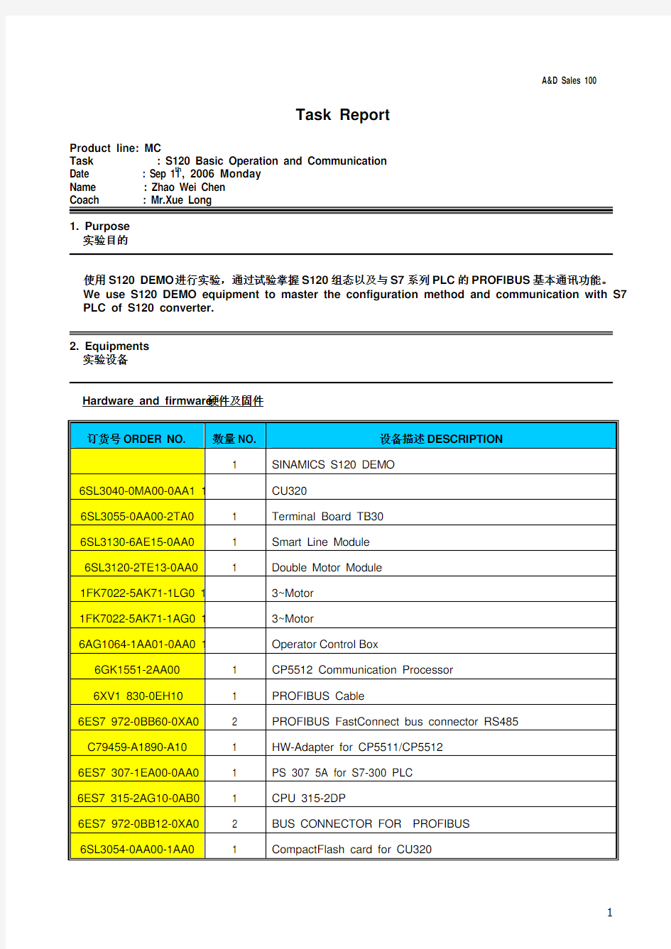
Task : S120 Basic Operation and Communication
Date : Sep 11th, 2006 Monday
Name : Zhao Wei Chen
Coach : Mr.Xue Long
1. Purpose
实验目的
Hardware and firmware硬件及固件
订货号ORDER NO. 数量NO. 设备描述DESCRIPTION
1 SINAMICS S120 DEMO
6SL3040-0MA00-0AA1 1 CU320
6SL3055-0AA00-2TA0 1 Terminal Board TB30
6SL3130-6AE15-0AA0 1 Smart Line Module
6SL3120-2TE13-0AA0 1 Double Motor Module
1FK7022-5AK71-1LG0 1 3~Motor
1FK7022-5AK71-1AG0 1 3~Motor
Box
Control
6AG1064-1AA01-0AA0 1 Operator
6GK1551-2AA00 1 CP5512 Communication Processor
6XV1 830-0EH10 1 PROFIBUS Cable
6ES7 972-0BB60-0XA0 2 PROFIBUS FastConnect bus connector RS485 C79459-A1890-A10 1 HW-Adapter for CP5511/CP5512
6ES7 307-1EA00-0AA0 1 PS 307 5A for S7-300 PLC
6ES7 315-2AG10-0AB0 1 CPU 315-2DP
6ES7 972-0BB12-0XA0 2 BUS CONNECTOR FOR PROFIBUS
6SL3054-0AA00-1AA0 1 CompactFlash card for CU320
Software and version软件及版本
订货号ORDER NO. 数量NO. 设备描述DESCRIPTION
6ES7 810-5CC08-0YA5 1 STEP 7 Professional Edition 2004
6SL3072-0AA0-0AG0 1 STARTER drive/commissioning software
3. Process and emphases
实验流程与重点难点
1、S120结构 Components of S120
本试验所用DEMO包含以下几部分:控制器、整流单元、变频单元和电机。
S120 DEMO includes: Controller, Line Module, Motor Module and Motors.
(1)控制器CU320 Controller CU320
控制器CU320提供以下接口:
CU320 includes the interfaces:
4四个Drive CLIQ插槽,可实现与其它Drive CLIQ设备的通信,例如电机模块、调节型电源模块(Active line)、传感器模块、终端模块。
4 Drive CLIQ, it can connect to other Drive CLIQ device, such as Motor Module, Active line module,
Sensor Module and Terminal Module.
1个PROFIBUS接口 1 PROFIBUS Interface
8点可参数化数字量输入(浮动式) 8 DIN
8点可参数化双向数字量输入/数字量输出(非浮动式),其中六点快速数字量输入
8 DIN/DOUT
1个RS232串行接口 1 RS232 Serial Interface
1个选件插槽,如TB30 1 Slot for selection board, such as TB30
3个测试插座和一个参考接地,用于调试 3 Testing Socket and 1 reference ground, for debugging CF卡: ROM卡,用于存储固件和参数设置。S120启动时,自动将组态信息和参数读入系统
注:一个CU320最多可以带4个矢量轴或6个饲服轴,但是不能混合使用,但是它们可以和V/F控制混合使用。
CF card: ROM, for storage firmware and parameters. When S120 starts, the system can reads configuration and parameters automatically from CF card.
Notice: The maximal numbers of one CU320 is 4 Vector axes or 6 Servo axes, but can’t mix use, it can mix with V/F Control.
(2)整流单元
Line Module
特点
分类
整流再生/反馈母线电压Drive-CLIQ 是否受电网波动影响BLM 二极管整流桥否不可调节,513V 是
SLM 二极管整流桥 IGBT 不可调节,513V 无是
配有升压变压器,增高
有否
ALM 二极管整流桥可控IGBT
的可调直流链路电压
(3)变频单元 Motor Module
分单轴和双轴模板 Signal and Dual axes Module
(4)选件 Addition Component
CBC10通信模板:CAN协议通信
CBC10 Communication Module: CAN Protocol
TB30: 扩展CU320的DI、DO、AI和AO,插在CU320的选件插槽内
TB30: Expend DI, DO, AI, AO of CU320, insert into CU320 slot
TM31: 输入输出端子扩展,卡在DIN导轨上
TM31: Expending Board
编码器模板:(注:电机与编码器模板通过扁平电缆连接,编码器模板与Motor module通过Drive CLIQ 连接)
Encoder Board: We connect Motor and Encoder with usual cable, and connect Encoder Board with Motor Module with Drive CLIQ.
模板类型编码器信号
SMC10 2极或多极旋转变压器
绝对值编码器,EnDat
SMC20
增量式编码器,sin/cos 1 Vpp
SMC30 TTL/HTL增量式编码器
2、S120组态 Configuration
首先连接PC和S120(CU320上的PROFIBUS口);然后对PC/PG Interface进行设置,设为CP5512(PROFIBUS)。
First, connect PC and S120 (the PROFIBUS Interface on CU320); Second, set CP5512 (PROFIBUS) mode in “Set PC/PG” window.
自动组态:Automatic Configuration
(1)建立S120项目,选择S120的PROFIBUS网络地址以及版本号,本试验中S120的DP地址为3,版本号为2.4x。其中,S120的PROFIBUS地址可以通过CP5512卡诊断出来,也可以通过CU320上的硬件拨码开关读出。
Build a new S120 project. Set the PROFIBUS Network address and Version of S120. We set DP address to 3 and version to 2.4x. We can confirm PROFIBUS address ether from CP5512 diagnostic or switch on CU320.
如果使用CP5512卡进行Test出现如下错误的话,请在Set PC/PG Interface->Properties->PG/PC is the only master on the bus进行选择。
If error like blow happens, go to Set PC/PG Interface->Properties, select PG/PC is the only master on the bus.
(2)在线,恢复出厂设置 On line, restore Factory Setting.
(3)自动组态 Automatic Configuration
选择开始自动组态,出现如下对话框,选择所控制的电机类型(伺服型或矢量型)
Press” Start automatic configuration”, pop-up a window, select type of motors (Servo or Vector)
由于自动组态方式只对Drive CLIQ方式的电机有效,而SEVRO_03没有Drive CLIQ,所以自动组态的SEVRO_03有错,需要离线后删除,重新手动组态SEVRO_03。
Because the automatic configuration method only affects Drive CLIQ Motor, but the SEVRO_03 in S120 DEMO hasn’t Drive CLIQ, SEVRO_03 is error, we have to delete it after offline and configure it manually.
(4)手动插入非Drive CLIQ电机
Insert non Drive CLIQ Motor
式
选择带编码器的速度反馈控制方
Selecting Speed (with encoder)
选择双轴电机模块,并Selecting Double motor 选择P0864使能信号,我们选择1,使其处于自动使能状态 Set P0864 = 1
nnection, because Connection X2 is used by Drive CLIQ motor, we select Connection X1 here.
选择其具体订货号
modules and its order number
选择连接关系,由于带有Drive CLIQ 的电机占用了Connection X2,因此我们在这里选择Connection X1。
Selecting co
在标准电机列表中选择电机类型以及具体的性能指标
Selecting Motor from Motor List
根据电机订货号选择是否带抱闸功能
Selecting with or without holding break according to the order number of motor
选择编码器类型
Selecting motor encoder
选择用于PROFIBUS通讯的PZD桢格式
Selecting PROFIBUS PZD frame
至此,我们就完成了添加非Drive CLIQ电机的工作
We finished insert standard motor
(5)点击在线,此时会出现离线和在线状态的不同之处,我们将上述在PC机中更改的信息下载到S120中
Press online, there will be a window that displays the difference between online and offline, and we download new information to S120.
(6)设置两电机的两个参数,P0210 = 345,P0864 = 1(右键单击电机导出Expert List),将等级修改为3,专家级。
Set 2 parameters, P0210 = 345, P0864 = 1, press right button of mouse and export the expert list,
modify the access level to 3, expert level.
Set the speed for drives to test them by using control panel in STARTER
手动组态 Manual Configuration
(1)新建S120项目,如前所述。先在线恢复出厂设置,再离线进行S120的配置(与自动组态不同,自动组态在在线的情况下)。
Build new S120 project, just as the steps blow. First resume the factory settings, then configure S120 device unit in offline mode (different with Automatic Configuration, we configure in online
mode in that situation).
(2)配置驱动单元 Configure drive unit
选择TB30选件板 Selecting TB30 optional board
选择整流模块是否有Drive CLIQ连接,S120 DEMO中的整流模块没有使用这种连接Selecting Line Module whether had a Drive CLIQ connection, we don’t use
选择使用编码器 Selecting use encoder
之后进入电机配置向导,具体步骤如前述所述,所不同的是这里配置两个电机,其中一个具有Drive CLIQ 连接,在选项上稍有不同,而另外一个标准电机则完全如上述过程所示。
注意,在进行第二个电机配置时,选择电机具体型号必须选择已经配好的第一台电机,否则配置会失效。Then we enter motor configuration guide, just as the steps above, some differences is that we configure 2 motors here and one of them has DRIVE CLIQ connection, the other one is the standard motor, completely the same with the above steps.
Notice, when configuring 2nd motor, we must select 1st motor that had configured, otherwise the configuration process will abate.
(3)设置P0210和P0864两个参数,然后在控制面板中对电机进行转速控制,如前所述
Set P0210 and P0864 parameters, then set the speed for drives to test them by using control panel in STARTER
(4)如果不能操作电机,要检查S120的拓扑结构,手动组态下PC机的结构很有可能与实际连接的结构不同,因此需要修改拓扑结构,或者修改PC机中的拓扑图,或者将S120 DEMO上的Drive CLIQ实际连线更改。
注意:手动组态下,两台电机要分别与Motor Module中的轴连接要对应,如果顺序颠倒,则不能够控制电机。
If we can’t control motor, we have to check the topology of S120, because the topology structure in PC maybe different with the actual topology, we have to modify the topology in PC or modify the actual line on S120 DEMO.
Notice: When configure manually, the 2 motors should corresponding to the 2 axes in motor module, otherwise we couldn’t control motors.
3、S120与S7-300之间的通讯 Communication of S7-300 with S120
实验内容如下:
试验内容
组态
功能块
周期性数据的通信
(PZD ) STEP7中PZD 地址有效区域分为四部分,每一部分都需要独立定其报文结构 上述PZD 的顺序由Object NO 决定
可以通过参数P978(0..15)修改顺序 TB30 Drive1 Drive2 CU320 SFC14/15 或MOVE 指令
非周期性通讯方式读取
驱动器参数
交换大量用户数据(最多240bytes ) 根据报文结构,利用功能块实现(与MM440不同,不能在STEP 中组态实现
PKW 的传输)
SFC58/59
(1)组态S7-300 Configuration S7-300
使用PROFIBUS 电缆连接S7-300与S120
Connect S7-300 with S120 through PROFIBUS cable
在STEP7中新建项目,插入S7-300站及相应模块
Build up a new project in STEP7, insert S7-300 and other related modules
将SINAMICS S120组态到DP 网络中 Insert SINAMICS S120 to DP network
注意设置好DP 网络的属性,其中S7-300为主站,S120为从站设备,并且站号分别为2和3。
Pay attention to DP property, S7-300 is master and S120 is slave, the PROFIBUS address are 2 and 3.
分别添加CU320、Drive_1、Drive_2和TB30的PZD 报文,其添加顺序可以从STARTER 中查到,注意各自PZD 报文的地址。
Insert PZD message for CU320, Drive_1, Drive_2 and TB30, its sequence can find in STARTER, look out of the address of PZD.
编译并下载组态 Compile and download the configuration
(2)组态S120 Configuration S120
如组态S120步骤所述,并且改变Drive_1和Drive_2的消息桢格式,如上图所示。
Change Drive_1 and Drive_2 message frame type on the basic of the configuration steps above and just as the picture above.
(3)STEP7编程 Program in STEP7
建DB1块,定义8字节长的PZD数据桢空间以及初始值
Build up DB1, define 8 bytes PZD message frame and its initialize value
在OB1中调用SFC14/SFC15,如下图所示,图中程序块用来控制Drive_2
Use SFC14/SFC15 in OB1, as the picture below, the program is used to control Drive_2
将DB1.DBW0从47E 修改为47F 来控制电机运行
Modify DB1.DBW0 from 47E to 47F to control motor
PZD 报文结构
PZD Frame
读/写
PZD 描述
PZD1 CTW1:控制字, 1WORD
PZD2
PZD3
N_SETP :速度设定值,2WORD Bit 31为符号位,速度通过P2000归一化
P1155
写
PZD4 CTW2:控制字, 1WORD PZD1 STW1:状态字, 1WORD
r2089[0] PZD2 PZD3 实际速度值
r63 读
PZD4
STW2:状态字, 1WORD
r2089[0]
4. What I have learned 心得与体会
1、一个CU320最多可以带4个矢量轴或6个饲服轴,但是不能混合使用,但是它们可以和V/F 控制混合使用。
1. the maximal numbers of one CU320 is 4 Vector axes or 6 Servo axes, butcan’t mix use, it can mix with V/F Control.
2、手动组态时,在进行第二个电机配置时,选择电机具体型号必须选择已经配好的第一台电机,否则配置
会失效。
2. when configuring 2nd motor, we must select 1st motor that had configured, otherwise the
configuration process will abate.
5. Application range
应用范围
SIMATIC S7-300 User Manual
PT4 S120教材
SINAMICS S120 Cabinet Modules User Manual
SINAMICS S120快速入门 V1.3