Development of3kW at325MHz solid-state RF power ampli?er using
four power ampli?er modules
B.V.Ramarao a,n,S.Sonal a,J.K.Mishra a,M.Pande a,P.Singh a,G.Kumar b,J.Mukherjee b
a Ion Accelerator Development Division,Bhabha Atomic Research Center,Mumbai400085,India
b Indian Institute of Technology,Powai,Mumbai400076,India
a r t i c l e i n f o
Article history:
Received21December2012
Received in revised form
12August2013
Accepted24September2013
Available online1October2013
Keywords:
Power ampli?er
Combiner
Solid-state
a b s t r a c t
A high power solid-state RF power ampli?er of3kW at325MHz has been developed using only four RF
power ampli?er modules of850W power output each.The design and characterization of RF power
modules have been presented.A four way Wilkinson power combiner adds the output of four power
ampli?er modules with a total transmission loss of less than6%.The combined power ampli?er has a
power gain of20.2dB at1-dB compression point,and the corresponding output power is2.8kW at
325MHz.The drain ef?ciency of the power ampli?er is65.3%at3kW.All the harmonics of this ampli?er
are belowà40dBc.The ampli?er has better characteristics like fewer numbers of active devices per kilo
watt,high ef?ciency,high gain,and ruggedness etc for RF accelerator applications.
&2013Elsevier B.V.All rights reserved.
1.Introduction
Due to limited power output of the solid-state RF devices like
bipolar junction transistors and MOSFETs,for several years the
solid-state RF power ampli?ers(SSRFPA)have been used as driver
ampli?ers of the high power ampli?ers for RF accelerators[1,2].
With the advancement of Laterally Diffused MOS(LDMOS)tech-
nology,the power output of solid-state RF devices has been
pushed up to few hundreds of watts.Initially the semiconductor
device manufacturers,Polyfet and Semi-lab have developed the
devices with output power of350W over a frequency band of
1–400MHz[3,4].Recently the Freescale semiconductors has
developed an LDMOS transistor which gives power output up to
1kW over a frequency band of10–500MHz[5].The Philips(NXP)
has also developed devices which can give output power of up to
1kW.These devices are suitable for RF ampli?er development for
modern accelerators.
The solid-state RF power ampli?ers have many advantages over
the vacuum tubes and klystrons.SSRFPAs have advantages like
simple start-up procedure(no warm-up time for?lament),long
life time(MTBF of over100years),and requires low voltage power
supplies and low power circulators.Due to its modularity,SSRFPA
delivers the part of the total output power to RF accelerator even
though few of its modules have blown off.The modularity nature
of the SSRFPA also derives the advantage of recon?guring the
speci?c number of modules for desired power output.It does not
require several power supplies like?lament,grids,and anode as in
vacuum tube ampli?ers.
Due to the advancement of cryogenic technology and use of
super conducting RF resonating cavities(SCRF)for modern RF
accelerators,the RF power requirement has come down drastically
for the same accelerating potentials[6].The few tens of kilo watts of
RF power is only required for an SCRF accelerator compared to room
temperature accelerators.The Solid-state RF power ampli?ers are
suitable for these super conducting accelerator applications.The cost
of such ampli?ers is comparable to that of vacuum tube ampli?ers
[7].In view of these merits,several labs over the world have started
research on the development of solid-state RF power ampli?ers.
SOLIEL,France has developed a35kW and190kW SSRFPAs at
352MHz for booster and storage ring accelerators of synchrotron
respectively[8].The solid-state ampli?er modules in this develop-
ment have power output of330W each.RRCAT,India has developed
a50kW SSRFPA at505MHz for Indus-2RF accelerator[9].The RF
power output of the modules in this is250W.The same lab has
developed another power ampli?er at20kW at505MHz using32
modules of400W output each[10].Desy,Germany has developed a
2.5kW SSPA at500MHz[11].A4kW at500MHz compact SSPA
development using18modules is reported in Ref.[12].In a similar
way BARC,India has also started research on the development of
SSRFPA in the year2005.Subsequently,it has developed a couple of
SSRFPAs for accelerators[13,14].Experience of earlier developments
is used in the present design.This development is mainly focused to
drive the prototype single spoke RF(SSRF)resonators of200MeV
accelerator of the phase II of ADS project,BARC.Finally a7kW RF
ampli?ers drives the SSRF cavities.Current development justi?es
this application.The paper presents the design and experimental
Contents lists available at ScienceDirect
journal homepage:https://www.doczj.com/doc/482216689.html,/locate/nima
Nuclear Instruments and Methods in
Physics Research A
0168-9002/$-see front matter&2013Elsevier B.V.All rights reserved.
https://www.doczj.com/doc/482216689.html,/10.1016/j.nima.2013.09.053
n Corresponding author.Tel.:t912225596117.
E-mail addresses:bvram@https://www.doczj.com/doc/482216689.html,.in,08407702@iitb.ac.in(B.V.Ramarao).
Nuclear Instruments and Methods in Physics Research A735(2014)283–290
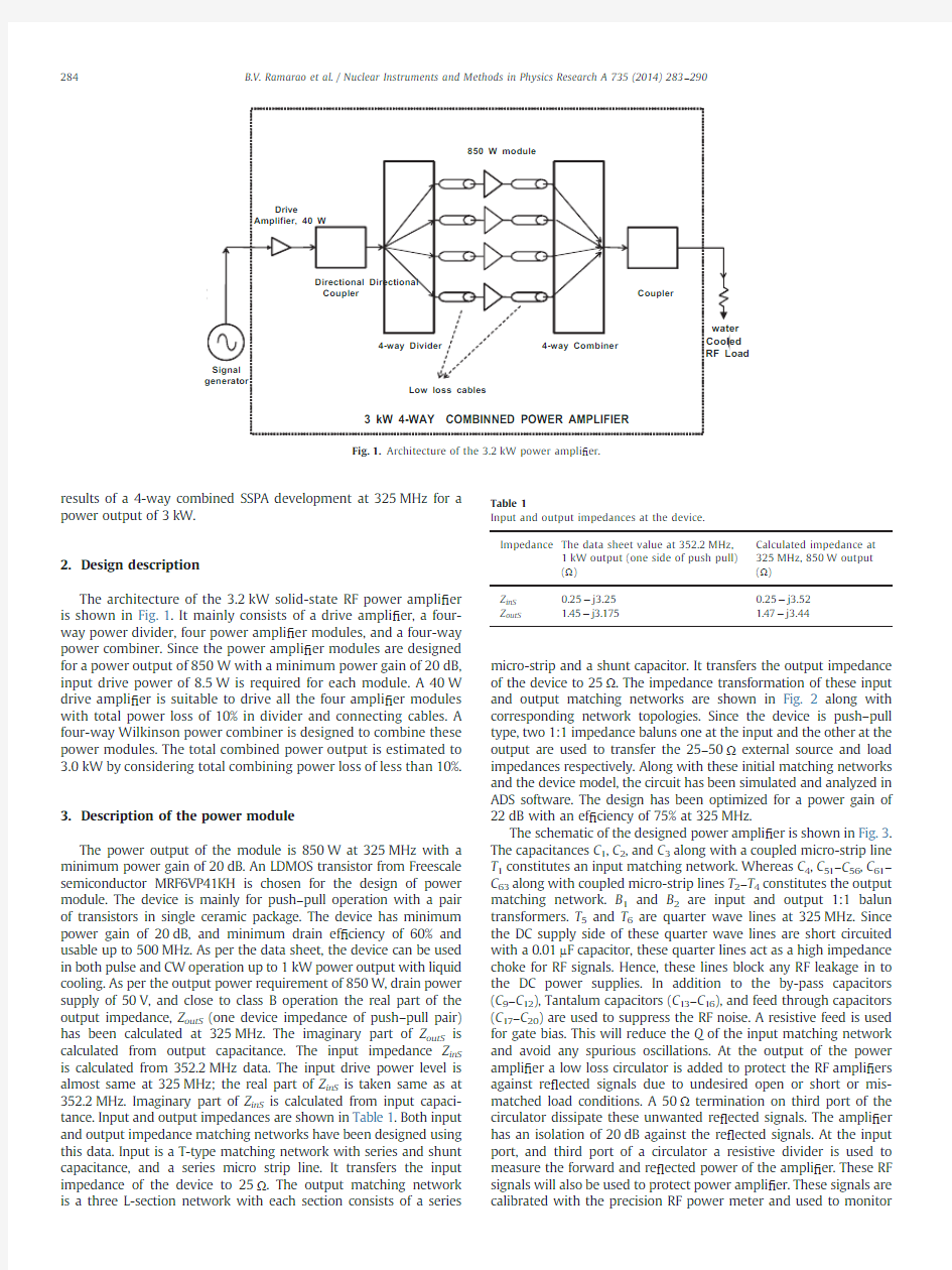
results of a 4-way combined SSPA development at 325MHz for a power output of 3kW.
2.Design description
The architecture of the 3.2kW solid-state RF power ampli ?er is shown in Fig.1.It mainly consists of a drive ampli ?er,a four-way power divider,four power ampli ?er modules,and a four-way power combiner.Since the power ampli ?er modules are designed for a power output of 850W with a minimum power gain of 20dB,input drive power of 8.5W is required for each module.A 40W drive ampli ?er is suitable to drive all the four ampli ?er modules with total power loss of 10%in divider and connecting cables.A four-way Wilkinson power combiner is designed to combine these power modules.The total combined power output is estimated to 3.0kW by considering total combining power loss of less than 10%.
3.Description of the power module
The power output of the module is 850W at 325MHz with a minimum power gain of 20dB.An LDMOS transistor from Freescale semiconductor MRF6VP41KH is chosen for the design of power module.The device is mainly for push –pull operation with a pair of transistors in single ceramic package.The device has minimum power gain of 20dB,and minimum drain ef ?ciency of 60%and usable up to 500MHz.As per the data sheet,the device can be used in both pulse and CW operation up to 1kW power output with liquid cooling.As per the output power requirement of 850W,drain power supply of 50V,and close to class B operation the real part of the output impedance,Z outS (one device impedance of push –pull pair)has been calculated at 325MHz.The imaginary part of Z outS is calculated from output capacitance.The input impedance Z inS is calculated from 352.2MHz data.The input drive power level is almost same at 325MHz;the real part of Z inS is taken same as at 352.2MHz.Imaginary part of Z inS is calculated from input capaci-tance.Input and output impedances are shown in Table 1.Both input and output impedance matching networks have been designed using this data.Input is a T-type matching network with series and shunt capacitance,and a series micro strip line.It transfers the input impedance of the device to 25Ω.The output matching network is a three L-section network with each section consists of a series
micro-strip and a shunt capacitor.It transfers the output impedance of the device to 25Ω.The impedance transformation of these input and output matching networks are shown in Fig.2along with corresponding network topologies.Since the device is push –pull type,two 1:1impedance baluns one at the input and the other at the output are used to transfer the 25–50Ωexternal source and load impedances respectively.Along with these initial matching networks and the device model,the circuit has been simulated and analyzed in ADS software.The design has been optimized for a power gain of 22dB with an ef ?ciency of 75%at 325MHz.
The schematic of the designed power ampli ?er is shown in Fig.3.The capacitances C 1,C 2,and C 3along with a coupled micro-strip line T 1constitutes an input matching network.Whereas C 4,C 51–C 56,C 61–C 63along with coupled micro-strip lines T 2–T 4constitutes the output matching network.B 1and B 2are input and output 1:1balun transformers.T 5and T 6are quarter wave lines at 325MHz.Since the DC supply side of these quarter wave lines are short circuited with a 0.01m F capacitor,these quarter lines act as a high impedance choke for RF signals.Hence,these lines block any RF leakage in to the DC power supplies.In addition to the by-pass capacitors (C 9–C 12),Tantalum capacitors (C 13–C 16),and feed through capacitors (C 17–C 20)are used to suppress the RF noise.A resistive feed is used for gate bias.This will reduce the Q of the input matching network and avoid any spurious oscillations.At the output of the power ampli ?er a low loss circulator is added to protect the RF ampli ?ers against re ?ected signals due to undesired open or short or mis-matched load conditions.A 50Ωtermination on third port of the circulator dissipate these unwanted re ?ected signals.The ampli ?er has an isolation of 20dB against the re ?ected signals.At the input port,and third port of a circulator a resistive divider is used to measure the forward and re ?ected power of the ampli ?er.These RF signals will also be used to protect power ampli ?er.These signals are calibrated with the precision RF power meter and used to monitor
850 W module
Drive
Amplifier, 40 W
Directional Directional
Coupler Coupler
4-way Combiner
4-way Divider
water Cooled RF Load
Low loss cables
Signal
generator
3 kW 4-WAY COMBINNED POWER AMPLIFIER
Fig.1.Architecture of the 3.2kW power ampli ?er.
Table 1
Input and output impedances at the device.Impedance The data sheet value at 352.2MHz,
1kW output (one side of push pull)(Ω)Calculated impedance at 325MHz,850W output (Ω)Z inS 0.25àj3.250.25àj3.52Z outS
1.45àj3.175
1.47àj3.44
B.V.Ramarao et al./Nuclear Instruments and Methods in Physics Research A 735(2014)283–290
284
the incident and re ?ected power.No additional directional coupler is needed at the output of the power ampli ?er to measure the output power.
The design has been implemented on a low loss microwave substrate,Rogers Corporation make Duroid 5880.The fabricated power ampli ?er module is shown in Fig.4.The input balun B 1is made from a semi-rigid coaxial cable of UT-141-TP and where as output balun B 2is made from a semi rigid coaxial cable of UT-250C.The input and output matching capacitors (C 1,C 3,C 51–C 56,and C 61–C 63)are low loss multilayer ceramic chip capacitors (ATC100B).Since in one of the output matching L-section current is high,a high power mica capacitor from MTM is used for C 4.The three port circulator is Volvo,German made and has insertion loss of 0.2dB at 325MHz.It has input return loss of 23dB and isolation of 25
dB.
Fig.2.Impedance transformation along with matching network
topologies.
B 2
DD
Fig.3.Schematic of the ampli ?er module.
Fig.4.Photograph of the fabricated power module.
B.V.Ramarao et al./Nuclear Instruments and Methods in Physics Research A 735(2014)283–290285
The power handling capacity of this drop in circulator is 1kW at 325MHz.An N-connector at the input and a 7/16DIN connector at the output are used for the power module.
In order to improve the thermal conductivity between the devices and water cooled Cu channel,both mosfet and dummy load of circulator are directly soldered to the Cu heat sink.The PCB is attached to the sink using heat sink compound.The ?ow rate of
6–8lpm is used to cool the module.Both the sides of the Cu heat sink are used to mount the power ampli ?ers.A total of two power ampli ?er modules,one on the top surface and the other on bottom surface are mounted on a common heat sink plate.A total two blocks are used to mount the four power ampli ?er modules.The thermal circuit of the power ampli ?ers on a single block is shown in Fig.5.The description of each parameter of the circuit is given in Table 2.
The measurement setup of the power ampli ?er module is shown in Fig.6.It consists of a signal generator,drive ampli ?er,two power meters along with their power sensors,two directional couplers (CP 1and CP 2),DC power supply,vector network analyzer (VNA),spectrum analyzer (SPA),and a test load.Signal generator is SMB type of Rhode &Schwartz (R&S)make with frequency range from 9kHz to 1GHz,and power level of 13dBm.Drive ampli ?er is of mini-circuit make and model no is ZHL-100.This is a broad band ampli ?er with power gain of 48dB,and gain ?atness of 70.5dB over a frequency range of 200–500MHz.Its harmonics and spurious is o à30dBc.Input directional coupler (CP 1)is of Bird communica-tions make,ACM500type whereas the output directional coupler (CP 2)is in-house designed.These devices have coupling coef ?cient of 63dB and 47dB respectively,and directivity of 425dB.The broad band RF signal sampler from Bird communications at load end is used to measure the harmonics in the output signal.The power meters are of R&S make,NRT model along with their power sensors of model numbers NRT-Z44,and NAP-Z6.The power sensor NRT-Z44is a low power type and where as NAP-Z6is a high power sensor.These sensors have an accuracy of 5%of the display over a frequency range of 200MHz to 1GHz.VNA and SPA are of R&S make with correspondingly model numbers of ZVT and FSH.Test load is a Bird communication make and it is rated for 1kW over a frequency range of DC-1GHz with VSWR o 1.1.A switch mode type DC power supply of 50V,40A from Digitronics,Pune is used for drain bias.Also measured the RF power using calorie meter method using water cooled RF load.
A four port VNA has been used to measure the gain and phase characteristics of the power ampli ?er.Its power and frequency sweep options are used to characterize the power ampli ?er.Power meter readings are also used to calculate the drain ef ?ciency and
Device 1Device 2P D1
P D2T j1R ?j1
R ?j2R solder2
R solder1
R sink1C sink2
C sink2
T water
R sink2T j2
T c1
T cu1
T c2
T cu2Fig.5.Thermal circuit of the ampli ?er module.
Table 2
Description of the thermal circuit parameters.
Parameter Description (‘x ’is 1for device1and 2for device2).T jx Junction temperature of device ‘x ’.P Dx Power dissipated in device ‘x ’.
R ?jx Junction to case thermal resistance of device ‘x ’.T cx
Case temperature of device ‘x ’.
R solderx Thermal resistance of the solder joint of device ‘x ’.T cux Copper plate surface temperature on ‘device x ’side.
R sinkx Thermal resistance of device ‘x ’side of the water cooled Cu heat sink.
C sinkx Thermal capacity of device ‘x ’side of the water cooled Cu heat sink.T w
Common outlet water temperature.
DC 50 V, 40A
Water
Power Power Meter
Sig. Generator
NRT
NRT
Meter
Dir. Coup ACM-500CP 2
CP 1
Drive Amplifier
Water Dir. Power sensor
NAP-Z6
NRT-Z44
I
R
T
ZHL-100
Dir. Power sensor D
Cooled RF Load
VNA
Spectrum Analyzer
I L k nt e r ock Circuit
ZVT
FSH
DUT
Fig.6.Measurement setup of the ampli ?er.
B.V.Ramarao et al./Nuclear Instruments and Methods in Physics Research A 735(2014)283–290
286
power added ef ?ciency in addition to absolute power measure-ment.Spectrum analyzer is used to measure the harmonics and spurious output with reference to center frequency.
Output signals from the directional couplers CP 1and CP 2(I ,R -forward and re ?ected coupled signal of CP 1,T -forward coupled signal of CP 2)are used to measure the input match,power gain,and phase response.The VNA is used in receiver mode at three of its ports.While characterizing the power ampli ?er,the drive signal (D )is taken from fourth port of VNA in order to synchronize received signals.The signal ratio R to I is used to measure the input match,S11of the ampli ?er.The signal ratio,T to I is used to measure the gain and phase response.The signal from the sampler
is used to measure the harmonics and spurious in SPA.Measured RF performance parameters like power gain,drain ef ?ciency,PAE,and VSWR have been shown in Fig.7.At 1-dB compression point,the power ampli ?er has power gain of 21.2dB and drain ef ?ciency of 69.8%.The corresponding power output is 800W.Since the ampli ?er is tuned at its maximum power output,the input VSWR at 1-dB compression point is 1.28.The PAE at 800W is 69.4%.The measured 2nd and 3rd harmonic is shown in Fig.8.The 2nd harmonic component is well below 40dBc and whereas 3rd harmonic is below 58dBc.The temperature of the output match-ing network capacitors have been measured using infrared ther-mometer.All capacitors have surface temperature less than 1331C.Surface temperature of output matching capacitors are shown in Table 3.
4.Characterization of power modules
The four power ampli ?er modules numbered from A1to A4on two Cu blocks have been characterized in a standard measurement setup shown in Fig.6of Section 3.The measured power gain of the power ampli ?ers at various output power level is shown in Fig.9.The ampli ?er module A3has maximum power gain of 22dB at 1dB gain compression point,and the corresponding power output is 800W.The ampli ?er module A2has minimum power gain of 21.2dB at 1dB gain compression output of 800W.The maximum gain deviation is 0.8dB among the power ampli ?er modules.The measured phase shift versus output power at 325MHz is shown in Fig.10.The ampli ?er modules have maximum phase deviation of 101among the
modules.
Fig.7.Measured performance parameters of the power ampli ?er at 325
MHz.
Fig.8.Measured harmonics of the power ampli ?er.
Table 3
Temperature of output matching capacitors at 800W.Capacitor Temperature (1C)C 4
133C 51and C 5686C 52–C 5564C 61
72C 62,C 63
70
Fig.9.Measured power gain of the
modules.
Fig.10.Measured phase of the modules.
B.V.Ramarao et al./Nuclear Instruments and Methods in Physics Research A 735(2014)283–290287
5.Description of the power combiner
The geometry of the power combiner is shown in Fig.11.It is a basic Wilkinson type 4-way power combiner with radial input signal launches [15].It consists of an inner cylinder which has been split into four equal splines,a thin metal disc which joins the splines,an outer cylinder,a taper section,and a Te ?on disc to support the splines and also to maintain the spacing between the splines.The main coaxial line is air dielectric and the length of the splines is quarter wave length,λo /4at the operating frequency of 325MHz,which is calculated to 220mm.The characteristic impedance of the splines Z depends on the circumferential spacing between the two splines and the outer conductor.The initial value
of the Z is given by Z ?Z o sqrt eN T
e1T
where Z o is impedance of the external source or load
N is the number of input ports,which are 4in this 4-way power combiner.The Z is calculated out to 100Ω.The characteristic impedance of the un-split coaxial line is Z c ?Z o /sqrt(N ),which is 25Ω.Since it is a high power combiner,the spacing between the two conductors is chosen to avoid the break down between the conductors.The spacing between the conductors,s is chosen as 7mm with safety factor of 410for 5kW CW operation.The inner radius (r )and outer radius (R )are calculated using Z c ?60ln eR =r T
e2T
where outer radius,R ?r ts .
Electromagnetic (EM)simulation is carried on the geometry with the above calculated geometrical parameters.The cutting angle between the strips,?is chosen as variable parameters.RF performance parameters of the power combiner have been stu-died against the variation of this parameters.
The change in the output match,input match,insertion loss,and isolation with respect to ?is shown in Fig.12.At the cutting angle of 601output match |S44|is better than 50dB at 325MHz but the isolation is poor and it is 4à25dB.Also input match is only at à13dB.So at the cutting angle of 401both isolation and input match are better,and output match is also better than 35dB.The device has been fabricated in copper material to have minimum insertion losses.To avoid the oxidation of its surfaces,inner parts are Gold plated with 1μm thickness and outside
powder
Fig.11.Geometry of the four way power
combiner.
Fig.12.Effects of cut angle on S parameters of the
combiner.
Fig.13.Characterization of combiner using
VNA.
Fig.14.Measured isolation among the input ports without balancing resistors.
B.V.Ramarao et al./Nuclear Instruments and Methods in Physics Research A 735(2014)283–290
288
coated.Input power level is at $1kW,a suitable RF connector for this is 7/16mm DIN connector is used for input signals.Whereas output or combined power is close to 4kW at 325MHz,a suitable RF connector for this power level is EIA:1–5/8”has been used for output power.The designed power combiner has been characterized on a 4-port VNA ZVT from Rhode and Schwartz.The measurement setup of the power combiner is shown in Fig.13.The combiner has 30MHz bandwidth over the |S44|o à20dB.The measured output port match and isolation parameters are shown in Fig.14.Without internal loads the measured isolation parameters are in close
agreement with the simulated parameters (o 0.2).The measured transmission coef ?cients are shown in Fig.15.The maximum insertion loss is o à0.5dB.The amplitude imbalance of the ports is o 70.25dB at 325MHz.The measured maximum phase imbal-ance is o 21at 325MHz.The comparison between measured and simulated parameters has been shown in Table 4.Two combiners are connected back to back with the low loss cables to measure the insertion loss for equal phase and level signals.The combiner has 1.85%loss in this case.
https://www.doczj.com/doc/482216689.html,bined power ampli ?er
The test setup of integrated power ampli ?er using a drive ampli ?er,a power divider,four power ampli ?er modules,and a power combiner is shown in Fig.16.The input and output directional power sensors are used to monitor the input power of the divider and output power of the combined ampli ?er.Input power is measured using NRT-Z44power sensor along with NRT display unit.Output power is measured using 1–5/8directional coupler.An air cooled 5kW,50Ωload is used to dissipate the output power.It has also been measured with water cooled RF load (Bird make 8755).The measured power gain,and DC to RF conversion ef ?ciency is shown in Fig.17.The 1-dB gain compression point is at the power output of 2.8kW,and the corresponding power gain is 20.2dB.At saturation of 3kW,the power ampli ?er has power gain of 19.9dB at 325MHz.
The DC power to RF power conversion ef ?ciency,ηis shown in Fig.17.The ηis low at 30%at lower output power levels o 100W.The ηincreases with power output and it is maximum of 66%at 3kW.The power ampli ?er draws a maximum total current of 90A from a 50V DC power supply at 3kW output power.Total power gain from signal generator to 50Ωload is 69.6dB.There is only 2dB decrease in the power gain at 3kW from the maximum
gain.
Fig.15.Measured transmission loss.
Table 4
Comparison of simulated and measured RF parameters at 325MHz.RF parameter
Simulation
Measurement Output match (dB)
à40
à33Isolation among input ports (dB)o à22with balancing loads –
à12without loads
à12.6without loads Input port match (dB)à18with balancing loads –
à2.8dB without loads à2.3without loads Insertion loss,|Spq |(dB)
à6.02
à6.07
0.25
Fig.16.Test setup of the 3.2kW power ampli ?er.
B.V.Ramarao et al./Nuclear Instruments and Methods in Physics Research A 735(2014)283–290289
7.Conclusions
The developed 3kW solid-state power ampli ?er has several advantages over the earlier developments.These are mainly fewer number of semiconductor devices per each kilo watt of RF power output,and cost is also less compared to the SSRFPA with more
number of modules of lower output power.A comparison is made between this development and earlier developments in Table 5.
Acknowledgment
The authors are very thankful to the Director,Physics group for his continued support for this active research.They are also thankful to the mechanical staff and other support staff for their support in testing of the power combiner.References
[1]T.Ruan,et al.,EPAC98,Mosfet RF power ampli ?er for accelerator applications,
in:Proc.of EPAC98,Stockholm,1998,p.1811.
[2]Zhao Fengli,1kW S-band solid-state ampli ?er for BEPC linac microwave
driver system,in:Proc.of APAC,Beijing,Stockholm,2001.[3]?https://www.doczj.com/doc/482216689.html,/pdf/rf/DMD1029.pdf ?.[4]?https://www.doczj.com/doc/482216689.html,/dsheet/LR301.pdf ?.
[5]?https://www.doczj.com/doc/482216689.html,/?les/rf_if/doc/white_paper/50VRFLDMOSWP.pdf ?.
[6]R.L.Shef ?eld,Superconducting technologies for the advanced accelerator
applications program,in:Proc.of the 10th Work Shop on Super Conductivity,Tsukuba,2001,p.318.
[7]M.Gasper,Solid-state RF PA:practicality,cost,potentials,feasibility,trend and
outlook,in:Proc.of the 5th CW and High Average Power RF Work Shop,CERN,Geneva,Switzerland,2008.
[8]P.Marchand,et.al.,High power (35kW and 190kW)352MHz solid-state
ampli ?er for the SOLIEL synchrotran,in:Proc.of PAC,Tennessee,2005,p.811.[9]A.Jain,et al Design and characterization of 50kW solid-state RF ampli ?er
source,International Journal of Microwave and Wireless Technologies,4(2012)595–603.
[10]A.Jain,et al.,Nucl.Instrum.Meth.Phys.Res.A 676(2012)74.
[11]C.Piel,et al.,Development of solid state RF ampli ?er in the kw regime for
application with low beta super conducting RF cavities,in:Proc.of PAC-05,Tennesse,p.1.
[12]M.Gasper,Nucl.Instrum.Meth.Phys.Res.A 637(2011)18.
[13]V.R.Bala,J.K.Mishra,M.Pande,V.K.Handu,G.Kumar J.Mukherjee,Analysis and
design of high power solid-state module at 350MHz for RF accelerator,in:Proc.of the Indian Particle Accelerator Conference,New Delhi,India,2011,p.232.
[14]B.V.R.Rao,M.K.V.Rao,V.K.Handu,Development of UHF Solid-State Driver
@350MHz for a Klystron Based 1MW RF Power Source in:Proc.of InPac,2005,p.390.
[15]E.Wilkinson,IRE Transactions on Microwave Theory and Techniques (1960)116
.
Fig.17.Measured power gain and drain ef ?ciency of the power ampli ?er.
Table 5
Comparison of this development with the earlier developments.Parameter
Ref.[8]a Ref.[10]Ref.[12]This development Module output (W)330400400850No.of devices (kW) 3.3 2.5 2.5 1.2Ef ?ciency (%)65656569.8Gain (dB)
13
20
20
21
n
Recently the same authors have developed 700W ampli ?ers but data is not available.
B.V.Ramarao et al./Nuclear Instruments and Methods in Physics Research A 735(2014)283–290
290
Unit 3 Look at Me (第二课时教学设计) 段利芸 一、教材依据: PEP版小学英语三年级上册第三单元Part A Let’s learn / do. 二、设计思路: 《国家英语课程标准》明确指出:采用活动途径,倡导体验参与,通过感知、体验、实践、参与等方式,实现任务目标,感受成功,以积极地学习态度,促进语言实际运用能力的提高。所以本节课我利用PPT 及听听、说说、看看,读读、猜猜、、唱唱等活动促使学生轻松愉快地完成本节任务。 三、教学目标 1. 能听说、认读eye,face,ear,nose,mouth这些关于身体部位的单词,并能用英语介绍自己身体的这几个部分。 2、能听懂指示语Touch your…并能按指令做动作。 3、激发英语学习兴趣,让学生对英语乐学、想学。 四.教学重点: 1、对句型“close your eyes/open your mouth/touch your nose/ear/face的理解和掌握。 2、关于头部的单词eye,face,ear,nose,mouth的学习。五.教学难点: eye,face两个单词的元音因素容易发音不到位,教师可鼓励
学生张大口型,相互检查。mouth一词的尾音发音较难,教师可适当提醒学生,注意口型。 六、教学准备 (一)教师准备 1. eye,face,ear,nose,mouth的单词卡片和图片。 2. Let's do部分中的有关动作的图片。 3. 教材配套的录音带。 4. Chen Jie,Mike,Wu Yifan,Sarah,Zip,Zoom的头饰。 5. 头部及五官课件。 七.教学过程 Step 1. Warm-up/Revision 1、师生共同演唱、复习所学歌曲《Hello》。 2、教师回顾性、概述性讲解,复习上节课所学的“How are you?”“I’m fine,thank you.”等句型和表达法。 3、按小组让学生戴上Chen Jie,Mike,Wu Yifan,Sarah,Zip,Zoom的头饰,练习本课A部分Let's talk 的对话。 Step 2.Presentation 1、学习有关身体部位的词 (1)再次出现第一课时教师曾用过的木偶,用木偶表演的方式来进行自我介绍并介绍朋友的姓名。教师引入小木偶进行介绍:This is my nose. / This is my eye等,由此引出本课单词的教学eye,face,ear,nose,mouth,让学生初步了解单
Pep三年级英语Unit 3 Look at me!第二次课 一、教学目标 1.在实际情境中熟练运用Good morning / afternoon! This is…… Nice to meet you. / Nice to meet you. / Nice to meet you, too. Let’s go to school. 2.能听说、认读关于身体部位的单词,并能用英语介绍自己身体的部位。 3.能将单词face, ear, eye, nose, mouth, arm, hand, head, body, leg, foot, 运用到介绍的句型:This is…… 4.能认知clap, touch, wave, shake, stamp五个单词,并按照指示做相应的动作。 二、重难点 1.上午和下午的问候语:Good evening与good night的区别。 2.熟练掌握介绍的句型:This is…… 3.说说做做的意思及动作指示。 4.熟练认读并按正确笔划书写Ee Ff Gg Hh Ii,能认知以其为字母开头的单词。 5.介绍自己的身体部位。 三、教学过程 Step 1.warming up 1.复习趣味歌曲熟悉单词。 我的身体body真奇妙,head头善思考。 鼻子nose有点儿翘,眼睛eye视力好。 Hand,hand手真巧,foot脚能跑又能跳。每天运动身体好。 2.小组活动:Listen and point 教师让学生按小组练习head, eye, face , ear, nose, mouth 。方法是,小组的每一个组员分别说一个单词,其他同学指出相应的部位。 3.全体活动:Listen and draw 学生按教师的指令画图,如教师说:Draw a mouth. (画一只熊的嘴巴)学生则画出一张嘴,用此方法重复操练nose, eye, face , ear, head ,最后画出完整的一幅画。(可以让一、两个学生到黑板上画,起引导作用) 4.教师带读,学生跟读,边说边做Let’s do(P25, P28)部分中的活动。 5.游戏:比一比 将学生分为两大组,每组各派一个选手,教师说句子,选手快速跑到讲台找到所听句子的图片,并举起图片大声读出,这样即为胜利,为本组加一分。之后,在换另一名选手进行。失败的一组做动作,胜利的一组说动作。
Unit 3 Look at me ! Part A Let’s talk Let’s play 教学内容: Part A Let’s talk Let’s play 教学目标: 1. 能在语境中理解并运用句型How are you ? I’m fine , thank you .有礼貌的询问他人的近况并进行回答; 2. 能运用Let’s go to school . 建议他人一起做某事; 3. 进一步培养学生学习英语的兴趣和敢于开口、勇于表达的习惯。 教学重点、难点: 重点:掌握关于询问他人近况的问法及回答;建议做某事的表达及回答。 难点:在合适的语境中运用问候语及回答;字母i的发音,字母组合th的发音。 教具: Chen Jie、Mike头饰;课件;词条及图片。 教学设计: Step1:Warm-up and Revision 1.Let Ss do “Unit 2 B let’s do” 2.Greetings 3.Free talk T: Hello/Hi/Good afternoon. What’s your name ? Nice to meet you . 设计意图:选择Let’s do进行热身,是为下文引出go to school做铺垫,在Free talk中对已学问候语进行复习。 Step2: Presentation and Practice T: Look ! What’s the time ? We say good morning . Let Ss imitate . T: In the morning , Chen Jie carries the bag , so where is Chen Jie going ? T: Go to school .
小学英语PEP人教版教材三年级上册Unit 3 Look at me! 教学内容:Let’s talk Let’s play letters and sounds 教学目标: 1、知识目标:(1)能听懂、会说How are you?及回答。 (2)能了解、会说 Let's go to school. (3)能掌握e f g h i五个字母在单词中的发音。 2、能力目标:能运用句型进行交际。 3、情感目标:培养学生用英语问候他人的习惯。 教学重点:句型How are you?及回答。 教学难点:Let's go to school. 教学准备:头饰录音机词卡 教学过程: Step 1 Warm-up 教师带上Mike的头饰,走进教室,师生问候。 T: Good morning, boys and girls. S: Good morning ,Mike. T:Nice to meet you. S: Nice to meet you, too.出示Chen Jie 的头饰。 T: This is Chen Jie. S: Hi, Chen Jie. C: Nice to meet you. S: Nice to meet you, too. Step 2 Presentation (1)接着教师用Mike和Chen Jie 的头饰,以对话形式引出新授句型How are you?及回答。板书,带读。教师要注意How are you?是用于熟人之间有一段时间未见面,或是对方身体欠佳,或是较正式地向别人打招呼等场合。因此,要告诉学生,不必每次见面都问此话。每天见面时,只要说Hello!或Hi! 就可以了。(2)以开火车形式操练句型。一组为单位,做开火车的游戏。教师在每组选出一名“质量监督员”,监督每个同学提(绿色圃中小学教育网 https://www.doczj.com/doc/482216689.html, 原文地址 https://www.doczj.com/doc/482216689.html,/forum.php?mod=viewthread&tid=216868)问的完整性和正确率。(以计分形式评价学生)从第一个学生开始 Hi/Hello/Good morning, A . How are you? 第二个学生回答I’m fine./Fine, thank you. 并提问 How are you? 以此类推。(A代表学生姓名)。 (3)把全班分成两大组,一组是Mike组,一组是Chen Jie组。分角色表演对话。(以计分形式评价学生) (4)师背上书包,并出示school的图片问学生Let’s go to school. OK? S: OK! 板书教授。教师应从“Go to school” 导入到Let’s go to school.本句的发音较难,口型和发音不易到位,教师要适当提示,多带读操练。 (5)出示情景图,听录音,指,模仿跟读对话。 (6)Practice 学生带头饰表演对话,让学生进行评价。 (7)教授letters and sounds 用卡片出示单词带读,边指边听,在听音找词。归纳总结首字母的发音。
教学详案 教学内容:1 let’s learn 单词:ear, eye, face, mouth, nose 句子:look at me ,this is my _ear___ 2 let’s do Open your mouth Close your eyes Touch your face Touch your nose Touch your ear 霍琼琼: 以下是我的一点个人建议,你看看,行就用,不行就不用! 马 (1在你板书单词时,让学生用手一起跟着你书空,一起拼读单词字母 2单词的引出形势好的有两种:最后鼻子和头的引出不错,前面的眼睛,耳朵、嘴可多样化引出例如:猜谜语形式引出…… 3 head的出线可以放在eye nose ear mouth 之后,那样你在画出圆圈和头发后,学生一猜就是头,水到渠成。而不会出线胡萝卜西红柿一类的答案了! 4\、big small 单词学过吗,如果学过,可以让学生在介绍时加上,I have big eyes 或者small eyes
5 let’s do 放在第一个游戏之后,游戏是练习单词的,应紧跟单词句型之后,这样才衔接的顺利! 第二个游戏是练习LET‘s do 的,在学习完Let’s do 之后,在做第二个游戏!) 教学过程: Step 1 warming up T:boys and girls ,I’m your new english teacher,I hope we have a good time,I happy, you happy.OK?first of all,to do a let’s do.please turn to page 8.listen to the tape ,and do the action.the first time to listen ,the second time,read and do the action.Are you ready? T:very good. (let’s do open your pencil box. Close your book. Show me your pen. Carry your bag) Step 2 presentation 一、let’s learn 1 T:today we are going to learn the new lesson UNIT 3Look at me(板书课题),let’s read it ,look at me (师随读随做动作),read twice .OK, what mean ?who can answer? S:看看我 T::yes ,it means 看看我。OK, follow me ,look at me (做动作,读课题)
Unit 3 Look at Me 第二课时教学设计 一、教学目标 1. 能听说、认读head,eye,face,ear,nose,mouth这些关于身体部位的单词,并能用英语介绍自己身体的这几个部分。 2. 初步了解表示接触的指示用语,能听懂,并按指令做出相应的动作。 二、教学重点 关于头部的单词head,eye,face,ear,nose,mouth的学习。 三、教学难点 eye,face两个单词的元音因素容易发音不到位,教师可鼓励学生张大口型,相互检查。mouth一词的尾音发音较难,教师可适当提醒学生,注意口型。 四、教具准备 1. head,eye,face,ear,nose,mouth的图片。 2. Let's do部分中的有关动作的图片。 3. 用PowerPoint制作的头部及五官课件。 五、教学过程 1. 热身、复习(Warm-up/Revision) 师生共同复习所学歌曲《A B C song》。 2. 呈现新课(Presentation) (1)再次出现第一课时教师曾用过的图片,用图片来进行自我介绍并介绍朋友的姓名。教师以图片中的动物Zoom进行介绍:This is my nose. / This is my head. 等等,由此引出本课单词的教学head,eye,face,ear,nose,mouth,让学生先初步了解单词。 (2)教师指着自己说:Good morning. I'm Miss / Mr. ... Look at me. 指着自己的头说:This is my head. 用同样的方法依次介绍:eye,face,ear,nose,mouth,学生进一步学习单词。(注意:教师在介绍的同时指着自己身体各相应的部位。)(3)用PowerPoint制作的课件。教师点击鼠标后,眼、耳、鼻、口、脸和相应的英语单词逐一显示。 (4)教师再次借助动作和表情,比如,点点头、眨眨眼、摸摸鼻等,学习单词的听说。 注意:eye,face两个单词的元音因素容易发音不到位,教师可鼓励学生张大口型,相互检查。mouth一词的尾音发音较难,教师可适当提醒学生,注意口型。 (5)认读head,eye,face,ear,nose,mouth的单词卡片和图片。 (6)让学生听录音,跟读Let's learn部分的单词并要求学生指着自己的头部和相应的部位,力求做到“眼到、口到、心到、手到”。 3. 趣味操练(Practice)
The fifth period(第五课时) Part B Let’s learn & Let’s do ?教学内容与目标 课时教学内容课时教学目标 Let’s learn ·能够听、说、认读表示身体各部位名称的六个单词“head, hand, body, arm, leg, foot”·能够在图片、PPT和教师的帮助下理解Let’s learn板块中句子的含义 ·能够在情景中运用句型“This is the…”介绍身体各部位 Let’s do ·能够在图片、动作和音频的帮助下理解、跟读歌谣 ·能够根据指令做出相应的动作或根据动作说出相应的指令性用语 1能够听、说、认读表示身体各部位名称的六个单词“head, hand, body, arm, leg, foot”。 2 能够在情景中运用句型“This is the…”介绍身体各部位。 ?教学难点 能够区分单词“head”与“hand”的发音。 ?教学准备 1. 预习《状元大课堂》《创优作业100分》《状元作业本》中本课时的相关内容。 2. 教学课件、课文录音、视频、单词卡片、木偶等。 ?教学过程 Step 1: Warm-up & Revision & Lead-in 1. Greetings. 2. Revision. (1)Ask students to act out the dialogue of “Let’s talk” on page 27. (2)Play the video of “Let’s do” on page 25. (出示课件) Lead students to do the actions according to the video together. 3. Lead-in. Play the video of the song—Head and shoulders, knees and toes. (课件出示:教材P30 Let’s sing板块的歌曲视频) Step 2: Presentation 1. Teach the new words. (1)Teach the words “head, hand”. Show the picture of a cartoon character on the PPT. (出示课件)Dub the cartoon character. T: Boys and girls, do you still remember me? Ss: Yes. Teaching purpose 通过TPR活动,调动学生多种感官参与,在轻松愉快的氛围中复习旧知。通过歌曲引出新知,吸引学生注意力,创造良好的英语学习环境,为新课的学习做铺垫。 Teaching purpose 通过熟悉的卡通人物,自然导入新知。以多种形式教授新词,并且做到词不离句。通过自编chant,将单词和句型整合,让学生边说边做动作,加深学生对单词和句型的理解和记忆。 3
Unit 3 Look at me PartA Let’s learn&Let’s do 第二课时词句课 教师:何黎萍 教学目标:能够听说、认读eye, face, ear, nose, mouth,这些关于身体部位的单词,并能用英语介绍自己身体的部位。 教学重点:关于头部的单词eye, face , ear, nose, mouth的学习。 教学难点:eye, face 两个单词的元音因素容易发音不到位,教师可鼓励学生张大口型,相互检查。mouth 一词的尾音发音较难, 教师可适当提醒学生,注意口型。 课前准备:单词卡片和课件。 教学过程: 一、Warming up(3分钟) 1Greeting. 2Guess. 二、Presentation(20分钟) 1`T:Which seven holes? Show me. S:眼睛鼻子..... 2. 课件出示一个动画人物的脸猜猜这是谁?引入今天学的单词T:Look at me! This is my face.Show word card about face.Spell-write-read.同时引出句型:This is your face.
3 Look at me! This is my nose.Show word card about nose.Spell-write-read。同时引出句型:Touch your nose。 5 .T:What is this?教师指着不同的部位。 S : This is.... T:What is this?教师指着眼睛。学习eye .Show word card about eye.Spell-write-read.同时引出句型:close your eye. 5.Look at me! This is my mouth. Show word card about mouth.Spell-write-read. 同时引出句型:Open your mouth. 6. Look at me! This is my ear.同时揭开谜底他是大耳朵图图。Show word card about ear.Spell-write-read. 同时引出句型:Touch your ear. 7.Guess :Who is he?(出示课文主题图,边听边跟读,猜猜他是谁?) 三、Practice(15分钟) 1.语音训练活动:(1)找单词卡片游戏。(2)你大我小。 2.音义训练活动 (1) . What is missing? (2).I say you do ,I do you say. (3). listen and do. 3.音形意训练活动 (1)look words card,read and do. (2). 贴图游戏。 四、homework(2分钟)
Unit3 Look at me 教学设计 教材来源:小学三年级《英语》教科书/人民教育出版社2012版 内容来源:小学三年级《英语(上册)》第三单元 主题:Look at me 课时:共6课时,第5课时 教学内容:Part B Let’s learn,Let’s do. 授课对象:三年级学生 设计者:站街镇东站镇小学张咏 一、目标确定的依据 能相互致以简单的问候;能相互交流简单的个人信息;能在指认物体的前提下认读所学词语;能根据教师的简单指令做动作、做游戏、做事情(如涂颜色、连线);能在教师的指导下用英语做游戏并在游戏中进行简单的交际。 2.教材和学情分析 这是三年级《英语(上册)》第三单元的第五课时。在本单元的第二课时已出现过This is the…的句型,学生已经学过五官词语。本节课教学内容增加了新的身体部位的词汇,以及动作的词汇:clap/wave/shake/stamp.前面第二单元已经学过有关颜色的单词,因此,可以为本节教学环节服务,用来练习与巩固新单词相结合,这样新旧知识的融合更加紧密为今后的学习知识的扩充运用打下好的基础。 二、目标
1、借助图片和录音,能听、说、认、读六个关于身体部位的新单词:head 、 body 、arm 、hand、leg、foot. 2、能让学生在具体的语境中学会运用六个新单词。 三、教学重点、难点 教学重点:让学生能听、说、认、读:head 、body 、arm、 hand 、leg 、foot. 教学难点:学生能将这六个关于身体部位的新单词运用到简单的句子中表达,及hand和head发音易混淆。 四、课前准备 教学准备:木偶拼图,教学课件,单词卡片(6个单词和2个句子)。学具准备:彩色蜡笔或水彩笔(学过的8种颜色),小丑图片。 五、评价任务 1.通过让学生把单词放到正确的位置,给小丑涂颜色,听指令做动作等活动,认读新单词。(检测目标1的达成情况。) 2.通过游戏“ME SHOW”让学生在具体的语境中学会运用五个新单词。(检测目标2的达成情况。) 六、教学过程 (一)、热身/复习。 1.师生问好。 T:Good morning,boys and girls! S:Good morning,Miss Zhang! T:How are you,today?
Unit 3 Look at me 第一课时 教学目标: 1. 能听懂、会说How are you? I'm fine./Fine, thank you等问候语和Let’s go to school邀请别人的句子,掌握Let's talk部分对话内容。 2. 通过创设实际情景,让学生能在相应的情景中准确运用以上句型。 3. 培养学生正确、自然的模仿语音、语调的能力。 4. 培养学生英语学习的良好习惯,激发学生学英语的兴趣。 教学重点:How are you? I’m fine, thank you. 等问候语的学习。 教学难点:1、How are you? 的得体运用。 2、I’m Fine, thank you.中fine 一词字母i 的发音不容易到位。 教具准备: 1、本课Let’s talk/A 的挂图 2、本课时教学配套的录音带,以及歌曲“Hello” “Head, shoulders, knees and toes” 的录音带。 3、Mr. Black, Miss White, Miss Green 的图片。 教学过程: 1 热身、复习(Warm-up/Revision) (1)师播放歌曲“Head, shoulders, knees and toes”,集中学生注意力,调动学生学习兴趣。 (2)游戏Do a game. “SIMON SAYS” 指令可以是一二单元Let’s do (A/B) 的内容。 (3)师生同唱歌曲“Hello”。教师可以边唱边用手势示意学生,将歌曲中的人名改为同班同学的名字。 (4)教师用头饰介绍人物。例如:教师举起Mr. Black的图片说:This is Mr. Black. 然后说:Good morning, I’m Mr. Black. Nice to meet you. 让学生回答:Nice to meet you, too. 用同样的方法介绍Miss White, Miss Green,并要求学生和这些人物打招呼。 2 呈现新课(Presentation)
Unit 3 Look at me A. Let’s learn/ Let’ do 和乐镇中心学校陈明珠 教学目标: 1、能听说、认读eye, face , ear, nose, mouth, 这些关于身体部位的单词,能听懂Look at me! This is my face.并能用英语介绍自己身体的这几个部位。 2、初步了解表示接触的指示用语,能听懂,并按指令做出相应的动作。教学重点:关于头部的单词eye, face , ear, nose, mouth的学习。 教学难点:mouth 一词的尾音发音较难,教师可适当提醒学生,注意口型。 教具准备:1、身体部分的图片和卡片。 2、录音机和磁带。 教学过程: 一、热身、复习(Warm-up/Revision) (1)Let’sing :How are you? 播放上节课Let’s play的录音,学生跟着录音齐唱,活跃课堂气氛。(2)师生问候: T:Good morning. S:Good morning! T:How are you? S: I’m fine.thank you.How are you?
T: I’m fine.thank you. 二、呈现新课(Presentation) (一)教学Let's learn 1、T: I’m so happy today,because I have some new friends. 今天我很高兴,因为我认识了几位快乐的新朋友。大家想不想认识他们? 逐一展示小丑图片,“你能发现他与众不同的地方吗?”引出今天要学习的单词:ear, eye,nose, mouth, face, 逐一在四线格上板书单词,并用升、降调带读单词两遍,注意引导mouth的发音。 2、“大小声”操练单词。 3、“炸弹游戏”。 4、看单词卡说单词,先全班来说,然后分组抽读,说对的小组格子往上跳。 5、看图片说单词,方法同上。 6、游戏:What’s missing ? 7、我说你指,你指我说。 教师先示范,然后同桌之间互相操练,最后每组派代表上台表演。 8、教学句子:Look at me. This is my … (1)、T: OK. Look at me,please. 请看着我。(板书句子)教师指自己的耳朵,提问:What’s this? S: Ear. T:Yes,this is my ear.板书This is my…按照单词呈现的顺序逐一介绍自己的五官,领读句子两遍:Look at me. This is my … (2)、要求学生边摸自己的五官边跟老师说句子。
Teaching plan Course; Unit3 Look at me! Grade:3 Name/teacher: Time: Essential Question: Objective: 1. 1.knowledga objective: Let the students master the words: eye, ear, nose, mouth,face, 2.ability aims:Can lieten,say and read the wordsand the sentences 3.Emotional attitude and cultural awareness: Know the body Content: Let`s talk let`s play Important and difficult point:Can listen,say and read the new words.Can do the actions. Teaching aims:Get the students to say and know about the boday. Teaching steps: Step 1 1.Warm-up Sing a song: Hello! 2.Free talk --Hello! /Good morning. I’m Miss Wang/… What’s your name?--Nice to meet you. 3. Enjoy a song: How are you? Ss sing the song. S1: I’m …S: Nice to meet you, too. Ss watch the video and enjoy it.
The third period(第三课时) Part A Letters and sounds ?教学内容与目标 课时教学内容课时教学目标 Letters and sounds ·能够听、说、读、写Ee, Ff, Gg, Hh, Ii五个字母 ·能够在学习字母音、形的基础上,初步掌握两个元音字母在单词中的发音和三个辅音字母作为单词首字母时的发音 1能够听、说、读、写字母Ee, Ff, Gg, Hh, Ii。 2能够初步掌握两个元音字母在单词中的发音和三个辅音字母作为单词首字母时的发音。?教学难点 能够掌握所学字母的笔顺以及相关例词的发音。 ?教学准备 1.预习《状元大课堂》《创优作业100分》《状元作业本》中本课时的相关内容。 2.教学课件、课文录音、视频、字母卡片等。 ?教学过程 Step 1: Warm-up & Revision 1. Greetings. 2. Enjoy the song—ABC song. Play the recording of the song. (课件出示:教材P6 Let’s sing 板块的歌曲音频) Ask students to sing after it. 3. Revision. Students chant with the teacher and show the letter cards. Step 2: Presentation 1. Teach the letters “Ee, Ff, Gg, Hh, Ii”. T: We have so many letter friends like “Aa” “Bb” “Cc” “Dd”. Today, we’ll meet five new letter friends. Who are they? Let’s have a look! Show the cartoon image of the letter “Ee” on the PPT. (课件出示:字母Ee的卡通形象及其录音) T: Can you find something that looks like “Ee” in your daily life?Teaching purpose 通过歌曲热身,营造良好的英语语音教学氛围。通过吟诵两段有韵律的chant,帮助学生复习字母A到D,为新授内容做铺垫。Teaching purpose 借助课件并通过卡通动画的形式呈现字母,让知识变得生动、有趣。引导学生联想生活中像字母的物品,培养学生的观察和联想能力。提醒学生注意区分字母的大小写,注重对学生学习方法的指导。 3
Unit3 Look at me 单元自我评价试题 总分:100分时间:40分钟得分:_________ 听力部分(40分) 一、Listen and choose .听录音,选出你所听到的单词。(10 分) () you B. your ( )2. A. food B. foot ( )3. A..ear B. eraser ()..face ( ). leg B. log 二、Listen and judge.听录音判断,与图片内容相符的打“√” 不相符的打“×”。(10分) ()()()() ( ) 三、Listen and choose.听录音,选出你所听到的句子的正确 答语。(10分)
(). I’m fine, thank you. B. Ok ( ). Goodbye! idea. ( ) are you to meet you,too. ( ) name’s Li Jie. ’s your name ( )..Good afternoon. B. Good morning. 四. Listen and choose. 听录音,选出你所听到的图片。(10分) ( ) 1. . A B ( )2 A. B. ( ) 3 A B.
( ) 4. A B. ( )5. A. B. 笔试部分(60分) 五、Choose the different one.选出下列单词中不同类的一项。(15分) ()1. A . face B. foot C. food ( )2. A. .nose C. bag ( ) . my B. your ( )..open B. close