a r X i v :0711.1353v 1 [a s t r o -p h ] 8 N o v 2007
HOW TO USE THE SEDS PRODUCED BY SYNTHESIS MODELS (INSIDE AND OUTSIDE THE VO)?
Miguel Cervi?no 1,2and Valentina Luridiana 1,2
1
Spanish Virtual Observatory (SVO;Spain)2
Instituto de Astrof′?sica de Andaluc′?a (IAA-CSIC;Spain)
ABSTRACT
In this contribution we investigate how to describe the
results and usage of evolutionary synthesis models.In particular,we look for an explicit and quantitative de-scription of the parameter space of synthesis models and the evaluation of their associated uncertainties and disper-sion.First,we need to understand what synthesis models actually compute:we show that a synthetic stellar pop-ulation with ?xed physical parameters (age,metallicity,star formation history,initial mass function and size of the system)can only be described in terms of probability distributions (i.e.there is an intrinsic dispersion in any model).Second,we need to identify and characterize the coverage in the parameter space of the models (i.e.the combinations of input parameters that yield meaningful models)and the different sources of systematic errors.Third,we need a way to describe quantitatively the in-trinsic dispersion,the systematic error and the parameter space coverage of the models.
Up to now,the parameter space coverage and uncertain-ties have been described qualitatively in the models’ref-erence papers,with potential misinterpretations by mod-els’users.We show how Virtual Observatory develop-ments enable a correct use of synthesis models to obtain accurate (and not simply precise)results.
Key words:Synthesis models;Virtual Observatory.
1.INTRODUCTION
The aim of the Virtual Observatory (VO)is to provide an environment to produce more accurate science.Not only does the VO provide an opportunity for technical devel-opments,it also offers unique possibilities for scienti?c research:The VO framework requires an explicit descrip-tion of the data that it provides with no implicit assump-tions about the data themselves.This requirement is fun-damental since interoperability is performed by machine to machine communications without supervision by hu-man beings.Such a description is performed by the
data
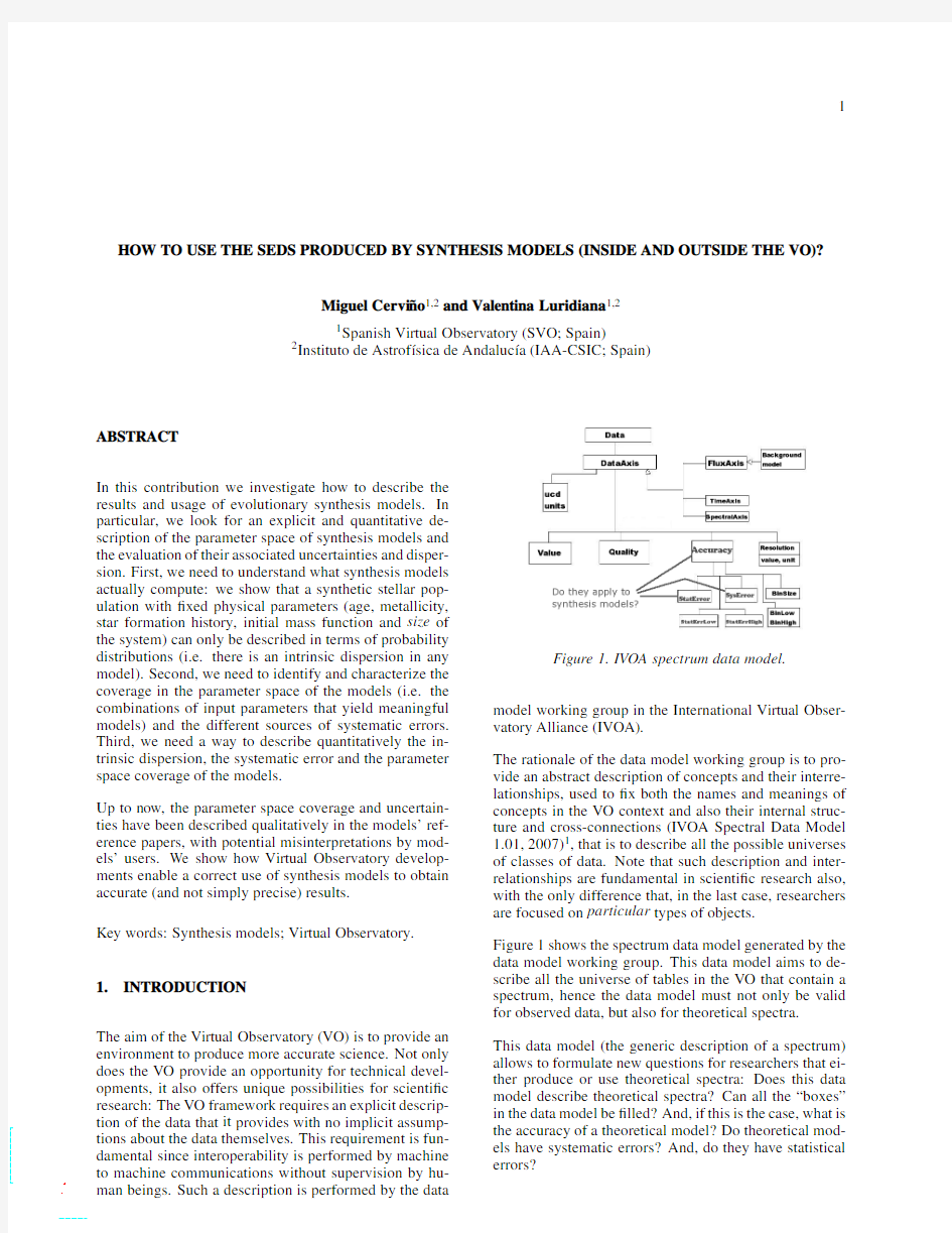
Figure 1.IVOA spectrum data model.
model working group in the International Virtual Obser-vatory Alliance (IVOA).
The rationale of the data model working group is to pro-vide an abstract description of concepts and their interre-lationships,used to ?x both the names and meanings of concepts in the VO context and also their internal struc-ture and cross-connections (IVOA Spectral Data Model 1.01,2007)1,that is to describe all the possible universes of classes of data.Note that such description and inter-relationships are fundamental in scienti?c research also,with the only difference that,in the last case,researchers are focused on particular types of objects.
Figure 1shows the spectrum data model generated by the data model working group.This data model aims to de-scribe all the universe of tables in the VO that contain a spectrum,hence the data model must not only be valid for observed data,but also for theoretical spectra.This data model (the generic description of a spectrum)allows to formulate new questions for researchers that ei-ther produce or use theoretical spectra:Does this data model describe theoretical spectra?Can all the “boxes”in the data model be ?lled?And,if this is the case,what is the accuracy of a theoretical model?Do theoretical mod-els have systematic errors?And,do they have statistical errors?
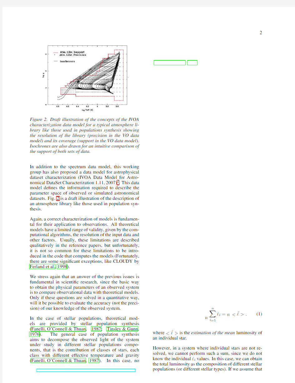
Figure 2.Draft illustration of the concepts of the IVOA characterization data model for a typical atmosphere li-brary like those used in populations synthesis showing the resolution of the library (precision in the VO data model)and its coverage (support in the VO data model).Isochrones are also drawn for an intuitive comparison of the support of both sets of data.
In addition to the spectrum data model,this working group has also proposed a data model for astrophysical dataset characterization (IVOA Data Model for Astro-nomical DataSet Characterization 1.11,2007)2
.
This data
model de?nes the information required to describe the parameter space of observed or simulated astronomical datasets.Fig.2is a draft illustration of the description of an atmosphere library like those used in population syn-thesis.
Again,a correct characterization of models is fundamen-tal for their application to observations.All theoretical models have a limited range of validity,given by the com-putational algorithms,the resolution of the input data and other https://www.doczj.com/doc/4613384632.html,ually,these limitations are described qualitatively in the reference papers,but unfortunately,it is not so common for these limitations to be intro-duced in the code that computes the models (Fortunately,there are some signi?cant exceptions,like CLOUDY by Ferland et al.,1998).
We stress again that an answer of the previous issues is fundamental in scienti?c research,since the basic way to obtain the physical parameters of an observed system is to compare observational data with theoretical models.Only if these questions are solved in a quantitative way,will it be possible to evaluate the accuracy (not the preci-sion)of our knowledge of the observed system.In the case of stellar populations,theoretical mod-els are provided by stellar population synthesis (Fanelli,O’Connell &Thuan,1987;Tinsley &Gunn,1976).The general case of population synthesis aims to decompose the observed light of the system under study in different stellar populations compo-nents,that is the contribution of classes of stars,each class with different effective temperature and gravity (Fanelli,O’Connell &Thuan,1987).In this case,no
n
n i =1
?i =n
>.(1)
where
>is the estimation of the mean luminosity of an individual star.
However,in a system where individual stars are not re-solved,we cannot perform such a sum,since we do not know the individual ?i values.In this case,we can obtain the total luminosity as the composition of different stellar populations (or different stellar types).If we assume that
Figure3.Mean spectrum and90%con?dence interval region of clusters with105M⊙transformed into stars, with a given metallicity and a given age.
a given stellar type i can be represented by a luminos-ity l i and we have some rules that give us the proportion w i between different stellar types for different physical parameters(w i=w i[t,Z,IMF,SFH]),then
L theo
tot (n)=n
N class
i=1
w i l i=n,(2) N class
i=1
w i=1.(3)
whereis the mean(or average)luminosity of an average star that represents the ensemble.Note that this mean luminosity is not necessarily the luminosity of any real star,but it is a description of an underlying prob-ability distribution of the possibles luminosities of real stars in the ensemble.As a trivial example,remember the half-alive half-dead Schr¨o dinger’s cat solution in quan-tum mechanics.
Although Eq.
1and Eq.2look similar,they do not pro-vide the same quantity:The?rst case is the actual inte-grated luminosity of a given cluster and the second case is the mean integrated luminosity of all the possible clus-ters with n stars and in the same evolutionary conditions. Note also that the problem in population synthesis is not the classical statistical one of estimating n,but the inverse one:obtaining the possible theoretical n values compatible with the observed integrated luminos-ity L tot.So,it is necessary to use the complete distribu-tion of theoretical integrated luminosities rather than its
mean value L theo
tot (n).This distribution provides a metric
for goodness-of-?t to stellar population studies.
As an illustration of the effects of this intrinsic disper-sion,we show in Fig.3the90%con?dence interval of the integrated luminosity of a stellar cluster with105M⊙transformed into stars for a given stellar birth rate,metal-licity and age.It represents the integrated spectrum of all Figure4.Mean spectrum of clusters with105M⊙trans-formed into stars,with a given metallicity and a wide range of ages.
possible clusters with this number of stars,and evolution-ary conditions.Fig.4show the mean spectrum of a clus-ter with similar conditions but different ages.The90% con?dence interval in Fig.3,with a single age,covers all the region de?ned by the mean values of the spectra at different ages.Any?t of a real spectrum of such a clus-ter would produce a very precise result for the age,but the accuracy of this?t cannot be known if the underly-ing probability distributions of integrated luminosities at different ages are not taken into account.
We refer to Cervi?n o&Luridiana(2006)for a more ex-tensive analysis of the probabilistic formulation of pop-ulation synthesis and Cervi?n o&Luridiana(2007b)for a more complete description about the metrics for good-ness of?t.
3.SYSTEMATIC ERRORS IN SYNTHESIS MOD-
ELS
Once the origin of the intrinsic dispersion of population synthesis models has been described,we are going to dis-cuss the sources of systematic errors and how to take advantage of the IVOA Characterization data model to de?ne the region of application of synthesis models in its parameter space.We refer to Cervi?n o&Luridiana (2007a)for a more complete review on the systematic er-rors.
In the following,we will only consider the systematic er-rors related to stellar population synthesis computations itself,assuming that the systematic errors of the inputs are known.The main source of systematic errors are: 1.Atmosphere libraries l i:systematic errors in atmo-
sphere libraries mainly depend on how realistic our assumption about the classi?cation of stars in the different stellar types are(see Garc′?a-Vargas’et al.
contribution in these proceedings).Such an evalua-tion must be implemented by synthesis models mak-ers.
In addition to the systematic errors,the range of ap-plication of synthesis models depends in the cover-age on the parameter space(log g,T e?,metallicity, ...),that is the characterization of the library in this parameter space.
2.Tracks/Isochrones and their combination with the
star formation history n i:In the case of synthe-sis models,the shape of isochrones and the den-sity of stars along the isochrone must?t observa-tional data.Small variations in these densities can produce big differences in the models.Hence,it is crucial to know the uncertainties in the evolutionary tracks/isochrones used to evaluate the systematic er-ror in synthesis models.Currently,there are differ-ent groups working on the evaluation of systematic errors in evolutionary tracks,like Degl’Innocenti et al.and Bressan et al.
Additionally,since synthesis models describe the whole population,they also need to take into ac-count evolutionary phases that are included in stan-dard evolutionary tracks,like pre-main sequence evolution,?nal evolutionary stages like SN or cool-ing white dwarfs,etc.In general,synthesis models makers combine tracks of different groups to obtain
a good coverage in evolutionary phases,but in doing
so,they include a potential source of error due to dif-ferent physics used in track computations.The eval-uation of the associated systematic errors and the coverage of the models results due to these effects must be implemented by synthesis models makers.
3.Synthesis models algorithms:the?nal issue is the
algorithms used in the model.The main problem is how to combine the different coverage and sam-pling(support and precision respectively,following the Characterization data model)of the atmosphere libraries and isochrones in the log g?log T e?plane (see Fig.2).In some cases,it is necessary to extrap-olate the behavior of atmosphere libraries to regions not covered by the libraries.In addition,there are also differences in how the correspondence of the points in the isochrones and in the atmosphere li-braries is done,ranging from how the libraries are interpolated to how the closest model to the given isochrone point is chosen.
Although the characterization of synthesis models is a task under development,it is currently possible to de-?ne its range of application by comparing the coverage of isochrones and atmosphere libraries and using the IVOA characterization data model for this task.It will not be the?nal solution of the problem of coverage,but it will enormously help towards the use of synthesis models in their correct range of application.4.CONCLUSIONS
Synthesis models,as any other theoretical model,are af-fected by systematic errors.Although the evaluation of such errors is a dif?cult task that only can be performed by synthesis models makers,the current IVOA descrip-tion of spectrum data model allows to add these errors to the output.
In the case of statistical errors,the spectral data model does not apply directly to theoretical results since the goal of statistics is inferring the underlying distribution from which the data have been drawn,which is assumed to be known in the computation of theoretical models.How-ever,the StatError box in the current spectral data model can be used to describe the intrinsic dispersion of theo-retical models.The dispersion of synthesis models,al-though not recognized as such,is computed by several codes under the label of surface brightness?uctuations, so this piece of information is already available. Finally,a proper characterization of isochrones and at-mosphere libraries coverage allows to obtain a realistic characterization of synthesis models,and its range of ap-plication.
ACKNOWLEDGMENTS
This research has made use of the Spanish Virtual Ob-servatory supported by the Spanish MCyT through grants AyA2005-04286and AyA2005-24102-E.It has also been supported by the Spanish MCyT through the project AYA2004-02703.MC is supported by a Ram′o n y Cajal fellowship.
REFERENCES
Cervi?n o,M.&Luridiana,V.2006,A&A451,475
Cervino,M.,&Luridiana,V.in Resolved Stellar Pop-ulations,D.Valls-Gabaud&M.Chavez(eds.),ASP Conf.Ser.in press,astro-ph/0510411
Cervino,M.,&Luridiana,V.in New quests in stellar astrophysics II2007,in press.
Fanelli,M.N.,O’Connell,R.W.and Thuan,T.X.1987, ApJ321,768
Ferland,G.J.,et al.1998,PASP,110,761
Tinsley,B.M.and Gunn,J.E.1976,ApJ203,52
第 1 页 / 共 40 页 2010年6月25日更新 SYN6288中文语音合成芯片 数据手册 北京宇音天下科技有限公司 地址:北京市海淀区上地高新技术区 010-******** 010-******** https://www.doczj.com/doc/4613384632.html,
第 2 页 / 共 40 页 2010年6月25日更新 目 录 目 录.......................................................................................................................................................................2 1.概述 (4) 1.1 产品应用范围..................................................................................................................................................4 1.2 功能特点..........................................................................................................................................................4 1.3 产品功能描述..................................................................................................................................................5 1.4 合成效果..........................................................................................................................................................6 1.5 系统构成框图..................................................................................................................................................6 1.6 封装信息..........................................................................................................................................................7 1.7 IC 引脚结构.. (8) 1.7.1 纵向引脚视图......................................................................................................................................8 1.7.2 横向引脚视图......................................................................................................................................8 1.7.3 引脚定义. (9) 2.芯片控制方式 (10) 2.1 控制命令........................................................................................................................................................10 2.2 芯片回传.. (11) 3.通讯方式 (11) 3.1 异步串行通讯(UART)接口........................................................................................................................12 3.2 通讯传输字节格式. (12) 4.通信帧定义及通信控制 (12) 4.1 命令帧格式....................................................................................................................................................12 4.2 芯片支持的控制命令....................................................................................................................................13 4.3 命令帧相关的特别说明.. (14) 4.3.1 休眠与唤醒说明................................................................................................................................14 4.3.2 设置波特率说明................................................................................................................................14 4.3.3 其它特别说明....................................................................................................................................15 4.4 命令帧举例. (15) 4.4.1 语音合成播放命令............................................................................................................................15 4.4.2 设置波特率命令................................................................................................................................16 4.4.3 停止合成命令....................................................................................................................................17 4.4.4 暂停合成命令....................................................................................................................................17 4.4.5 恢复合成命令....................................................................................................................................18 4.4.6 芯片状态查询命令............................................................................................................................18 4.4.7 芯片进入Power Down 模式命令. (18) 5. 文本控制标记 (18) 5.1 文本控制标记列表........................................................................................................................................19 5.2 文本控制标记使用示例.. (20) 5.2.1标记[v?] --前景播放音量...............................................................................................................20 5.2.2标记[m?]--背景音乐音量.................................................................................................................21 5.2.3标记[t?] ---词语语速 (21)
语音识别技术 概述 语音识别技术,也被称为自动语音识别Automatic Speech Recognition,(ASR),其目标是将人类的语音中的词汇内容转换为计算机可读的输入,例如按键、二进制编码或者字符序列。与说话人识别及说话人确认不同,后者尝试识别或确认发出语音的说话人而非其中所包含的词汇内容。语音识别技术的应用包括语音拨号、语音导航、室内设备控制、语音文档检索、简单的听写数据录入等。语音识别技术与其他自然语言处理技术如机器翻译及语音合成技术相结合,可以构建出更加复杂的应用,例如语音到语音的翻译。语音识别技术所涉及的领域包括:信号处理、模式识别、概率论和信息论、发声机理和听觉机理、人工智能等等。 历史 早在计算机发明之前,自动语音识别的设想就已经被提上了议事日程,早期的声码器可被视作语音识别及合成的雏形。而1920年代生产的"Radio Rex"玩具狗可能是最早的语音识别器,当这只狗的名字被呼唤的时候,它能够从底座上弹出来。最早的基于电子计算机的语音识别系统是由A T&T贝尔实验室开发的Audrey语音识别系统,它能够识别10个英文数字。其识别方法是跟踪语音中的共振峰。该系统得到了98%的正确率。到1950年代末,伦敦学院(Colledge of London)的Denes已经将语法概率加入语音识别中。1960年代,人工神经网络被引入了语音识别。这一时代的两大突破是线性预测编码Linear Predictive Coding (LPC),及动态时间弯折Dynamic Time Warp技术。语音识别技术的最重大突破是隐含马尔科夫模型Hidden Markov Model的应用。从Baum提出相关数学推理,经过Labiner等人的研究,卡内基梅隆大学的李开复最终实现了第一个基于隐马尔科夫模型的大词汇量语音识别系统Sphinx。[1]。此后严格来说语音识别技术并没有脱离HMM框架。尽管多年来研究人员一直尝试将“听写机”推广,语音识别技术在目前还无法支持无限领域,无限说话人的听写机应用。 模型 目前,主流的大词汇量语音识别系统多采用统计模式识别技术。典型的基于统计模式识别方法的语音识别系统由以下几个基本模块所构成信号处理及特征提取模块。该模块的主要任务是从输入信号中提取特征,供声学模型处理。同时,它一般也包括了一些信号处理技术,以尽可能降低环境噪声、信道、说话人等因素对特征造成的影响。统计声学模型。典型系统多采用基于一阶隐马尔科夫模型进行建模。发音词典。发音词典包含系统所能处理的词汇集及其发音。发音词典实际提供了声学模型建模单元与语言模型建模单元间的映射。语言模型。语言模型对系统所针对的语言进行建模。理论上,包括正则语言,上下文无关文法在内的各种语言模型都可以作为语言模型,但目前各种系统普遍采用的还是基于统计的N元文法及其变体。解码器。解码器是语音识别系统的核心之一,其任务是对输入的信号,根据声学、语言模型及词典,寻找能够以最大概率输出该信号的词串。从数学角度可以更加清楚的了解上述模块之间的关系。首先,统计语音识别的最基本问题是,给定输入
2.1音箱的基本原理和维修方法 2.1音箱的基本原理和维修方法的文章,此文章力求通俗易懂,让刚入门的朋友也能理解2。1音响的工作原理。并快速掌握音响检修的方法。 近日翻阅最新的2005年《电子报》合订本,偶然间发现了漫步者R201T原理图纸。此图纸是南京的刘怀玉先生根据电路板实物描绘出来的。因原作者只简单介绍了一下R201T的参数,并没有工做原理的详细介绍。在这里,我想借助此参考图纸。对漫步者R201T的工做原理做一介绍,并介绍几种实用的维修方法,此文对于磨机爱好者同样适用。 工作原理,如图纸所示:主要分为三部分。分别为电源电路、卫星箱功放电路、超重低音电路. 一、电源电路(图纸的最下面部分):220V市电经过保险管(F),和开关S后进入变压器初级,变压器的次级输出双12V交流,双12V送入由VD1组成的桥式整流电路电路,经过桥式整流和C14,C15(3300UF/25V)的滤波后,输出的空载电压约为正负16V左右(根号2乘于12V),即A+为正16V,A-为负16V。正负16V为三块功放芯片TDA2030,UTC2030提供电源。另一路经过R21、R22的降压后,由B+,B-输出约正负12V为低音前置放大和低通滤波器IC4提供电源电压。 在本图纸当中,前置放大的供电并没有采用78/7912三端稳压电路,磨机爱好者在更换两个3300UF 电容时,也可以考虑加入LM7812/7912为前置提供更为稳定的工作电压。 二、左右声道放大电路(卫星箱功放电路),因左右声道作原理完全一致。这里我只以图纸的左声道为例,作个介绍。如图:RIN为信号输入端,经过耦合电容C23进入音量电位器,(音量电位器由三个引脚,与C23连接的是输入端,输出端也叫滑动端、另一引脚为接地端),调整音量后信号进入由R1/C3组成的高音提升电路,此电路可以提升一定量的高频信号,使声音更加清晰。尔后信号经过耦合电容C1进入左声道功放,型号为UTC2030的1脚,经过功率放大后,由2030的第四脚输出,推动卫星箱发声。图中的
第 1 页 / 共 39 页 2011年9月6日更新 SYN6288中文语音合成芯片 数据手册 北京宇音天下科技有限公司 地址:北京市海淀区上地高新技术区 010-******** 010-******** https://www.doczj.com/doc/4613384632.html,
第 2 页 / 共 39 页 2011年9月6日更新 目 录 目 录.......................................................................................................................................................................2 1.概述 (4) 1.1 产品应用范围..................................................................................................................................................4 1.2 功能特点..........................................................................................................................................................4 1.3 产品功能描述..................................................................................................................................................5 1.4 合成效果..........................................................................................................................................................6 1.5 系统构成框图..................................................................................................................................................6 1.6 封装信息..........................................................................................................................................................7 1.7 IC 引脚结构.. (8) 1.7.1 纵向引脚视图......................................................................................................................................8 1.7.2 横向引脚视图......................................................................................................................................8 1.7.3 引脚定义. (9) 2.芯片控制方式 (10) 2.1 控制命令........................................................................................................................................................10 2.2 芯片回传.. (11) 3.通讯方式 (11) 3.1 异步串行通讯(UART)接口........................................................................................................................12 3.2 通讯传输字节格式. (12) 4.通信帧定义及通信控制 (12) 4.1 命令帧格式....................................................................................................................................................12 4.2 芯片支持的控制命令....................................................................................................................................13 4.3 命令帧相关的特别说明.. (14) 4.3.1 休眠与唤醒说明................................................................................................................................14 4.3.2 设置波特率说明................................................................................................................................14 4.3.3 其它特别说明....................................................................................................................................14 4.4 命令帧举例. (15) 4.4.1 语音合成播放命令............................................................................................................................15 4.4.2 设置波特率命令................................................................................................................................16 4.4.3 停止合成命令....................................................................................................................................17 4.4.4 暂停合成命令....................................................................................................................................17 4.4.5 恢复合成命令....................................................................................................................................17 4.4.6 芯片状态查询命令............................................................................................................................18 4.4.7 芯片进入Power Down 模式命令. (18) 5. 文本控制标记 (18) 5.1 文本控制标记列表........................................................................................................................................18 5.2 文本控制标记使用示例.. (20) 5.2.1标记[v?] --前景播放音量...............................................................................................................20 5.2.2标记[m?]--背景音乐音量.................................................................................................................20 5.2.3标记[t?] ---词语语速 (21)
语音识别改进方法及难点分析 ——《模式识别》结课小论文 学院:化工与环境学院 学号:2120151177 姓名:杜妮
摘要:随着计算机技术的不断发展,人工智能程度也越来越高,作为人工智能的一部分——模式识别也在模型和算法上愈发成熟。本文根据近105年文献,分析最新声音识别的方法和应用。 关键字:模式识别声音识别方法应用 随着人工智能的迅速发展,语音识别的技术越来越成为国内外研究机构的焦点。人们致力于能使机器能够听懂人类的话语指令,并希望通过语音实现对机器的控制。语音识别的研究发展将在不远的将来极大地方便人们的生活。 语音识别大致的流程包括:特征提取、声学模型训练、语音模型训练以及识别搜索算法。作为一项人机交互的关键技术,语音识别在过去的几十年里取得了飞速的发展,人们在研究和探索过程中针对语音识别的各部流程进行了各种各样的尝试和改造,以期发现更好的方法来完成语音识别流程中的各步骤,以此来促进在不同环境下语音识别的效率和准确率。本文通过查阅近10年国内外文献,分析目前语音识别流程中的技术进展和趋势,并在文章最后给出几项语音识别在日常生活中的应用案例,从而分析语音识别之后的市场走势和实际利用价值。 一、语音识别的改进方法 (一)特征提取模块改进 特征提取就是从语音信号中提取出语音的特征序列。提取的语音特征应该能完全、准确地表达语音信号,特征提取的目的是提取语音信号中能代表语音特征的信息,减少语音识别时所要处理的数据量。语音信号的特征分析是语音信号处理的前提和基础,只有分析出可以代表语音信号本质特征的参数,才能对这些参数进行高效的语音通信,语音合成,和语音识别等处理,并且语音合成的好坏,语音识别率的高低,也都取决于语音特征提取的准确性和鲁棒性。目前,针对特定应用的中小词汇量、特定人的语音识别技术发展已较为成熟,已经能够满足通常应用的要求,并逐步投入了实用。而非特定人、大词汇量、连续语音识别仍是
TEA2025是欧洲生产的双声道功率放大集成电路,该电路具有声道分离度高、电源接通时冲击噪声小、外接元件少,最大电压增益可由外接电阻调节等特点,应用于袖珍式或便携式立体声音响系统中作功率放大。 1.TEA2025内电路方框图及引脚功能 TEA2025集成块内部主要由两路功能相同的音频预放、功放、去耦、驱动电路、供电电路等组成,其集成块的内电路方框图及双声道应用电路如图所示。该IC采用16脚双列直插式封装,其集成电路的引脚功能及数据见表所列。
2.TEA2025主要电参数 (1)极限使用条件。电源电压Vcc=15V,输出峰值电流10=1.5A。 (2)主要电参数。TEA2025集成电路工作电源电压范围为3--12 V.典型工作电压6-9 V。在Vcc=9 V,RL=8。Ta=25℃条件下,有以下主要电参数。 静态电流ICQ 最大值为50 mA,典型值为40 mA。 电压增益GV 双声道时的最大值为47 dB,最小值为43 dB,典型值为45 dB;BTL时的最大值为53 dB,最小值为49 dB,典型值为51 dB。
输出功率PO 当THD=10%,P=1 kHz时,双声道时的典型值为1.3 W,BTL时的典型值为4.7 W。 谐波失真THD 当F=1 kHz,Po=250 mW,RL=4。时,双声道时的最大值为1.5%,典型值为0.3%; BTL时的典型值为0.5%. 3.TEA2025典型应用电路 TEA2025集成电路的输出功率由电源电压和负载阻抗大小决定。既可以构成双声道功放,又可以组成BTL功放。其集成块的双声道典型应用电路如图所示,其集成块的BTL典型应用电路如图所示。 4.电路工作过程 以双声道电路为例,音频信号经电容祸合从TEA2025的⑦、⑩脚输入,先经预放大后加到功率放大器,放大后的音频信号从②、15脚输出,由输出祸合电容耦合去驱动喇叭发声。
SYN6288语音播放模块制作 1、SYN6288语音芯片封装图: 2、通信方式: 异步串行通讯(UART)接口 SYN 6288 提供一组全双工的异步串行通讯(UART)接口,实现与微处理器或PC 的数据传输。SYN 6288利用TxD 和RxD 以及GND 实现串口通信。其中GND 作为地信号。SYN 6288 芯片支持UART 接口通讯方式,
通过UART 接口接收上位机发送的命令和数据,允许发送数据的最大长度为206 字节。通讯传输字节格式 1、初始波特率:9600 bps 2、起始位: 1 3、数据位:8 4、校验位:无 5、停止位:1 6、流控制:无 与51单片机通信时,可以用单片机的串行通信方式1。 3、硬件电路搭建: 外接电源组接法 备注:SYN 6288共有6组外接电源,每组电源均使用一个47uF和一个的电容;如果用户想节省成本,用户可以在每组电源上均使用的电容,并对VDDPP、和VDDA两组电源,各加上一47uF的电容。
复位电路及状态指示电路 备注:Ready/Busy 此STATUS引脚信号为低电平时说明芯片正在等待接收数据。在系统设计时可以将此引脚接 在MCU的中断输入源上,产生一个下降沿中断请求发送数据,以示上位机MCU可以向语音合成芯片发送数据。 SYN6288 的扬声器输出 (1)为了在用户应用中输出声音, SYN6288 内置了推挽 式(Push-Pull)的DAC ,可直接驱动喇叭,进行 声音播报。并且SYN6288 内置的DAC 电路模块, 使用了VDDPP/VSSPP 供电电源模块,具体电路说 明部分请参见和节,其供电电压值可独 立于其它电源组的供电。(见右图) SYN6288 外接高速晶振
关于语音识别的研究 网络工程专业网络C071班贾鸿姗 076040 摘要:语音识别技术的广泛应用 1前言: 语音识别技术也被称为自动语音识别 (ASR),其目标是将人类的语音中的词汇内容转换为计算机可读的输入,例如按键、二进制编码或者字符序列。与说话人识别及说话人确认不同,后者尝试识别或确认发出语音的说话人而非其中所包含的词汇内容。语音识别是一门交叉学科。近二十年来,语音识别技术取得显著进步,开始从实验室走向市场。人们预计,未来10年内,语音识别技术将进入工业、家电、通信、汽车电子、医疗、家庭服务、消费电子产品等各个领域。语音识别技术所涉及的领域包括:信号处理、模式识别、概率论和信息论、发声机理和听觉机理、人工智能等等。 早在计算机发明之前,自动语音识别的设想就已经被提上了议事日程,早期的声码器可被视作语音识别及合成的雏形。而1920年代生产的"Radio Rex"玩具狗可能是最早的语音识别器,当这只狗的名字被呼唤的时候,它能够从底座上弹出来。最早的基于电子计算机的语音识别系统是由AT&T 贝尔实验室开发的Audrey语音识别系统,它能够识别10个英文数字。其识别方法是跟踪语音中的共振峰。该系统得到了98%的正确率。。到1950年代末,伦敦学院(Colledge of London)的Denes 已经将语法概率加入语音识别中。 1960年代,人工神经网络被引入了语音识别。这一时代的两大突破是线性预测编码Linear Predictive Coding (LPC),及动态时间弯折Dynamic Time Warp技术。 语音识别技术的最重大突破是隐含马尔科夫模型Hidden Markov Model的应用。从Baum提出相关数学推理,经过Labiner等人的研究,卡内基梅隆大学的李开复最终实现了第一个基于隐马尔科夫模型的大词汇量语音识别系统Sphinx。。此后严格来说语音识别技术并没有脱离HMM框架。 尽管多年来研究人员一直尝试将“听写机”推广,语音识别技术在目前还无法支持无限领域,无限说话人的听写机应用。 2 正文 2.1应用领域 2.1.1.电话通信的语音拨号 特别是在中、高档移动电话上,现已普遍的具有语音拨号的功能。随着语音识别芯片的价格降低,普通电话上也将具备语音拨号的功能。 2.1.2.汽车的语音控制 由于在汽车的行驶过程中,驾驶员的手必须放在方向盘上,因此在汽车上拨打电话,需要使用具有语音拨号功能的免提电话通信方式。此外,对汽车的卫星导航定位系统(GPS)的操作,汽车空调、照明以及音响等设备的操作,同样也可以由语音来方便的控制。 工业控制及医疗领域。当操作人员的眼或手已经被占用的情况下,在增加控制操作时,最好的办法就是增加人与机器的语音交互界面。由语音对机器发出命令,机器用语音做出应答。 2.1.3数字助理 个人数字助理(Personal Digital Assistant,PDA)的语音交互界面。PDA的体积很小,人机界面一直是其应用和技术的瓶颈之一。由于在PDA上使用键盘非常不便,因此,现多采用手写体识别的方法输入和查询信息。但是,这种方法仍然让用户感到很不方便。现在业界一致认为,PDA的最佳人机交互界面是以语音作为传输介质的交互方法,并且已有少量应用。随着语音识别技术的提高,可以预见,在不久的将来,语音将成为PDA主要的人机交互界面。 智能玩具 通过语音识别技术,我们可以与智能娃娃对话,可以用语音对玩具发出命令,让其完成一些简单的任务,甚至可以制造具有语音锁功能的电子看门狗。智能玩具有很大的市场潜力,而其关键在
语音识别研究的背景意义及现状研究的背景及意义 自从人类可以制造和使用各种机器以来,人们就有一个理想,那就是让各种机器能听懂人类的语言并能按人的口头命令来行动,从而实现人机的语言交流。随着科学技术的不断发展,语音识别 (Speech Recognition) 技术的出现,使人类的这一理想得以实现。语音识别技术就是让机器通过识别和理解把语音信号转变为相应的文本或命令的高技术。语音识别是一门交叉学科,语音识别正逐步成为信息技术中人机接口的关键技术,语音识别技术与语音合成技术的结合,使人们能够甩掉键盘,通过语音命令进行操作。语音技术的应用已经成为一个具有竞争性的新兴高技术产业。当今,语音识别产品在人机认交互应用中己经占到越来越大的比例。 音乐就是一种艺术。通常可以解释为一系列对于有声、无声具有时间性的组织,并含有不同音阶的节奏、旋律及和声。音乐与人的生活情趣、审美情趣、言语、行为、人际关系等等,有一定的关联。音乐是人们抒发感情、表现感情、寄托感情的艺术,不论是唱、奏或听,都内涵着关联人们千丝万缕情感的因素。特别对人的心理,会起着不能用言语所能形容的影响作用。 音乐可以通过几种途径来体验,而音乐播放器是现代生活中最便捷 , 最实用的一种。现如今社会在飞速发展,人们的生活节奏也在不断加快,工作压力也在日益增大,致使越来越多的人选择在闲暇时间放松自己。而听音乐就成了人们缓解生活压力的第一选择,医学表明音乐不仅可以对人们紧张的心情带来放松,还能有效的缓解高血压对心血管造成的压力。因此音乐播放器已经成为人们日常生活中至关重要的物品。 然而可惜的是,传统的音乐播放器通常上是通过两种方式实现人们对播放器的控制的:一是按键式控制(其中也包括线控式),通过直接按键改变电平发出指令;二是通过远程控制,通过红外线或者蓝牙等对播放器发布命令。这对于疲劳中的人们或者残障人士来说是不方便的。为了减少手动操作的繁琐,此次设计专门致力于研究一种方案通过语音控制来实现对音乐播放器的控制,使其更加方便、更加人性化,实现音乐播放器的全自动语音控制。这个设计不仅是为了解决人们日常使用传统音乐播放器不方便的烦恼,而且是为了研究语音识别技术在单片机中的应用,特别是在SPCE061中实现语音识别的应用,设计出具有语音控制功能的音乐播放器。 国内外研究现状 语音识别的研究工作可以追溯到 20世纪50年代AT&T贝尔实验室的Audry 系统,它是第一个可以识别十个英文数字的语音识别系统。 但真正取得实质性进展,并将其作为一个重要的课题开展研究则是在 60年代末
SYN6658中文语音合成芯片是北京宇音天下科技有限公司于2012年最新推出的一款性Array /价比更高,效果更自然的一款高端语音合成芯片。SYN6658通过UART接口或SPI接口 通讯方式,接收待合成的文本数据,实现文本到语音(或TTS语音)的转换。 公司最新推出的SYN6658语音合成芯片,继承了OSYNO6188和SYN6288语音芯 片的优秀特点:小尺寸贴片封装、硬件接口简单、低功耗、音色清亮圆润、极高的性/价 比;除此之外,SYN6658在识别文本/数字/字符串更智能、更准确,语音合成自然度上 升了一个大的台阶。SYN6658语音合成效果和智能化程度达到了质的飞跃,是一款真正 面向高端行业应用领域的中文语音合成芯片。 SYN6658语音合成芯片的诞生,将推动TTS语音合成技术的行业应用走向更深入、 LQFP64 10*10*1.4MM 更广泛! 功能特点: ?芯片支持任意中文文本的合成,可以采用GB2312、GBK、BIG5 和Unicode 四种编码方式; ?芯片具有文本智能分析处理功能,对常见的数值、电话号码、时间日期、度量衡符号等格式的文本; ?芯片可以自动对文本进行分析,判别文本中多音字的读法并合成正确的读音; ?芯片可实现10级数字音量控制,音量更大,更广; ?芯片内集成了77首声音提示音和14首和弦音乐; ?提供两男、两女、一个效果器和一个女童声共6个中文发音人; ?支持多种文本控制标记,提升文本处理的正确率; ?支持多种控制命令,包括:合成、停止、暂停合成、继续合成、改变波特率等; ?支持多种方式查询芯片的工作状态; ?两种通讯模式:芯片支持UART、SPI两种通讯方式; ?芯片支持Power Down 模式。使用控制命令可以使芯片进入Power Down 模式; ?芯片支持的通讯波特率:4800bps,9600bps,57600bps、115200bps; ?芯片各项指标均满足室外严酷环境下的应用; 应用范围: ?车载信息终端语音播报,车载调度,车载导航 ?公交报站器,考勤机 ?手机,固定电话 ?排队叫号机,收银收费机 ?自动售货机,信息机,POS 机 ?智能仪器仪表,气象预警机,智能变压器
语音识别技术的现状与未来 The Present and Future of Speech Recognition (CSLT-TRP-20160034) 王东(Dong Wang) 2017/01/08 CSLT, RIIT, Tsinghua Univ.
语音识别任务及其研究意义 语音识别(Automatic Speech Recognition, ASR)是指利用计算机实现从语音到文字自动转换的任务。在实际应用中,语音识别通常与自然语言理解、自然语言生成和语音合成等技术结合在一起,提供一个基于语音的自然流畅的人机交互方法。 早期的语音识别技术多基于信号处理和模式识别方法。随着技术的进步,机器学习方法越来越多地应用到语音识别研究中,特别是深度学习技术,它给语音识别研究带来了深刻变革。同时,语音识别通常需要集成语法和语义等高层知识来提高识别精度,因此和自然语言处理技术息息相关。另外,随着数据量的增加和机器计算能力的提高,语音识别越来越依赖数据资源和各种数据优化方法,这使得语音识别与大数据、高性能计算等新技术产生广泛结合。综上所述,语音识别是一门综合性应用技术,集成了包括信号处理、模式识别、机器学习、数值分析、自然语言处理、高性能计算等一系列基础学科的优秀成果,是一门跨领域、跨学科的应用型研究。 语音识别研究具有重要的科学价值和社会价值。语音信号是典型的局部稳态时间序列,研究这一信号的建模方法具有普遍意义。事实上,我们日常所见的大量信号都属于这种局部稳态信号,如视频、雷达信号、金融资产价格、经济数据等。这些信号的共同特点是在抽象的时间序列中包括大量不同层次的信息,因而可用相似的模型进行描述。历史上,语音信号的研究成果在若干领域起过重要的启发作用。例如,语音信号处理中的隐马尔可夫模型在金融分析、机械控制等领域都得到了广泛应用。近年来,深度神经网络在语音识别领域的巨大成功直接促进了各种深度学习模型在自然语言处理、图形图象处理、知识推理等众多应用领域的发展,取得了一个又一个令人惊叹的成果。 在实用价值方面,语音交互是未来人机交互的重要方式之一。随着移动电话、穿戴式设备、智能家电等可计算设备的普及,基于键盘、鼠标、触摸屏的传统交互方式变得越来越困难。为了解决这种困难,手势、脑波等一系统新的人机交互方式进入人们的视野。在这些五花八门的新兴交互方式中,语音交互具有自然、便捷、安全和稳定等特性,是最理想的交互方式。在语音交互技术中,语音识别是至关重要的一环:只有能“听懂”用户的输入,系统才能做出合理的反应。今天,语音识别技术已经广泛应用在移动设备、车载设备、机器人等场景,在搜索、操控、导航、休闲娱乐等众多领域发挥了越来越重要的作用。随着技术越来越成熟稳定,我们相信一个以语音作为主要交互方式的人机界面新时代将很快到来。 研究内容和关键科学问题 语音识别研究主要包括如下三方面内容:语音信号的表示,即特征抽取;语音信号和语言知识建模;基于模型的推理,即解码。语音信号的复杂性和多变性使得这三方面的研究都面临相当大的挑战。图1给出一个语音识别系统的典型架构。
工作原理,如图纸所示:主要分为三部分。分别为电源电路、卫星箱功放电路、超重低音电路. 一、电源电路(图纸的最下面部分):220V市电经过保险管(F),和开关S后进入变压器初级,变压器的次级输出 双12V交流,双12V送入由VD1组成的桥式整流电路电路,经过桥式整流和C14,C15(3300 UF/25V)的滤波后, 输出的空载电压约为正负16V左右(根号2乘于12V),即A+为正16V,A-为负16V。正负16 V为三块功放芯片 TDA2030,UTC2030提供电源。另一路经过R21、R22的降压后,由B+,B-输出约正负12V为低音前置放大和 低通滤波器IC4提供电源电压。 在本图纸当中,前置放大的供电并没有采用78/7912三端稳压电路,磨机爱好者在更换两个3300 UF电容时,也可以考虑 加入LM7812/7912为前置提供更为稳定的工作电压。 二、左右声道放大电路(卫星箱功放电路),因左右声道作原理完全一致。这里我只以图纸的左声道为例,作个介绍。 如图:RIN为信号输入端,经过耦合电容C23进入音量电位器,(音量电位器由三个引脚,与C 23连接的是输入端, 输出端也叫滑动端、另一引脚为接地端),调整音量后信号进入由R1/C3组成的高音提升电路,此电路可以提升一定量的 高频信号,使声音更加清晰。尔后信号经过耦合电容C1进入左声道功放,型号为UTC2030的1脚,经过功率放大后,由 2030的第四脚输出,推动卫星箱发声。图中的R7为反馈电阻,R7/R9为决定2030芯片的放大倍数。因此,调整R7的阻值 ,就可以调整放大倍数。R11/C7为扬声器补偿网络。 三、超低音电路。由左右声道经两个10K电阻R5、R6后至C11耦合电容,尔后信号进入IC4,型号为JRC4558的3脚,图中 IC4A为超低音的前置放大器。R201T将此放大器的放大倍数设置为6倍左右。(R17/R18),经