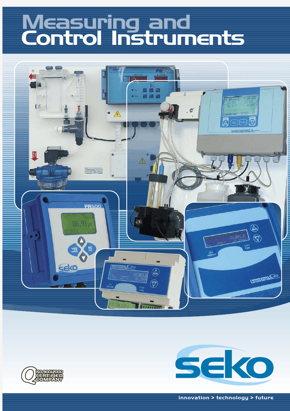

Measuring and Control Instruments
innovation > technology > future
Measuring and control instruments, Probes and Accessories Measuring and control instruments, Probes and Accessories
kontrol 20 pH/Redox and conductivity controllers
pH/Redox Conductivity kontrol PR20 kontrol CD20
3
kontrol 40
pH/Redox and conductivity controllers
pH/Redox Conductivity kontrol PR40 kontrol CD40
4
kontrol 500
pH/Redox, chlorine, conductivity, oxygen and turbidity controllers
pH/Redox Chlorine Conductivity Oxygen Turbidity kontrol kontrol kontrol kontrol kontrol PR500 CL500 CD500 OX500 TB500
6
Assembled Panels
Panels for measuring and setting pH value, Redox potential (ORP) and Chlorine concentration
pH, Redox and Chlorine Chlorine pH and Redox pH and Chlorine kontrol kontrol kontrol kontrol PRC CL PR PC
8
photometer systems Probes
Free and total Chlorine multi-parameter control unit with photometric method, pH, Redox and Temperature 10 pH, Redox and Conductivity Oxygen and Turbidity (for 500 series)
Oxysens - Turby Sensor
12 14 15 16 18
Potentiostatic Chlorine probes (for 500 series)
CL-Sensor
Accessories
pH, Redox and Conductivity probe holder Cables, buffer solutions and probe accessories
2
water treatment division > measuring and control instuments
pH/Redox and conductivity pH/Redoxand conductivity measuring and control instruments measuringand control instruments
kontrol 20
A technologically advanced instrument which allows accurate adjustments of water treatment applications. kontrol PR2 0 pH/Redox kontrol CD20 Conductivity
Selectable measurement scales
Using the programming menu, it is possible to select the available measurement scale to ensure operating versatility with a single instrument.
Easy to read
The instrument displays the chemical measurement and the temperature via the 2-line, 16-character Display.
Standard Functions
? Multilingual menu ? Password protection for setting menu ? Quality indication of measuring probes
Easy to calibrate
This instrument is capable of recognising the buffer solutions, performing automatic calibration for 2 points (7 - 4 or 9.22 pH), stopping the dosage and indicating the state of efficiency of the probe. Conductivity Calibration is performed using a reference value.
Output 4…20mA
The ideal solution for connecting to a logger or data acquisition system.
pH/Redox-meter characteristics
Measurement scales(*) Temperature Resolution Current output(*) Set Points (2 independent) Power supply Panel version (96x96x92 mm) pH: 0÷14,00 Redox: ±1000 mV Precision 1% FS Precision 1% FS 0÷100°C (Precision 1% FS ) with PT100 0/4÷20 ? 20÷4/0 mA (±2%) through 10 A 250 V dry contact relay (resistance load) 100÷240 Vac 50Hz/60Hz (12÷24 AC/DC with accessory cable)
Conductivity-meter characteristics
Measurement scales(*) with K10 probe with K5 probe with K1 probe Temperature Resolution Current output(*) Set Points (2 independent) Power supply
( )
10÷20000 μS 10÷2000 μS ± 1% FS 20÷4000 μS ± 1% FS 100÷20000 μS ±1% FS
Precision 1% FS
0÷100°C (Precision 1% FS ) with PT100 0/4÷20 ? 20÷4/0 mA (±2%) through 10 A 250 V dry contact relay (resistance load) 100÷240 Vac 50Hz/60Hz (12÷24 AC/DC with accessory cable)
* Selectable via software
Wall-mounted Version with IP65 degree protection (144x144x90 mm) innovation > technology > future
Panel version (48x96x100 mm)
DIN Rail Version (6 EN50022 modules) 3
pH/Redox and conductivity pH/Redoxand conductivity measuring and control instruments measuringand control instruments
kontrol 40
A technologically advanced instrument which allows accurate adjustments of applications such as: ? mineral waters ? water treatment ? galvanic processes ? the food industry ? swimming pools ? biotechnologies ? osmosis plants kontrol PR4 0 kontrol CD40 pH/Redox Conductivity
Wall-mounted version with IP65 degree protection (144x144x90 mm) DIN Rail Version (6 EN50022 modules)
Panel version (48x96x100 mm)
Panel version (96x96x92 mm)
4 water treatment division > measuring and control instuments
Standard Functions
? Multilingual menu ? Password protection for setting menu ? Relay activation statistics ? Manual control of all the instrument’s functions ? Quality control of measurement probes ? OFA (Over Feed Alarm): timed excess dosage alarm ? Alarm band can be set with minimum and maximum values ? Proportional dosing through Set Points:
10 Minutes 100% 80% 60% 40% 20% 7,2 7,4 7,6 7,8 8,0 8,2 pH
Galvanic separation of output 4…20mA
The ideal solution for connecting to a logger or data acquisition system without any interference.
Selectable measurement scales
Using the programming menu, it is possible to select the available measurement scale to ensure operating versatility with a single instrument.
Easy to read
The instrument displays the chemical measurement, the temperature and any alarms via the 2-line, 16-character Display.
Proportional Band = 1.0 pH
Voltage input from remote system
The instrument is equipped with a voltage input (ranging from 15 to 30 Vac/Vdc) for suspending the measurement and dosage functions via a remote control system.
Easy to calibrate
This instrument is capable of recognising the buffer solutions, performing automatic calibration for 2 points (7 - 4 or 9.22 pH), stopping the dosage and indicating the state of efficiency of the probe. Conductivity Calibration is performed using a reference value.
pH/Redox-meter characteristics
Measurement scales(*) Temperature Resolution Set Points (2 independent) Voltage Power supply pH: 0÷14,00 Redox: ±1.000 mV Precision 1% FS Precision 1% FS 0/4÷20 ? 20÷4/0 mA (±2%) Alphanumeric Display 0÷100°C (Precision 1% FS ) with PT100 through 10 A 250 V dry contact relay (resistance load) 15÷30 Vac/Vdc 100÷240 Vac 50Hz/60Hz (12÷24 AC/DC with accessory cable)
Current output(*) (galvanically isolated)
Conductivity-meter characteristics
Measurement scales(*) with K10 probe 1÷50000 μS Precision 1% FS 1÷200 μS ± 1% FS 10÷2000 μS ± 1% FS with K5 probe 20÷4000 μS ± 1% FS with K1 probe 100÷20000 μS ±1% FS 200÷50000 μS ± 1% FS Temperature Resolution 0÷100°C (Precision 1% FS ) with PT100 Current output(*) (galvanically isolated) 0/4÷20 ? 20÷4/0 mA (±2%) Set Points (2 independent) through 10 A 250 V dry contact relay (resistance load) Voltage 15÷30 Vac/Vdc 100÷240 Vac 50Hz/60Hz (12÷24 AC/DC with accessory cable) Power supply
( )
Easy connections
Montaggio DIN DIN Mounting
*Selectable via software
innovation > technology > future
5
pH/Redox, chlorine, conductivity, oxygen pH/Redox, chlorine,conductivity, oxygen and and turbidity measuring and control instruments turbidity measuringand control instruments
kontrol 500
A line of instruments for measurement and control designed specifically for the industrial and water treatment sector. The available measurements are: kontrol PR500 pH/Redox kontrol CL500 Chlorine kontrol CD500 Conductivity kontrol OX500 Oxygen kontrol TB500 Turbidity
Graphic Display
The graphic display with 128x64 pixel resolution allows simultaneous display of the chemical measurement, the temperature measurement and the status of the various control outputs through the graphics of the icon throughout the entire process.
Multilingual Communication
The devices are equipped with a simple mnemonic interface with the option of selecting the communication language from English, French, Spanish, German and Italian.
Control outputs
Each instrument has 2 current outputs and 4 relays allowing management of up to six different peripherals, to create an automatic measurement and control system.
Power-assisted calibration with probe quality control
The software functions designed for the various calibrations with 2 points (7 - 4 or 9.22 pH) provide the operator with effective assistance, always ensuring an excellent operating service and displaying a valuable message about the quality of the probe used.
PID control functions
The instruments are provided with settable software functions to control the Proportional-Integral-Derivative (PID), Timed and Pause-Operation remote devices.
Serial Communication (RS485)
All the devices are equipped for RS485 serial port communication for monitoring measurements and storing data.
Panel version (96x96 mm)
Montaggio DIN
Wall - or pole-mounted panel version with IP65 degree protection (144x144 mm)
6 water treatment division > measuring and control instuments
Measurement scales
kontrol PR500
pH Resolution Redox Resolution 0 ÷ 14 pH 0,01 pH ± 1500 mV 1 mV
Mechanical characteristics
Sizes Box material Degree protection Mounting 144x144x112 mm and 96x96x130 mm ABS (96x96) and PP (144x144) IP65 (144x144) and IP54 (96x96) Wall - Panel - Pole
kontrol CL500
Chlorine Resolution 0÷2 ppm; 0÷5 ppm; 0÷10 ppm; 0÷20 ppm 0,01 ppm
Electrical characteristics
Universal power supply Consumption 80÷265 Vac (24 Vac on request) 10 VA
kontrol CD500
Conductivity (with K1 probe) 0÷20 μS; 0÷200 μS; 0÷2000 μS; 0÷20000 μS Resolution 0,01 μS; 0,1 μS; 1 μS; 10 μS
Control outputs
Double current output galvanically separated Dry contact Dry contact Dry contact RS485 port Double Relay with double exchange for dosing Set Points(*) Relay dedicated to probe cleaning(*) Remote alarm relay *
( )
kontrol OX500
Oxygen Resolution 0÷20 ppm 0,1 ppm
kontrol TB500
Turbidity Resolution 0,00÷1,00 FTU; 0,0÷10,0 FTU; 0÷100 FTU 0,01 FTU; 0,1 FTU; 1 FTU
Serial interface
( )
* (6A 250Vac resistive load)
Common specifications
Temperature -10 °C ÷ +150 °C (+14 °F ÷ +302 °F) Resolution 0,1°C (0,1°F) Measurement accuracy (pH, RX, Cl, CD, O2, Turbidity) 98%
Inputs
Voltage 15÷30 Vac/dc (to keep the instrument in “Hold” mode)
Control functions and settings
Controls 1. PID (available at current output no. 2) 2. Timed 3. ON/OFF
User-Friendly Keyboard
Graphic Display
Descriptive Display
Delay function for relay activation Manual control of all outputs Assisted calibration with probe quality evaluation Set Point value modification with special menu (Quick menu) Setup protection with passwords
Mounted on a pole with a bracket and shelter (accessories)
Interface
Number of keys Graphic Display 4 for setting parameters 128x64 pixels with backlighting
innovation > technology > future
7
Assembled Panels Assembled Panels
Panels for measurement and setting of pH value, Redox potential (ORP) and Chlorine concentration
? Autocalibration of all measurements (pH; Redox; Chlorine) ? Compact probe holder complete with flow sensor, valve for adjusting the flow rate and tap for drawing off the liquid ? Alarm signal water flow lack ? Instrument with IP65 degree of protection ? Two alarm relays (5 A - 250 Vac) ? 4÷20 mA outputs for each parameter measured, with option of selecting the interval
Compact and easy to use, the Kontrol series panels include the accessories required for immediate installation (buffer solutions for pH and Rx calibration, and DPD colorimetric system for CI calibration).
? 230 Vac power supply (standard) or 115 Vac (on request) ? Programmable Set points and alarm ? Pump pause function during the calibration phases ? Temperature reading and compensation (automatic with optional PT100) ? Set point adjustment: On/Off, pause/operation, and proportional pulse regulation
kontrol PRC
Panel for measurement and adjustment of pH value, Redox Potential (ORP) and Chlorine concentration Consisting of: ? PC95 and PR40 instruments ? pH and Redox (ORP) probes ? Probe holder complete with self-cleaning amperometric cell (Pt-Cu) ? Mechanical filter on water input ? Solenoid valve to shut off the water flow for autocalibration This instrument allows autocalibration directly with the chemical and physical characteristics of the water to be measured, and indicates the quality of the probes Measurement scales 0÷5,00 ppm Free Chlorine / 0÷14,00 pH / ±999 mV Redox
8
water treatment division > measuring and control instuments
kontrol CL
Panel for measuring and adjustment of Chlorine concentration Consisting of: ? Probe holder complete with self-cleaning amperometric cell (Pt-Cu) ? Mechanical filter on water input ? Solenoid valve to shut off the water flow for autocalibration This instrument allows autocalibration directly with the chemical and physical characteristics of the water to be measured and indicates the quality of the probes Measurement scales 0÷5,00 ppm Free Chlorine
kontrol PR
Panel for measurement and adjustment of pH value and Redox Potential (ORP) Consisting of: ? PR95 instrument ? pH and Redox (ORP) probes ? Probe holder ? Mechanical filter on water input The instrument indicates the quality of the probes Measurement scales 0÷14,00 pH / ±999 mV Redox
kontrol PC
Panel for measurement and adjustment of pH value and Chlorine concentration Consisting of: ? PC95 instrument ? pH probe ? Probe holder complete with self-cleaning amperometric cell (Pt-Cu) ? Mechanical filter on water input ? Solenoid valve to shut off the water flow for autocalibration This instrument allows autocalibration directly with the chemical and physical characteristics of the water to be measured and indicates the quality of the probes Measurement scales 0÷14,00 pH / 0÷5,00 ppm Free Chlorine
innovation > technology > future
9
Free and total chlorine multi-parameter control unit wi Free and total chlorine multi-parameter control unit wit
photometer system
In response to the recent market demand for compact, easy-to-use, low-maintenance systems. The system is equipped with a graphic display subdivided into areas for simultaneous display of all the required measurements. The removable cover guarantees the accessibility of the system and also allows: G Protection of the chemical reagents from ultraviolet rays G High display visibility in the event of incident light
G IP65 container protects from humid environments G User-friendly interface with messages in various languages. The wide display allows the creation of graphics for each available measurement thanks to the internal Data Logger function.
The peristaltic pump, which has 4 pressure points, saves on reagents
G Mechanics with “flip door” permitting easy access to the electrical connections G BNC connectors on side of box facilitate quick maintenance of the pH and Redox probes
Continual monitoring of reagents using level probes
The DPD reagent in powder form, to be diluted before use, is an excellent solution for safely storing the product in any location
10
water treatment division > measuring and control instuments
th photometric method, pH, Redox and Temperature ith photometric method, pH, Redox and Temperature
G Hydraulics with outlet of water containing reagents for chlorine measurement. This allows a considerable reduction in the quantity of water used for the measurement. The water used for checking the pH and Redox can be channelled towards the buffer tank, while only the water polluted by the DPD reagents will be drained off and managed separately in accordance with local regulations G Installation time reduced thanks to quick-coupling connections for sampling and outlet pipes G The Unit has self-calibration for optical unit and ensures a high level of Chlorine measurement precision using a 520 nm sensor and light source emitted by a LED
Probe holder Clean water inlet Special Outlet for water with DPD reagent Clean water outlet
Technical Characteristics
Free or total chlorine pH Redox Temperature Display Programming Digital Input Analogue Input Power supply Internal Data Logger Measurement 0÷ 5,00 ppm Measurement 0÷14,00 pH Measurement ±1500 mV Measurement 0÷50 °C 240x128 pixel backlit graphic Via keypad with 4 bubble keys Dry contact for disabling dosages 0/4÷20 mA for auxiliary measurements 90÷264Vac 50-60Hz 66 Watt Flash Memory 16,000 records Recording interval 00:00 ÷ 99:99 minutes Type circular / refill Tabular / graphic display Size Chlorine, pH, Redox, Temperature Type 0/4÷20 mA galvanically separated Lower / upper / inversion limit programming Maximum load 500 Ohms nr. 2 per measurement di Cloro + nr. 2 per measurement pH Max. relay load 3A (resistive) 230Vac Lack of sample water Reagents run out Floodlight burned out Dirty cell Relay max. resistive load 3A at 230Vac Programmable as Set Points for Redox measurement, Set Points for Temperature measurement, Timed activation for cell cleaning Relay max. resistive load 3A at 230Vac RTU MODBUS protocol with programmable Baud rate 1200 ÷ 38400 Total Chlorine + Temperature Free chlorine + Temperature Free chlorine+ pH + Temperature Free chlorine + pH + Redox + Temperature Resolution 0,01ppm Resolution 0,01 pH Resolution 1 mV Resolution 0.1°C Precision 1% FS Precision 1% FS Precision 1% FS Precision 1% FS
4 Analogue Outputs
4 Set Point Relay Outputs Alarm Relay Output
2 Auxiliary Relay Outputs
Serial Port Output (RS485)
Products
innovation > technology > future
11
pH/Redox and conductivity probes pH/Redoxand conductivity probes
pH/Redox Probes
pH and Redox measurements take place through the transformation of a chemical phenomenon into electrical potential which is read by a special sensor called a probe. Probes are active elements with a limited lifespan and must be periodically calibrated with known solutions (buffer solutions). The probes illustrated below are all of the combined type (Measurement + Reference) and are classified by their chemical and physical characteristics which make them suitable for multiple applications. The following elements must be considered when choosing a probe: field of measurement , temperature, pressure, chemical substances present during the process and type of mounting within the system.
Series 3-4 PG 13.5 S7
Series 1 with cable+BNC
Conductivity Probes
Standard BNC Boot
Our range of conductivity probes is specially designed for use in industrial environments in conjunction with our measurement instruments. The various available models make it possible to cover an extremely wide measurement range. There are versions with temperature sensors and special versions with graphite or platinum probes, PTFE cell bodies and IP67 connectors. Measurement of conductivity is performed by dipping the two metallic electrodes of the probe in the solution to be measured. The passage of the current between the two electrodes allows the electrical resistance of the liquid, and therefore its conductivity, to be measured. The measurement is influenced by the temperature. In saline solutions, measurement variations of 2% / °C can occur. This variation can even reach 7% / °C. Therefore, conductivity probes without temperature sensors should only be used if the solution being tested is maintained at a temperature between 15°C and 25 °C, making an error of approximately 10%. Note All the models are guaranteed for a maximum pressure of 6 bars.
without temperature sensor
CT-K1
C-K1-PT CT-K1-SS C-K1 C-K5 C-K10 CT-K5 CT-K1-G
CT-K1-GR with temperature sensor 12 CT-K10
water treatment division > measuring and control instuments
Model
Range Min Measur. Conduc.
Max Temp.
Max Press.
Porous septum
Ref.
Connection
Mounting onto the process
Material Body
General applications
SPH-1-S1,5 SPH-1-S6 SPH-3-WW SPH-4-HP SPH-4-HT SPH-4-LC 0÷14 pH 0÷14 pH 2÷14 pH 2÷14 pH 0÷14 pH 0÷14 pH 50 μS 50 μS 5 μS 5 μS 50 μS < 0,2 μS 60 °C 60 °C 80 °C 90 °C 7 bar 7 bar 6 bar 6 bar 1 Standard 1 Standard Open hole 2 Open holes 3 Ceramic 3 Ceramic GEL GEL GEL GEL GEL GEL 1,5m cable+BNC 6m cable+BNC S7 S7 S7 S7 Standard ? 12 Standard ? 12 PG 13,5 PG 13,5 PG 13,5 PG 13,5
pH
Epoxy 12x120 Epoxy 12x120 Glass 12x120 Glass 12x120 Glass 12x120 Glass 12x120
Dirty water - Harsh environments Lime milk - Sulphates - Proteins - Ammonia High temperature and pressure - Chromium plating - Bisulphite
130 °C 16 bar(*) 0÷40°C 6 bar
Highly acidic solutions
For oxidants - chromium-plated - chlorates - bromides
SRH-1-PT-1,5 SRH-1-PT-6 SRH-3-PT SRH-4-HT-PT
( )
Redox
GEL GEL GEL GEL 1,5m cable+BNC 6m cable+BNC S7 S7 Standard ? 12 Standard ? 12 PG 13,5 PG 13,5 Epoxy 12x120 Epoxy 12x120 Glass 12x120 Glass 12x120
±2000 mV ±2000 mV ±1000 mV ±1000 mV
-
60 °C 60 °C
7 bar 7 bar
1 Standard 1 Standard Open hole 3 Ceramic
For reductants - cyanides and harsh environments
80 °C 6 bar 130 °C 16 bar(*)
* The maximum pressure of 16 bars is guaranteed at 5 °C. As the temperature increases, the pressure decreases linearly and, at 100 °C, the maximum pressure is 6 bars
Model
Range Measurement
C -K
Max Temp.
Material Body
Mounting onto the process
Connection
Without temperature sensor
C-K10 C-K5 C-K1 C-K1-PT CT-K10 CT-K5 CT-K1 CT-K1-G CT-K1-SS(*) CT-K1-GR(*)
( ) (
Conductivity
80°C 80°C 80°C 120°C 100 °C 100 °C 100 °C 60 °C 100°C 50°C PP-AISI 316 1/2” G.M. PP-AISI 316 1/2” G.M. PP- AISI 316 1/2” G.M. Glass - Platinum ?12 mm L=120 mm PP- AISI 316 PP -AISI 316 PP- AISI 316 PVC Graphite PTFE PVC 3/4” G.M. 3/4” G.M. 3/4” G.M. PG 13,5 1”GAS 1”GAS 5 m bipolar cable ? 5 mm 5 m bipolar cable ? 5 mm 5 m bipolar cable ? 5 mm 6 m bipolar cable 4-pole M. connector(**) 4-pole M. connector(**) 4-pole M. connector(**) 4-pole cable ? 5 mm 5 m or 10 m bipolar cable 5 m or 10 m bipolar cable
0,01÷500 μS 0,1÷1000 μS 1÷5000 μS 1 μS÷20 mS 0,01÷500 μS 0,5÷2000 μS 5.÷5000 μS 5 μS.÷20 mS 0,01 μS÷20 mS 0,01 μS÷20 mS
C=0,1cm-1 K=10 cm C=0,2 cm-1 K=5 cm C=1 cm-1 K=1 cm C=1 cm-1 K=1 cm C=0,1 cm-1 K=10 cm C=0,2 cm-1 K=5 cm C=1 cm-1 K=1 cm C=1 cm-1 K=1 cm C=1 cm-1 K=1 cm C=1 cm-1 K=1 cm
With temperature sensor (PT100)
With temperature sensor (2.2 Kohm NTC) - for 500 Series only
* The maximum pressure of 6 bars is guaranteed at 25 °C. As the temperature increases, the pressure decreases linearly and at 50° or 100 °C, the maximum pressure is 1 bar **) To be used in conjunction with CC series cables
innovation > technology > future
13
Oxygen and Turbidity Probes Oxygen and Turbidity Probes
The OX500 instrument allows measurement of dissolved oxygen concentration (expressed in mg/l) in liquids, using a polarographic type, non-restorable combined measurement probe combined with a temperature sensor. The instrument measures the partial pressure of oxygen in water by measuring the current generated by the polarographic probe. The instrument automatically compensates, at -10÷150°C, for the permeability of the membrane using the temperature sensor inside the oxygen probe, taking into account the salinity of the liquid being tested. The automatic or manual calibration function of the dissolved oxygen probe permits high precision over time of the measurements taken
Oxysens? Probe
Probe body material Electrolyte Membrane Temperature sensor Sensitivity Stabilisation time Operating temperature Temperature range Pressure Silver - Platinum Alkaline solution OPTIFLOW? 2.2 Kohm NTC 40÷80 nA at 25°C average 15 minutes, maximum 1 hour 0÷60 °C -10 ÷ 60 °C with water contained in a probe holder 0÷4 Bars inserted into a pipe, 0.5 Bars totally submerged Probe body diameter Mounting Flow Flow dependence Consumption Residual current Variation of zero Variation of sensitivity Cable 12 mm pitch PG 13.5 mm minimum 0.03 m/sec <5% at 25°C 20 ngr/hour in air at 25 °C <0.5% in air <0.5% of current every two months at 25°C in stable water >10% every 2 months in stable water 5m
The measurement method used to determine the turbidity is measurement of the radiation diffused within the “Turby Sensor” Turbidimetric probe. The turbidity measured using this method is expressed in formazine nephelometric units (FNU or NTU). With the TB500 instrument it is possible to determine turbidity ranging from 0 to 100 FTU in three settable scales. Using the available accessories it is possible to achieve good installation versatility with the reduction flanges. Using the Dehumidifier, it is possible to maintain the measurement optics functioning perfectly in humid environments. The measurement unit can be installed in line with the outflow pipe. It consists of mechanical components that are easily accessible for inspection purposes. The unit also features automatic washing equipment. Maximum pressure for the system is 1 bar.
Turby Sensor Probe
Material AISI 304 steel Cell buffed externally and Black Teflon internally Hydraulic Connection IN/OUT 2 1/2” GAS M Maximum operating pressure 1 Bar Floodlight Unit and Incandescent Bulb 1.5W 6V Photoresistance measurement sensor unit Equipped for 1/4" Gas connection for cleaning with liquids and/or air Attachments for 4x6 mm pipe for Anti-condensate Air input
14
water treatment division > measuring and control instuments
Potentiostatic Chlorine Probes Potentiostatic Chlorine Probes
CL-Sensor Probe
This range consists of potentiostatic amperometric probes for measuring free or total chlorine for applications such as: water treatment, swimming pools, industrial applications and more. The wide range of probes allows a better choice depending on the parameter to be tested, thus obtaining an accurate measurement. ? The two-line interface allows quick, easy installation ? Calibration of the probe is guided by the C L 500 instrument
CL-Sensor probe PSS-PR-CL-S probe holder
F-CL-1
Measurement Resolution pH Scale Flow(*) Temperature Pressure Power supply Output signal Diameter Length Body material Membrane 0÷10 ppm ±0.01 ppm 4÷8 pH >=30 lt/h 45°C 1 Bar 12÷30 Vdc 4÷20 mA ** 25 mm 225 mm PVC M20
( )
F-CL-2
0÷10 ppm ±0.01 ppm 4÷12 pH >=30 lt/h 45°C 0,5 Bar 12÷30 Vdc 4÷20 mA ** 25 mm 225 mm PVC M48
( )
F-CL-3
0÷10 ppm ±0.01 ppm 4÷11 pH >=30 lt/h 45°C 0,5 Bar 12÷30 Vdc 4÷20 mA ** 25 mm 225 mm PVC M48G
( )
T-CL
0÷10 ppm ±0.01 ppm 0÷14 pH >=30 lt/h 45°C 0,5 Bar 12÷30 Vdc 4÷20 mA ** 25 mm 225 mm PVC M48
( )
D-CL
0÷10 ppm ±0.01 ppm 0÷14 pH >=30 lt/h 45°C 1 Bar 12÷30 Vdc 4÷20 mA(**) 25 mm 225 mm PVC M20
Electrolyte
ECL1
ECC1
ECS1/Gel
ECP1/Gel
ECD4
Cavo Treatment type
(
Max. 15 metres Free chlorine Inorganic
Max. 15 metres Organic free chlorine (Chloroisocyanurate)
Max. 15 metres Free chlorine Inorganic
(
Max. 15 metres Total Chlorine (Inorganic or Organic)
Max. 15 metres Chlorine Dioxide
*) Stabilization time average 15 minutes, maximum 1 hour
**) Output of current signal proportional to the measurement
innovation > technology > future
15
pH, Redox and Conductivity probe holders pH, Redox and Conductivity probe holders
The sensors for measuring pH, Redox and Conductivity must be installed in the system using special probe holders that ensure the correct mechanical protection and degree of impermeability. The pH and Redox measurement probes can be submerged in tanks, inserted into pipes or placed in containers for the sample drawn from the system. The immersion models with adjustable flange which can be used in conjunction with the counter-flange which makes them quick to remove. The version with floating platform adapts to the varying level of water in deep tanks. The polypropylene versions for two probes can house two sensors, e.g. for pH and Redox.
Immersion probe holders
PI Model PI-PVC-400 PI-PVC-800 PI-PVC-1000(*) PI-PVC-1500(*) PIR-PVC-200 PIR-PVC-400 PIR-PVC-800 PIR-PVC-1000(*) PIR-PVC-1500(*) PIR-2-PP-400 PIR-2-PP-800 PIR-2-PP-1000(*) PIR-2-PP-1500(*) PI-G PI-G(*) B/PI-G(*)
( )
Immersion 400 mm 800 mm 1000 mm 1500 mm 100÷250 mm 100÷450 mm 100÷850 mm 100÷1050 mm 100÷1550 mm 100÷450 mm 100÷850 mm 100÷1050 mm 100÷1550 mm floating 2 m anchorage arm
No. of probes 1 1 1 1 1 1 1 1 1 2 2 2 2 1
Max Temp. 40 °C 40 °C 40 °C 40 °C 40 °C 40 °C 40 °C 40 °C 40 °C 80 °C 80 °C 80 °C 80 °C 40 °C 40 °C
Material PVC PVC PVC PVC PVC PVC PVC PVC PVC PP PP PP PP PVC PVC
PIR-PVC
PIR-2-PP
*Product made to order
Probe holders with 3/4” probe attachment without protection
PCIR-PP These can house conductivity probes with threaded 3/4” G. attachment with output cable or IP67 connector. Model Immersion No. of probes Max Temp. Material PCIR-PP-400 100÷450 mm 1 80 °C PP PCIR-PP-800 100÷850 mm 1 80 °C PP ( ) PCIR-PP-1000 * 100÷1050 mm 1 80 °C PP PCIR-PP-1500(*) 100÷1550 mm 1 80 °C PP
( )
*Product made to order
Counter-flange for quick removal
FER Model FER Int. diameter 65 mm Ext. diameter 140 mm Material PVC Attachment 4 holes ? 6 mm
16
water treatment division > measuring and control instuments
Immersion probe holders with spray cleaning
These special probe holders can be connected with a cleaning liquid injection unit. Regular cleaning of the probe ensures linearity and stability of the measurement over time, preventing the need for time-consuming manual intervention. Model Immersion No. of probes Max Temp. Bar 1/h min-max ( ) PIA-PVC-400 * 400 mm 1 40 °C 2...6 100...600 PIA-PVC-800(*) 800 mm 1 40 °C 2...6 100...600
( )
PIA-PVC
*Product made to order
PSS 7 Single
Tap probe holders
Tap probe holders are used for in-line measurements where part of the sample is re-directed from the main pipe to the probe holder. The water can be drawn off into the sampling circuit at a pressure of 6 bars. Model PSS 7-Single PSS 7 PSS 7-A(*)
( )
PSS 7
Description transparent beaker transparent beaker Anti-acid PVC beaker
No. of probes 1 3 3
Max Temp. 40 °C 40 °C 40 °C
Max Press. 6 bar 6 bar 6 bar PSS 7A
*Product made to order
Outflow probe holders for conductivity probes
For CT-K1-SS and CT-K1-GR probes (500 series) Made of black PVC with 1” mechanical connection and 3/4” GAS IN/OUT hydraulics. 1. With cleaning (PSS-COND-W) ? 2. Standard (PSS-COND) 3. Probe cable protection (included) For CK 1/5/10, CT-K1, CT-K5 and CT-K10 probes Made of black PVC with 3/4” mechanical connection and 1” GAS IN/OUT hydraulics. 4. Outflow section (PSS-COND-T)
1
2 3 4
Pressurised probe holders
Pressurised probe holders are used to immerse the probe directly into the pipe where the sample to be measured passes. The probe must always be positioned vertically or slanting in the direction of the flow at a maximum of 45°. The probe holder connection line must be intercepted by two valves (input and output) in order to permit the interruption of the flow during maintenance of the probes. Model Description PSS 3 PVC SPP(*) PP + PVC SPP-FIL(*) PP
( )
PSS 3
SPP
Max Temp. Max Press. Connection to the process Probe attachment 60 °C 7 bar 1/2” G.M. PG 13,5 o ? 12 mm 60 °C 16 bar 1” G.F. PG 13,5 80 °C 16 bar 3/4” o 1” 1/4 G.M. PG 13,5
*Product made to order
SPP-FIL
innovation > technology > future
17
Cables, buffer solutions and probe accessories Cables, buffer solutionsand probe accessories
PT 100
PT100 temperature sensor
In order to correctly measure the pH in environments with variable temperatures, it is necessary to correct the response error of the probe resulting from the temperature. The measuring instrument must therefore be connected to a special temperature sensor.
PT 100V-PG
Model PT100V PT100V-PG PT100-NUT
Material Pyrex Pyrex PVC
Connection 5 m 3-wire cable 6 m 3-wire cable 1 m 2-wire cable
Attachment Standard ? 12 PG 13,5 1/2” GAS
PT 100-NUT
NTC-Sensor Temperature sensor for 500 Series
NTC-Sensor Measurement field -10 °C ÷ +150 °C (+14 °F ÷ +302 °F) Cable 3m Maximum pressure Body Material 7 bar 12x100 mm (?-L) AISI 304
RNC Electrical surge suppressor
Allows the elimination of eddy currents - AISI 304 material - ? 12 mm RNC
Probe cables with S7 heads
Model CE-1 CE-5 CE-10 CE-20 CE-10-HT CE-20-HT CE-30-HT CE-1-B CE-5-B CE-10-B CE-20-B CE-10-HT-B CE-20-HT-B CE-30-HT-B Length 1m 5m 10 m 20 m 10 m 20 m 30 m 1m 5m 10 m 20 m 10 m 20 m 30 m Type of Cable Mod. 58 5 mm Mod. 58 5 mm Mod. 58 5 mm Mod. 58 5 mm Mod. HT 5 mm Mod. HT 5 mm Mod. HT 5 mm Mod. 58 5 mm Mod. 58 5 mm Mod. 58 5 mm Mod. 58 5 mm Mod. HT 5 mm Mod. HT 5 mm Mod. HT 5 mm Ending
Crimping BNC
CE
Soldered BNC
CE-B
Cables for probes model CTK with 4-pole connectors
5-pole cable (3 PT100, 2 sensor) with screen and PVC sheath complete with female connector. Model CC-5 CC-10 CC-15 CC 4 poles 18 water treatment division > measuring and control instuments Length 5m 10 m 15 m No. poles 4 4 4 Version standard standard standard
Extension Cables for BNC-F / BNC-M Probes
Model PE-10 PE-20 PE-20-HT PE-30-HT PE-10/B PE-20/B PE-20-HT-B PE-30-HT-B Length 10 m 20 m 20 m 30 m 10 m 20 m 20 m 30 m Type of Cable Mod. 58 5 mm Mod. 58 5 mm Mod. HT 5 mm Mod. HT 5 mm Mod. 58 5 mm Mod. 58 5 mm Mod. HT 5 mm Mod. HT 5 mm Ending Crimping BNC
Soldered BNC
PE-10/B
Certified buffer solutions
The precision and reliability of a pH, Redox or Conductivity measurement is determined by the buffer solution used for calibrating the probe. The special double-plug container ensures that a new unpolluted buffer is always available
pH - Redox
Model ST-PH-4 ST-PH-7 ST-PH-9 ST-RX-465 Value 4,00 pH 20 °C 7,00 pH 20 °C 9,22 pH 20 °C 465 mV 25 °C Quantity 250 ml 250 ml 250 ml 250 ml Expiry 24 mesi 24 mesi 24 mesi 24 mesi ST-PH
Conductivity
Model ST-MS-8 ST-MS-14 ST-MS-128 Value 84 μS/cm 25°C 1423 μS/cm 25°C 12880 μS/cm 25°C Quantity 500 ml 500 ml 500 ml Expiry 24 mesi 24 mesi 24 mesi ST-RX ST-MS
Signal amplifiers
Battery-powered live ASV signal amplifier In order to connect a pH or Redox measurement probe at a distance of over 20 metres, it is necessary to use the special signal amplifier to be connected between the probe cable and the extension cable of the measurement instrument. Model Measurement Function Output Power supply ASV pH / Redox amplifier voltage Battery (lasts 5 years) ASV
Dehumidifier and reduction flange for Turby Sensor
REDUCTION FLANGE 2”1/2 to 1/2” GAS F IN/OUT DEHUMIDIFIER Power supply 230 Vac 50Hz 4x6 mm hydraulic connections
innovation > technology > future
19
SEKO Asia Pacific SINGAPORE ? SEKO China CHINA ? SEKO do Brasil BRAZIL ? SEKO Dosing Systems USA ? SEKO Southern Africa SOUTH AFRICA ? SEKO Deutschland GERMANY ? SEKO France FRANCE ? SEKO Iberica SPAIN ? SEKO Italia ITALY ? SEKO SIETA ROMANIA ? OOO SEKO RUSSIA ? SEKO UK UNITED KINGDOM
w w w . s e k o . c o m
BRO KONUK 071 The technical data may be altered without prior warning. The drawings and images are for illustrative purposes only.
HG-CEMS 烟气排放连续监测系统 操作手册 锦州华冠环境科技实业公司
一、系统组成 1、系统运行环境的硬件组成 (1)具备信号采集能力的工业控制机 (2)联网配备的通讯设备(GPRS,MODEM,光纤等) (3)匹配的PLC硬件设备 (4)现场信号采集柜 2、软件安装环境的配置要求 要求工业控制机具备如下的配置: (1)CPU 1.7GHZ以上 (2)至少512M内存 (3)至少1GB的硬盘空间(用于数据存储) (4)32位WINDOWS XP SP2以上,在安装操作系统时须安装MDAC(Microsoft Data Access Components-MDAC 2.5 Service Pack2)数据环境,(若没安装此数据环境,则执行本系统安装程序后,首先提示安装该数据环境,按“确定”按钮安装,并根据提示重新启动计算机后,再继续安装本系统)。 (5)显示分辨率:设置为16位色以上,1024×768分辨率,小字体 (6)支持A4幅面的打印机(必须安装打印机驱动程序,用于打印预览) (7)安装OFFICE2000以上系统办公软件
二、功能简介 本软件可与国家环境监理系统相兼容,实现污染物的实时监测、数据采集、报表预览与打印功能。本系统小巧适用,与上位机通讯可采用MODEM、GPRS、光纤方式等这些方式传输速度快,稳定性强,并对各种通讯方式作了相应的设置,可兼容性强,并且在采集数据方面作了优化,使其在更短的时间内完成数据的采集工作。
三、安装说明 3.1 软件安装 执行光盘上的程序,显示如下: 稍后出现下面画面: 设置目标目录后,点击按钮,(推荐安装到D盘,以免因系统问题数据丢失)
烟气自动监测系统美国热电公司
第一章?Thermo烟气自动监测系统介绍? Thermo烟气自动监测系统的选型及设计均建立在易操作、易扩充、高精度及低维护的基础上。系统用零气按一定比例混合稀释烟气后对烟气进行测量。 本方法满足美国国家环保局40CF60的规范要求。 系统中主要仪器设备包括: 1、带有稀释孔的采样探头 2、采样管线 a、非加热样品传输管线 连接探头及仪器间探头控制器的管线为:采样管、校正气管、稀释空气管和真空表管。 b、加热样品传输管线。 根据现场的实际情况,Thermo公司也可配备加热样品传输管线。 3、根据监测项目选择的环境分析仪,安装于特别的仪器柜中: a、Thermo 探头控制器 b、Thermo 43C/43i型SO2分析仪 c、Thermo 41C/410i型CO2分析仪 d、Thermo 42C/42i型NOx分析仪 e、Thermo XJ6003型数据采集系统 4、零气 a、零气发生器 b、用户自己提供零气
5、校准用标准钢瓶气 稀释探头连续抽取少量样品气,样品气通过细过滤后经过几秒的时间清除微小尘粒。样品气流速由玻璃音响小孔控制,由于玻璃的膨胀系数低,因此流速精度可控制到2%以内。 在实际操作中,稀释空气流经探头且在探头中产生文丘里效应,靠探头中文丘里产生的负压把样品气抽取出来。玻璃小孔控制样品气流量,因此稀释比由稀释空气的压力和玻璃小孔的尺寸来决定。通过选择玻璃小孔的尺寸,稀释比可由12 :1 到350 :1。 稀释后的样品气水的含量会降低,根据水的含量在周围环境中不结露为原则选稀释孔和稀释比例。如果选用100 :1 的稀释孔则意味着样品气中99%的气体是干燥纯净的。稀释后的样品气正好可以用环境分析仪器来测量,这样就保证了测试精度。 稀释后的样品气经过样品气管通过200SPC探头控制器输送到各分析仪器中去。 校准是通过标准气来完成的。标准气经过校准气管一直输送到探头中稀释孔前。这样标准气和样品气流经同样的路径,保证校准的准确。校准包括用零气和标准气校准。 技术规格: 烟气温度:达398.9 ℃ 探头长度:标准 5 英尺 分析仪器箱的公用设施用电:230V,单相,50Hz,15A 压缩空气:0.2SCF/M 压缩空气,露点-40 F,60PSIC 无化学污染物 探头的公用设施:不需要 数据接口:对每种测定气体都有0—10V 的模拟输出电压。 响应时间:一般为3—5分钟。 飘移(2到24小时的零飘和跨飘):小于满刻度的2%。 相对精度:小于20%。 重量及尺寸:总重30磅(取决于长度) 探头材质:Hastelloy C 2376 Inconel 600, Pyrex玻璃,304不绣钢
杭州聚光科技烟气在线连续监测系统 操作说明书
目录 阅读说明 (3) 用户须知 (3) 概况 (3) 注意事项 (3) 危险信息 (3) 供货和运输 (4) 公司联系方式 (4) 一、系统介绍 (5) 1.1遵循标准 (5) 1.2系统简介 (5) 1.3各子系统原理及特点 (6) 1.3.1气态污染物监测子系统 (6) 1.3.2颗粒物监测子系统 (7) 1.3.3烟气参数监测子系统 (8) 1.3.4数据采集与处理子系统 (8) 1.4系统特点 (8) 1.5系统主要技术参数 (9) 二、系统常规操作 (11) 2.1操作区域概述 (11) 2.2系统运行前的准备工作 (13) 2.2.1上电前的检查 (13) 2.2.2上电的顺序 (13) 2.2.3设置温度显示模块 (14) 2.3OMA-2000表的操作 (15) 2.3.1主要参数的设置 (15) 2.3.2系统报警参数与气态污染物浓度报警限值的设置 (16) 2.3.3在OMA-2000表上进行校准 (17) 2.4手动校准、反吹等的操作 (20) 2.4.1前面板的手动调零 (20) 2.4.2前面板的手动标定 (21) 2.4.3前面板的手动反吹 (21) 2.4.4调节标气流量 (22) 2.4.5样气流量的调节 (22) 2.4.6提速排空流量的调节 (22) 三、数据报表管理 (23) 3.1软件简介 (23) 3.2软件安装说明 (23) 3.3软件使用说明 (25) 3.3.1系统管理菜单 (26) 3.3.2数据测量菜单 (27) 3.3.3报表系统菜单 (31) 3.3.4参数设置菜单 (34) 四、维护标定 (39) 4.1日常维护 (39) 4.2故障和报警 (39) 附一:预处理机柜外观尺寸图 (42) 附二:参考资料清单 (43)
YSB-CEMS 安 装 手 册
CEMS的安装工艺指导书 1、一般规定 1.1、CEMS施工应按设计图纸进行,不得随意更改。 1.2、CEMS施工前,应具备系统图、布置平面图、接线图以及其他必要的技术文件。 1.3、CEMS施工应在监测平台、监测孔和仪器室装修全部完毕以后进行,要求电源、独立的接地和气源必须到位。 2、缆及拌热管敷设 2.1 CEMS的布线,应符合现行国家标准《电气装置工程施工及验收规范》的规定。 2.2 所有室外的电缆、导气管都不得裸露,要穿PVC管或镀锌钢管保护,或在线槽内敷设。保护管和设备之间要用金属软管或塑料螺纹软管连接。 2.3 不同系统、不同电压等级、不同电流类别的线路,不应穿在同一管内或线槽的同一槽孔内。 2.4 拌热管的敷设必须由上而下,倾斜角度不得小于5度,要保证冷凝水顺利地流入仪器室冷凝排水器内。保证拌热管的敷设没有弯曲不直的现象。 2.5 拌热管垂直或架空敷设时,使用截面积不小于10mm2的塑料护套的不锈钢索配线。首先把拌热管和钢索同时拉紧抻直,每间隔0.5~1m
用喉箍把拌热管与钢索固定紧,保证拌热管没有弯曲不直的现象。然后每间隔1~2m把保护管与钢索、拌热管固定紧。 2.6 使用钢索配线时,钢索两端要固定牢固,驰度适当不得过松也不得过紧,两端要可靠接地。钢索中间固定点间距不大于12米。 2.7 从采样探头到仪器室的拌热管必须是整根的,中间不允许有接头。拌热管两端必须密封绝缘处理。 2.8 保护管弯曲处,不应有折皱、凹陷和裂缝,弯曲半径不得小于管子外径的6倍。 2.9 保护管在仪器室内和监测平台上敷设时,一定要规范,横平竖直,沿墙壁或平台敷设,用管卡固定。 2、10 导线在管内或线槽内,不应有接头或扭结。导线的接头,应在接线盒内焊接或用端子连接。 2.11 拌热管、保护管或线槽的直线段应每隔1.0~2.0 m设置吊点或支点,在下列部位也应设置吊点或支点: (1)、保护管或线槽接头处; (2)、距接线盒0.2m处; (3)、线路走向改变或转角处。 2.12 电缆管路在下列情况下,应在便于接线处装设接线盒: (1)、管子长度每超过45m,无弯曲时; (2)、管子长度每超过30m,有1个弯曲时; (3)、管子长度每超过20m,有2个弯曲时; (4)、管子长度每超过12m,有3个弯曲时。 2.13 保护管子入盒时,盒外侧应套锁母,内侧应装护口,在吊顶内敷
第一章概述 烟尘烟气连续监测管理系统是为配合我公司生产的CEMS 烟尘烟气连续监测系统而配置的软件,该软件紧密联系硬件,人机界面友好,操作简单功能强大,为工作人员做好烟尘烟气连续监测管理工作提供了强有力的助手。 软件的设计依据 软件在设计过程中,严格按照《中华人民共和国环境保护行业标准》HJ/T 76-2007,结合用户实际需要,本着方便操作、易于管理的原则,全心著作而成。 软件的特点 一.采用嵌入式操作系统XPE,可靠性高。 二.采用触摸屏及软键盘,操作方便,界面美观 三.采用数据库及其加密技术,存储量大,安全性强,易于维护。 四.功能强大,易于管理。 本软件不但具备HJ/T76 2007所要求的功能,而且结合用户实际需要,添加了不少有益的功能。自动记 录、存储数据,自动记录操作过程,自动产生数据报
告,甚至不需人工调整即可获得与HJ/T 76-2007所附 的完全一样的报表。 五.易于升级。可在不破坏原有数据的基础上进行软件功能升级。 软件的功能简介 软件具有控制、记录、存储、显示、处理数据、打印、仪器故障告警、安全管理和数据、图文传输功能。仪器采用RS232接口,能通过电话线或GPRS或CDMA与上级主管部门进行数据传输。 1.3.1数据采集和控制 能自动记录测定的数据和仪器的运行状态数据,并且能对测定的数据作出标记。当仪器运行不正常时能发出告警信息。当1h监测数据滑动平均值超过排放标准时,能发出超标告警。 1.3.2数据存储 能存储原始数据,能够根据指令将所采集的各种信息发送回控制中心。 1.3.3文档管理
能对数据文档进行文档保存和备份,能自动生成运行参数报告,数据报告,停电记录报告,来电记录报告,操作记录报告。 1.3.4安全管理 系统具有二级操作管理权限 a.系统管理员:可以进行所有的系统设置工作,如:更 改自己的密码、设定操作人员密码、操作级别,设定系统的设备配置。 b.一般操作员:只能根据管理员分配的权限进行日常例 行维护和操作,不能更改自己和他人的权限(但可更改自己的密码)。 软件的模块功能简介 软件共分七个单元: 一、设置 包括各参数的零点、系数,及其它物理参数。还可设置重要监测参数的上下限,以便给出超标报警信 息。 二、监测
CEMS系统简介 本系统适应于以固体.液体为燃料或原料的火电厂锅炉,工业/民用锅炉以及工业窑炉,危险物焚烧炉及以气体为燃料或原料的固体污染源烟气 CEMS . 整套系统包括:探头取样系统、样气预处理系统、校准系统、PLC控制系统,气体分析仪,DAS系统,GPRS远程通讯系统。 测量原理及单位量程: SO,NOx NRIR不分光红外法 (0-500/2500)ppm 2 O 电化学法 (0-5/25)% 2 颗粒物激光后散射法 (0-1000)mg/Nm3 流量测量皮托管差压法 (0-40)m/s 温度热电偶/热电阻 (0-300) ? 压力测量扩散硅法 (-5-1)kpa 公用工程要求: 电源 : 220AC 50HZ 功率 :5KVA(单套,管线不超过50米)
气源 : 压缩空气 .0.4-0.6MPa 洁净无油 压缩空气耗气量 : 小于 20L/H 引用标准: HJ/T 76-2007 固定污染源排放烟气连续检测系统技术要求及检测方法 HJ/T 75-2007 固定污染源排放烟气连续检测系统验收技术规范 HJ/T 212-2005 污染源在线自动监控系统数据传输标准 GB/T16157-1996固定污染源排气中颗粒物测定与气态污染物采样方法 HJ/147-1999 烟气采样器技术条件 HJ/T48-1988 烟尘采样器技术条件 SCS900系统组成: (1) 烟气SO,NOx分析系统 2 (2) 颗粒物分析系统 (3) 烟气流量分析系统,包括烟气压力和温度检测 (4) O含量分析系统 2 (5) 采集.处理和控制系统. 注意:流量的测量要保持仪器的指示方向通气流的方向保持一致.倾斜烟道一定要注意!
C E M S安装手册-CAL-FENGHAI-(2020YEAR-YICAI)_JINGBIAN
YSB-CEMS 安 装 手 册
CEMS的安装工艺指导书 1、一般规定 1.1、CEMS施工应按设计图纸进行,不得随意更改。 1.2、CEMS施工前,应具备系统图、布置平面图、接线图以及其他必要的技术文件。 1.3、CEMS施工应在监测平台、监测孔和仪器室装修全部完毕以后进行,要求电源、独立的接地和气源必须到位。 2、缆及拌热管敷设 2.1 CEMS的布线,应符合现行国家标准《电气装置工程施工及验收规范》的规定。 2.2 所有室外的电缆、导气管都不得裸露,要穿PVC管或镀锌钢管保护,或在线槽内敷设。保护管和设备之间要用金属软管或塑料螺纹软管连接。 2.3 不同系统、不同电压等级、不同电流类别的线路,不应穿在同一管内或线槽的同一槽孔内。 2.4 拌热管的敷设必须由上而下,倾斜角度不得小于5度,要保证冷凝水顺利地流入仪器室冷凝排水器内。保证拌热管的敷设没有弯曲不直的现象。 2.5 拌热管垂直或架空敷设时,使用截面积不小于10mm2的塑料护套的不锈钢索配线。首先把拌热管和钢索同时拉紧抻直,每间隔0.5~1m用
喉箍把拌热管与钢索固定紧,保证拌热管没有弯曲不直的现象。然后每间隔1~2m把保护管与钢索、拌热管固定紧。 2.6 使用钢索配线时,钢索两端要固定牢固,驰度适当不得过松也不得过紧,两端要可靠接地。钢索中间固定点间距不大于12米。 2.7 从采样探头到仪器室的拌热管必须是整根的,中间不允许有接头。拌热管两端必须密封绝缘处理。 2.8 保护管弯曲处,不应有折皱、凹陷和裂缝,弯曲半径不得小于管子外径的6倍。 2.9 保护管在仪器室内和监测平台上敷设时,一定要规范,横平竖直,沿墙壁或平台敷设,用管卡固定。 2、10 导线在管内或线槽内,不应有接头或扭结。导线的接头,应在接线盒内焊接或用端子连接。 2.11 拌热管、保护管或线槽的直线段应每隔1.0~2.0 m设置吊点或支点,在下列部位也应设置吊点或支点: (1)、保护管或线槽接头处; (2)、距接线盒0.2m处; (3)、线路走向改变或转角处。 2.12 电缆管路在下列情况下,应在便于接线处装设接线盒: (1)、管子长度每超过45m,无弯曲时; (2)、管子长度每超过30m,有1个弯曲时; (3)、管子长度每超过20m,有2个弯曲时; (4)、管子长度每超过12m,有3个弯曲时。
CEMS 烟气在线监测系统 使用手册 深圳市宇星科技发展有限公司
目录 第一章概述 (3) 1.1 系统配置要求 (3) 1.2 软件功能介绍 (4) 第二章 CEMS远程监测系统使用 (5) 1.系统 (5) 1.1 用户登录 (5) 1.2注销用户 (7) 2.设置 (7) 2.1 系统参数设置 (7) 2.2 监测参数设置 (11) 2.3 用户管理 (15) 3.控制 (17) 3.1 设备控制 (17) 3.2 设备维护 (17) 4.报表 (18) 4.1 一分钟报表 (21) 4.2 5分钟报表 (22) 4.3 30分钟报表 (23) 4.4 日报表 (24) 4.5 月报表 (24) 4.6 年报表 (24) 4.7 设置分钟报表 (25) 4.8 系统日志 (25)
第一章概述 CEMS烟气在线监测系统是深圳市宇星科技发展有限公司,为监测工业固定污染源而开发的一套无人值守、24小时工作的连续监测系统。该软件以Windows 2000或XP为系统运行平台,采用结构化和网络化的设计原则,经扩展后,亦可作为大型环境监测网的数据服务中心。 系统原理:通过一个或多个前端数据采集器采集信息,信号通过数模转换后通过Modbus 等协议传人工控机,工控通过计算,转换等加工处理得到实时数据,并把实时数据以图文曲线的方式显示给用户,让用户不但能看到实时数据,还可以看到监测项目的历史趋势图和系统的运行状态等,同时,系统把实时数据存入数据库,生成日、月、年报表和各种统计信息报表,报表可以导出或者打印出来,还可以通过接口把实时数据传送给环保处实现联网监测。 1.1 系统配置要求 硬件要求: (1)、Intel奔腾500Mhz以上的CPU; (2)、内存64MB以上; (3)、硬盘剩余空间在500MB以上; (4)、高彩或真彩系列显示卡及显示器; 软件要求: (1)、操作系统Windows 2000或XP专业版或服务器版; (2)、数据库系统SQL Server 2000;
、 生产制造商:西安鼎研科技有限责任公司
1概述 温压流一体监测仪(以下简称温压流监测仪)由S型皮托管、热电阻、微压差/绝压传感器组、反吹单元与信号控制处理器等组成,就是专门针对烟气排放监测的高尘、高温、高湿与高腐蚀环境而开发的一体式流速、动压、静压、烟温监测仪,符合国家相关标准的要求,适用于烟气排放连续监测系统(CEMS)进行烟气流速、压力、温度及流量的实时连续测量。 2技术特点 ●可实时测量烟气的流速、动压、静压与温度,通过4路模拟信号4~20mA有源输出。 ●自动定时或手动对动压与流速校零。 ●液晶显示各测量数据与信号,可直接读数,便于调试。 ●测量精度高,可靠性好,可长期连续工作。 ●分体式结构,皮托管都有300mm的伸缩调整范围。 ●配备自动反吹单元,可定时清理皮托管内的颗粒物,反吹间隔时间可设定。 ●自带气罐,保证足够的脉冲反吹气进行有效的吹扫。 ●安装与接线便捷,维护量低。 ●体积小,结构紧凑,需要的安装空间小。 3技术指标 反吹单元 电磁阀电源:220V AC,反吹时间:4s,反吹间隔时间:可设为1、2、4、8小时或不反吹。出厂设为每4小时反吹一次。 反吹气源要求:仪表气,压力为0、3~0、8MPa(表压),配备减压阀与表头。最大不得超过0、8MPa。 自动校零:可设定间隔时间进行自动校正动压与流速的零点。 皮托管长度:1000mm、1500mm、1800mm;每根皮托管都有300mm的伸缩调整范围。 机箱尺寸:350mm×240mm×160mm 整机重量(含法兰):约10kg 安装环境要求:温度:-25~65℃,振动:加速度小于1g。 工作电源:220V AC, 1、5A。
温压流一体监测仪 使用说明书 . 生产制造商:西安鼎研科技有限责任公司
1概述 温压流一体监测仪(以下简称温压流监测仪)由S型皮托管、热电阻、微压差/绝压传感器组、反吹单元和信号控制处理器等组成,是专门针对烟气排放监测的高尘、高温、高湿和高腐蚀环境而开发的一体式流速、动压、静压、烟温监测仪,符合国家相关标准的要求,适用于烟气排放连续监测系统(CEMS)进行烟气流速、压力、温度及流量的实时连续测量。 2技术特点 ●可实时测量烟气的流速、动压、静压和温度,通过4路模拟信号4~20mA有源输出。 ●自动定时或手动对动压和流速校零。 ●液晶显示各测量数据和信号,可直接读数,便于调试。 ●测量精度高,可靠性好,可长期连续工作。 ●分体式结构,皮托管都有300mm的伸缩调整范围。 ●配备自动反吹单元,可定时清理皮托管内的颗粒物,反吹间隔时间可设定。 ●自带气罐,保证足够的脉冲反吹气进行有效的吹扫。 ●安装和接线便捷,维护量低。 ●体积小,结构紧凑,需要的安装空间小。 3技术指标 反吹单元 电磁阀电源:220VAC,反吹时间:4s,反吹间隔时间:可设为1、2、4、8小时或不反吹。出厂设为每4小时反吹一次。 反吹气源要求:仪表气,压力为0.3~0.8MPa(表压),配备减压阀和表头。最大不得超过
0.8MPa。 自动校零:可设定间隔时间进行自动校正动压和流速的零点。 皮托管长度:1000mm、1500mm、1800mm;每根皮托管都有300mm的伸缩调整范围。 机箱尺寸:350mm×240mm×160mm 整机重量(含法兰):约10kg 安装环境要求:温度:-25~65℃,振动:加速度小于1g。 工作电源:220VAC,1.5A。 4仪器原理和结构 温压流监测仪是采用皮托管法来实现烟气流速的测量。利用皮托管、压力传感器和温度传感器测出烟气的动压、静压和温度,这些参数与被测烟气流速呈一定比例关系,从而可定量烟气的流速。详见附录。 温压流监测仪由S型皮托管、热电阻、微压差/绝压传感器组、反吹单元和信号控制处理器等组成,整机为全不锈钢分体式结构。皮托管和法兰采用外套螺母加密封圈结构,皮托管可以在300mm范围内伸缩,同时安装拆卸便捷,便于运输和搬运。 S型皮托管和铠装热电阻采用具有高耐腐蚀性能的316L不锈钢材料,同时外加316L不锈钢保护套和固定用的外套螺母集成为一体式皮托管和温度探头。 信号控制处理器采集各传感器信号进行处理计算并控制反吹单元,同时有源输出烟气的流速、动压、静压和温度的4~20mA电流信号,用户可根据需要选择接入这些信号。信号控制处理器自带显示模块,通过按键选择需要观察的数据,方便用户检修和调试。 反吹单元由双电磁阀和气罐组成。它根据信号处理控制器发出的指令,定时对皮托管的进行反吹,防止发生皮托管堵塞现象。反吹单元配备气罐以保证有足够的脉冲气体进行反吹。 5设备安装 5.1选择安装位置 温压流监测仪的安装位置要尽量选择烟气流场稳定均匀的直管段。具体可参考HJ/T 75-2007 《火电厂烟气排放连续监测技术规范》或HJ/T 76-2007《固定污染源排放烟气连续监测系统技术
概述 烟尘烟气连续监测管理系统是为配合我公司生产的CEMS 烟尘烟气连续监测系统而配置的软件,该软件紧密联系硬件,人机界面友好,操作简单 功能强大,为工作人员做好烟尘烟气连续监测管理工作提供了强有 力的助手。 软件的设计依据 软件在设计过程中,严格按照《中华人民共和国环境保护行业标准》HJ/T 76-2007,结合用户实际需要,本着方便操作、易于管理的原则,全心著作而 成。 软件的特点 一.采用嵌入式操作系统XPE,可靠性高。 二.采用触摸屏及软键盘,操作方便,界面美观 三.采用数据库及其加密技术,存储量大,安全性强,易于维护。 四.功能强大,易于管理。 本软件不但具备HJ/T76 2007 所要求的功能,而且结合用户实际需 要,添加了不少有益的功能。自动记录、存储数据,自动记录操作 过程,自动产生数据报告,甚至不需人工调整即可获得 与HJ/T 76-2007 所附的完全一样的报表。
五.易于升级。可在不破坏原有数据的基础上进行软件功能升级。 软件的功能简介 软件具有控制、记录、存储、显示、处理数据、打 印、仪器故障告警、安全管理和数据、图文传输功能。仪器采用RS232接口,能通过电话线或GPRS或CDMA与上级主管部门进行数据传输。 1.3.1 数据采集和控制 能自动记录测定的数据和仪器的运行状态数据,并且能对测定的数据作出标记。当仪器运行不正常时能发出告警信息。当1h 监测数据滑动平均值超过排放标准时,能发出超标告警。 1.3.2 数据存储 能存储原始数据,能够根据指令将所采集的各种信息发送回控制中心。 1.3.3 文档管理 能对数据文档进行文档保存和备份,能自动生成运行参数报告,数据报告,停电记录报告,来电记录报告,操作记录报告。 134 安全管理 系统具有二级操作管理权限 a.系统管理员:可以进行所有的系统设置工作,如:更改自己的密码、设
附件一 固定污染源烟气排放连续监测系统 技术规范书 制造单位:重庆川仪分析仪器有限公司(原重庆川仪九厂)
目录 一、6400烟气连续监测系统()概述 二、6400烟气连续监测系统检测原理、主要技术指标及常规量程 三、6400烟气连续监测系统()流程原理图 四、6400烟气连续监测系统()系统控制 五、6400烟气连续监测系统()系统单元 六、6400烟气连续监测系统的数据采集和处理系统 七、6400烟气连续监测系统的选型配置 八、6400烟气连续监测系统详细配置供货表 九、技术服务计划及服务承诺 十、质量控制计划及质量保证 十一、生产制造计划 十二、生产企业相关情况 十三、分项报价表 一、6400烟气连续监测系统()概述 6400烟气连续监测系统广泛用于火电、冶金、化工、建材、垃圾处理等各种锅炉、工
业炉窑、焚烧炉等烟气连续排放监测,以及电厂磨煤机出口、O 2的监测。监测参数包括 2 、、、 2、O 2 、烟尘、流量、温度、压力、湿度及焚烧炉等。 系统采用直接抽取法(加热管线式),采用先进可靠的取样、预处理和检测技术以及系 统控制、数据采集处理和网络通信技术。实现了装置入口、出口烟气气态污染物连续监测、烟气排放浓度和排放总量的连续监测和数据远程通信。 全套系统由烟尘排放监测子系统、气态污染物监测子系统、辅助参数监测子系统及数据采集处理、通讯功能子系统组成。该系统功能完善,性能稳定。符合国家保总局发布的 75—2001《火电厂烟气排放连续监测技术规范》和 76—2001《固定污染源排放烟气连续监测系统技术要求及检测方法》等标准要求。 6400烟气连续监测系统主要由烟尘监测子系统、烟气参数测量子系统、气态污染物分析监测子系统及数据采集处理子系统组成。 根据招标技术规范书的具体要求,灵活的配置方案和针对性设计措施,满足用户的不同要求。 6400型烟气排放连续监测系统()已通过中国环境监测总站国家环保总局环境监测仪器质量监督检验中心的仪器系统现场检测,获得中国环境保护产业协会中环协(北京)认证中心颁发的环境保护产品认证证书(证书编号:2006-044)。 系统构成框图:
CEMS-8000型 直接热采样法污染源(烟气) 连续自动监测系统 用户使用手册 北京莫尼特尔环境技术开发有限公司前言:
锅炉等燃烧装置的排气中含有SO2、NO、NO X、CO、CO2、H2S、NH3、HCL、HF、烟尘等有害成分,需要对上述成分的浓度进行连续自动的在线监测,并根据有害气体成分和烟尘进行脱硫和除尘等处理,并计算污染排放总量(干烟气)。 根据一个地区的污染排放总量和分布,环境保护部门制定相应的污染对策,降低排放浓度和排放总量,减少烟气排放对大气的污染。 CEMS-8000型直接热采样法污染源(烟气)连续自动监测系统 用途: 监测各种锅炉燃烧排放的烟气成分(SO2、NO、NO X、CO、CO2、O2)、烟尘、压力、温度、湿度和流量。以及污染排放总量(干烟气)。 监测各种锅炉燃烧,预除尘设施前和脱硫除尘岛后,烟气成分(SO2、NO、NO X、CO、CO2、O2)、烟尘、压力、温度、湿度和流量,以及污染排放总量(干烟气),检测脱硫效率。 监测石油精炼、钢铁、水泥等各种装置的烟气成分(SO2、NO、NO X、CO、CO2、O2)、烟尘、压力、温度、湿度和流量。以及污染排放总量(干烟气)。 监测各种燃烧炉,采暖锅炉热处理炉排放的烟气成分、烟尘、压力、温度、湿度和流量。以及污染排放总量(干烟气)。 监测垃圾焚烧厂排气处理前、处理后的烟气成分,烟尘以及排放总量。 测量原理: 排气中有害成分测量原理 多组分红外分析器测定SO2、NO、NO X、CO、CO2。 当红外光照射到由SO2、NO、NO X、CO、CO2等不同原子组成的气体分子时,其固有的振动和旋转的能级产生跃迁,同时吸收特定波长的红外光,多组分红外气体分析器即利用此特性进行测试,由于透射的光随气体浓度的增加而减少,通过测透射光的强度可以测出气体的浓度。 氧测量原理 氧电池测定氧 热磁式氧分析器:利用氧更易于被磁场磁化这一特性而设计的。将另热元件插入测量和比较的小室,在测量室附加强磁场,在测量室,试样气体中的氧被磁场磁化,通过加热元件加热后磁化率变小,从而产生磁风。产生磁风的强度与O2的浓度成比例,并使加热元件冷却,测量室和比较室的两个加热元件和固定电阻组成电桥,磁风的大小,使加热元件电阻变化,形成桥路的不平衡电压,利用此电压测定氧的
CEMS DAS 软件操作手册 序列号: CEMS201A2006AS2901 Rosemount Analytical Inc. 2006
本软件为运行于微软视窗操作系统上(WIN98SE/WINME/WIN2000/WINXF的纯32位应用软件。运行之前,请您先进行程序的安装。 安装软件位于光盘CEM目录下,点击SETUP.EXE 执行安装向导。此时安装向导将自动释放所需库文件,■ _ :....... mu VL6STkir.DLl- 0 of 7) 如右图所示: 当您进入安装界面后,我们推荐您关闭所有正在运行的可执行 程序。否则,安装程序将因为某些运行中程序而不能更改系统设置导 致安装失败。 请点击0K继续。 安装向导允许您更改本程序的安装位置,否则将 安装到默认目录。 点击Change Directory 按钮更改安装位置。 当您确定后,请点击安装按钮。 安装程序也将允许您更改本程序快捷方式在程序组中的位置。 同样的,如果您不更改,安装向导将安装到默认位置。 当您确认无误后,请点击Continue按钮继续安装。 在安装过程中,您也许会弹出类如右图所示的窗口。请点击 Yes,直到安装完成。 安装完成,系统将出现右图所示对话框。 .系统组态(System Configuration )
NUMBER1
NUMBER2
三.软件使用说明 I .运行程序 运行程序,请点选程序组里的快捷方式。 程序运行时将提醒您输入密码。只有输入正确的密码,程序才能真正开始运行,进入程序主画面。 程序的初始密码为123,用户可以根据需要修改密码。注意:如果用户连续3次输入错误的密码,程序将 退出运行。 您好,您已经进入程序主画面。请在程序主画面上任意点击鼠标左键或右键,程序由主画面进入主监控画面。主监控画面显示包括:实时测量数据显示;折算、转换数据显示、累计排放数据显示和系统状态信息显示。 主 监 控 画 面 T TlW _ 鼻宦亠" A ftSUjLH ,址强口E±. 1 ? ? E - HA 1 Uif ■ 泗ll s* ■ If