FACIAL FEATURE EXTRACTION AND IMAGE W ARPING USING PCA
BASED STATISTIC MODEL
Zhong Xue,Stan Z.Li,Eam Khwang Teoh
School of Electrical&Electronic Engineering Microsoft Research China Nanyang Technological University Zhi Chun Road,Haidian District Nanyang Avenue,Singapore,639798Beijing,100080,P.R.China Emails:zhong xue@https://www.doczj.com/doc/5e3558626.html,,eekteoh@https://www.doczj.com/doc/5e3558626.html,.sg,szli@https://www.doczj.com/doc/5e3558626.html,
ABSTRACT
A new algorithm is proposed to extract the facial features and estimate the control points for facial image warping us-ing the Principle Component Analysis(PCA)based statistic face model.In this algorithm,?rst a full-face model con-sisting the contour points and the control points is built. Based on a number of manually marked training samples, the prior distribution of the full-face model can be obtained by using the PCA.Given an input face image,?rst the con-tour points are obtained by using the recently developed Bayesian Shape Model(BSM),and then the control points are estimated from the contour points.Finally,the extracted face path is normalized using the piece-wise af?ne triangle warping algorithm.Experimental results illustrate the effec-tiveness of the proposed algorithm.
1.INTRODUCTION
In face recognition,one of the main procedures is?rst match-ing and extracting the face patch,and then warping it to the standard view and the normal expression.In this process, the accuracy in extraction and modeling the face is crucial, e.g.in[1],the normalized frontal view face is not visually satis?ed since there is no face extraction performed.
The Active Shape/Appearance Models(ASM&AAM) have been demonstrated to be successful in facial feature matching[2,3].However,in the ASM,the reconstructed prototype or its geometrical transformed version is regarded as the?nal matching result,and hence the accuracy of match-ing is largely depended on the training samples selected. Provided there were enough samples,ASM can globally match the object shapes very well,but with lower local ac-curacy,i.e.the performance deteriorates under local shape variations.To overcome this disadvantage,the Bayesian Shape Model(BSM)is developed[4],where both the global and local shape deformations are considered:the global shape variations are modeled by the prior distribution of the marked samples and the local deformations are constrained by the measures between the deformable model and the pro-totype.In this way,object shapes can be extracted with im-proved accuracy.
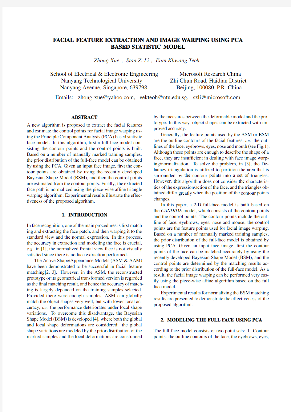
Generally,the feature points used by the ASM or BSM are the outline contours of the facial features,i.e.the out-lines of the face,eyebrows,eyes,nose and mouth(see Fig.1). Although these points are enough to describe the shape of a face,they are insuf?cient in dealing with face image warp-ing/normalization.To solve the problem,in[3],the De-launey triangulation is utilized to partition the area that is surrounded by the contour points into a set of triangles. However,this algorithm does not consider the characteris-tics of the expression/action of the face,and the triangles ob-tained differ greatly when the position of the contour points changes.
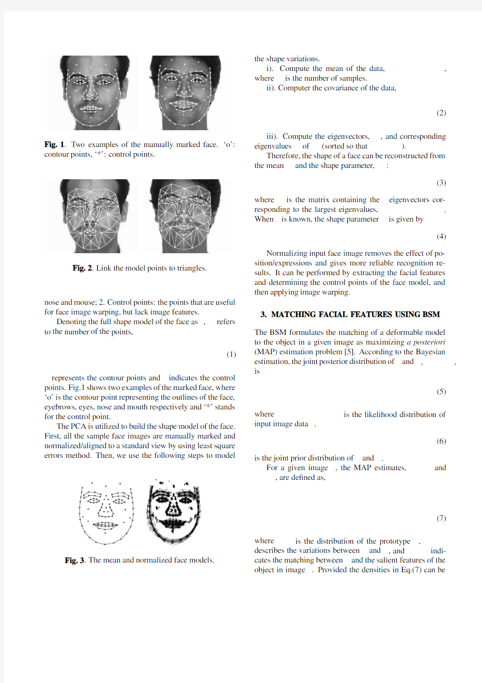
In this paper,a2-D full-face model is built based on the CANDIDE model,which consists of the contour points and the control points.The contour points include the out-line of face,eyebrows,eyes,nose and mouse;the control points are the feature points used for facial image warping. Based on a number of manually marked training samples, the prior distribution of the full-face model is obtained by using PCA.Given an input face image,?rst the contour points of the face can be matched accurately by using the recently developed Bayesian Shape Model(BSM),and the control points are determined by the matching results ac-cording to the prior distribution of the full-face model.As a result,the facial image warping can be performed very eas-ily using the piece-wise af?ne algorithm based on the full face model.
Experimental results for normalizing the BSM matching results are presented to demonstrate the effectiveness of the proposed algorithm.
2.MODELING THE FULL FACE USING PCA The full-face model consists of two point sets:1.Contour points:the outline contours of the face,the eyebrows,eyes,
contour points,‘*’:control
points.
nose and mouse;2.Control points:the points that are useful for face image warping,but lack image features.
Denoting the full shape model of the face as ,refers to the number of the points,
(1)
represents the contour points and indicates the control
points.Fig.1shows two examples of the marked face,where ‘o’is the contour point representing the outlines of the face,eyebrows,eyes,nose and mouth respectively and ‘*’stands for the control point.
The PCA is utilized to build the shape model of the face.First,all the sample face images are manually marked and normalized/aligned to a standard view by using least square errors method.Then,we use the following steps to
model
the shape variations.
i).Compute the mean of the data,,
where is the number of samples.
ii).Computer the covariance of the data,
(2)
iii).Compute the eigenvectors,,and corresponding eigenvalues of (sorted so that ).
Therefore,the shape of a face can be reconstructed from the mean and the shape parameter,:
(3)
where
is the matrix containing the eigenvectors cor-responding to the largest eigenvalues,.
When is known,the shape parameter
is given by
(4)
Normalizing input face image removes the effect of po-sition/expressions and gives more reliable recognition re-sults.It can be performed by extracting the facial features and determining the control points of the face model,and then applying image warping.
3.MATCHING FACIAL FEATURES USING BSM The BSM formulates the matching of a deformable model to the object in a given image as maximizing a posteriori (MAP)estimation problem [5].According to the Bayesian estimation,the joint posterior distribution of and ,,
is
(5)
where
is the likelihood distribution of
input image data .
(6)
is the joint prior distribution of and .
For a given image ,the MAP estimates,and
,are de?ned as,
(7)
where is the distribution of the prototype ,describes the variations between and ,and indi-cates the matching between and the salient features of the object in image .Provided the densities in Eq.(7)can be
modeled as Gibb’s distribution,maximizing the posterior distribution is equivalent to minimizing the corresponding energy function of the contour:
(8) where.
The constraint energy term of the prototype con-tour is caused by the prior distribution,,which can be approximated by and modeled by a single Gaussian distribution[6].
(9)
where is given in Eq.(4).Since is unknown,it is set to.Experiments show that this approximation is accept-able because generally the variations of can represent the variations of the full-face model.Therefore,the constraint energy is denoted as
(10)
The variations of the prototypes contour is limited by the plausible area of the corresponding shape parameters,
(11)
The threshold,,is chosen using the distribution[2].
On the other hand,BSM uses a transformational invari-ant internal energy term,which describes degree of match-ing between the deformable model in the image domain and the prototype in the shape domain.Mathematically, and are related by, where is the transformational matrix,T is a translation vector.The invariant internal energy term is de?ned as(see [7]about the detail of Eq.(14):
(12)
(13)
(14)
The external energy term can be calculated as follows [8].
First,the image is smoothed using Gaus-sian function,,.Sec-ond,the normalized gradient of the smoothed image at each pixel location,is computed:
,and?nally,the external energy is de?ned as:
(15)
is the direction(unit vector)of the gradient, and indicates the normal vector of the contour at point,with and
is the tan-gent vector of contour at point.
4.DETERMINING THE CONTROL POINTS FOR
FACIAL IMAGE W ARPING
Using the BSM facial feature extraction algorithm,the match-ing results of the contour points and,and the pose rela-tionship and(between and)can be obtained.Then, the contour points in the shape domain is calculated by
(16) The algorithm to determine the control points correspond-ing to is to estimate the shape parameter,so that the contour points of the reconstructed model
match closely,and hence the corresponding reconstructed control points can be regarded as the estimate of the con-trol points.The detail algorithm is follows,
i).The estimation problem is to?nd out,so that the re-sult matches in the sense of least square errors.From Eq.(3),can be calculated by
(17) where is a unity matrix and is a zero matrix.Denoting
,,and noting that,,and
are known,the shape parameter can be estimated using
(18) ii).The control points can be calculated through,
(19)
Fig.4.The original (upper row)and the warped (lower row)face images.
iii).The ?nal full-face contour in the shape domain is rep-resented by
and hence its transformed counter-part in the image domain,is
.
Fig.4shows several examples of the warping results us-ing the proposed face model.The upper row is the orig-inal faces,while the bottom row is the warped images of
the upper row correspondingly.For example,the ?rst col-umn of the images illustrates changing the expression to smile,and the second column stops the smile.It can be seen from the ?gure that the face model describes the face well and by image warping,the expressions of face can be removed/changed,which is very useful for face recognition.
5.EXPERIMENTAL RESULTS
The experiments are carried out using the BSM toolkit de-veloped in the Matlab 5.3Environment.Given an input face image,the BSM is utilized to match the contour points of the face model.The matching results are then utilized to estimate the control points of the face model to obtain the extracted full face in the image domain.Finally,an im-age warping algorithm is performed to transfer the extracted face into the mean of the face model in the shape domain.Fig.5presents examples of the experiment results using the proposed algorithm.The left column is the input face im-age,the middle column shows the extracted contour points,and the normalized faces are plotted in the right column.
6.CONCLUSION
In this paper,a full-face model consisting the contour points and the control points is built based on PCA,and an algo-rithm is proposed to estimate the control points from the contour points that are matched by the BSM facial feature extraction algorithm.Then the warping and normalization of the extracted face patch can be performed by using piece-wise af?ne algorithm.Experimental results demonstrate
good
tion/warping results.
performance of the proposed algorithm.
7.REFERENCES
[1]W.Zhao and R.Chellappa,“Sfs based view synthesis for ro-bust face recognition,”in 4th IEEE Conference on Automatic Face and Gesture Recognition,Grenoble,France ,2000,pp.285–292.[2]T.F.Cootes,C.J.Taylor,D.H.Cooper,and J.Graham,“Ac-tive shape models -their training and application,”Computer Vision and Image Understanding ,vol.61,no.1,pp.38–59,1995.[3]T.Cootes,G.J.Edwards,and C.J.Taylor,“Active appearance
models,”in Proceeding of 5th European Conference on Com-puter Vision ,1998,vol.2,pp.484–498.[4]Z.Xue,Stan Z.Li,J.W.Lu,and E.K.Teoh,“Bayesian model
for extracting facial features,”in Sixth International Con-ference on Control,Automation,Robotics &Vision,ICARCV 2000,Dec.,Singapore ,2000.[5]Stan.Z.Li and J.Lu,“Modeling Bayesian estimation for de-formable contours,”in Proceedings of 7th IEEE International Conference on Computer Vision,Kerkyra,Greece.,1999,pp.991–996.[6] B.Moghaddam and A.Pentland,“Probabilistic visual
learninig for object representation,”IEEE Transactions on Pattern Analysis and Machine Intelligence ,vol.19,no.7,pp.696–710,1997.[7]H.H.S.Ip and D.Shen,“An af?ne-invariant active contour
model (AI-Snake)for model-based segmentation,”Image and Vision Computing ,vol.16,no.2,pp.125–146,1998.[8] A.L.Yuille,P.W.Hallinan,and D.S.Cohen,“Feature extrac-tion from faces using deformable templates,”International Journal of Computer Vision ,vol.8,no.2,pp.99–111,1992.
图像处理及识别技术在机器人路径规划中的一种应用 摘要:目前,随着计算机和通讯技术的发展,在智能机器人系统中,环境感知与定位、路径规划和运动控制等功能模块趋向于分布式的解决方案。机器人路径规划问题是智能机器人研究中的重要组成部分,路径规划系统可以分为环境信息的感知与识别、路径规划以及机器人的运动控制三部分,这三部分可以并行执行,提高机器人路径规划系统的稳定性和实时性。在感知环节,视觉处理是关键。本文主要对机器人的路径规划研究基于图像识别技术,研究了图像处理及识别技术在路径规划中是如何应用的,机器人将采集到的环境地图信息发送给计算机终端,计算机对图像进行分析处理与识别,将结果反馈给机器人,并给机器人发送任务信息,机器人根据接收到的信息做出相应的操作。 关键词:图像识别;图像处理;机器人;路径规划 ABSTRACT:At present, with the development of computer and communication technology, each module, such as environment sensing, direction deciding, route planning and movement controlling moduel in the system of intelligent robot, is resolved respectively. Robot path planning is an part of intelligent robot study. The path planning system can be divided into three parts: environmental information perception and recognition, path planning and motion controlling. The three parts can be executed in parallel to improve the stability of the robot path planning system. As for environment sensing, vision Proeessing is key faetor. The robot path planning of this paper is based on image recognition technology. The image processing and recognition technology is studied in the path planning is how to apply, Robots will sent collected environment map information to the computer terminal, then computer analysis and recognize those image information. After that computer will feedback the result to the robot and send the task information. The robot will act according to the received information. Keywords: image recognition,image processing, robot,path planning
中英文资料对照外文翻译 一、英文原文 A NEW CONTENT BASED MEDIAN FILTER ABSTRACT In this paper the hardware implementation of a contentbased median filter suitabl e for real-time impulse noise suppression is presented. The function of the proposed ci rcuitry is adaptive; it detects the existence of impulse noise in an image neighborhood and applies the median filter operator only when necessary. In this way, the blurring o f the imagein process is avoided and the integrity of edge and detail information is pre served. The proposed digital hardware structure is capable of processing gray-scale im ages of 8-bit resolution and is fully pipelined, whereas parallel processing is used to m inimize computational time. The architecturepresented was implemented in FPGA an d it can be used in industrial imaging applications, where fast processing is of the utm ost importance. The typical system clock frequency is 55 MHz. 1. INTRODUCTION Two applications of great importance in the area of image processing are noise filtering and image enhancement [1].These tasks are an essential part of any image pro cessor,whether the final image is utilized for visual interpretation or for automatic an alysis. The aim of noise filtering is to eliminate noise and its effects on the original im age, while corrupting the image as little as possible. To this end, nonlinear techniques (like the median and, in general, order statistics filters) have been found to provide mo re satisfactory results in comparison to linear methods. Impulse noise exists in many p ractical applications and can be generated by various sources, including a number of man made phenomena, such as unprotected switches, industrial machines and car ign ition systems. Images are often corrupted by impulse noise due to a noisy sensor or ch annel transmission errors. The most common method used for impulse noise suppressi on n forgray-scale and color images is the median filter (MF) [2].The basic drawback o f the application of the MF is the blurringof the image in process. In the general case,t he filter is applied uniformly across an image, modifying pixels that arenot contamina ted by noise. In this way, the effective elimination of impulse noise is often at the exp ense of an overalldegradation of the image and blurred or distorted features[3].In this paper an intelligent hardware structure of a content based median filter (CBMF) suita ble for impulse noise suppression is presented. The function of the proposed circuit is to detect the existence of noise in the image window and apply the corresponding MF
一般来说,图像识别就是按照图像地外貌特征,把图像进行分类.图像识别地研究首先要考虑地当然是图像地预处理,随着小波变换地发展,其已经成为图像识别中非常重要地图像预处理方案,小波变换在信号分析识别领域得到了广泛应用. 现流行地算法主要还有有神经网络算法和霍夫变换.神经网络地方法,利用神经网络进行图像地分类,而且可以跟其他地技术相互融合.个人收集整理勿做商业用途 一神经网络算法 人工神经网络(,简写为)也简称为神经网络()或称作连接模型(),它是一种模范动物神经网络行为特征,进行分布式并行信息处理地算法数学模型.这种网络依靠系统地复杂程度,通过调整内部大量节点之间相互连接地关系,从而达到处理信息地目地.个人收集整理勿做商业用途 在神经网络理论地基础上形成了神经网络算法,其基本地原理就是利用神经网络地学习和记忆功能,让神经网络学习各个模式识别中大量地训练样本,用以记住各个模式类别中地样本特征,然后在识别待识样本时,神经网络回忆起之前记住地各个模式类别地特征并将他们逐个于样本特征比较,从而确定样本所属地模式类别.他不需要给出有关模式地经验知识和判别函数,通过自身地学习机制形成决策区域,网络地特性由拓扑结构神经元特性决定,利用状态信息对不同状态地信息逐一训练获得某种映射,但该方法过分依赖特征向量地选取.许多神经网络都可用于数字识别,如多层神经网络用于数字识别:为尽可能全面描述数字图像地特征,从很多不同地角度抽取相应地特征,如结构特征、统计特征,对单一识别网络,其输入向量地维数往往又不能过高.但如果所选取地特征去抽取向量地各分量不具备足够地代表性,将很难取得较好地识别效果.因此神经网络地设计是识别地关键.个人收集整理勿做商业用途 神经网络在图像识别地应用跟图像分割一样,可以分为两大类: 第一类是基于像素数据地神经网络算法,基于像素地神经网络算法是用高维地原始图像数据作为神经网络训练样本.目前有很多神经网络算法是基于像素进行图像分割地,神经网络,前向反馈自适应神经网络,其他还有模糊神经网络、神经网络、神经网络、细胞神经网络等.个人收集整理勿做商业用途 第二类是基于特征数据地神经网络算法.此类算法中,神经网络是作为特征聚类器,有很多神经网络被研究人员运用,如神经网络、模糊神经网络、神经网络、自适应神经网络、细胞神经网络和神经网络.个人收集整理勿做商业用途 例如神经网络地方法在人脸识别上比其他类别地方法有独到地优势,它具有自学习、自适应能力,特别是它地自学能力在模式识别方面表现尤为突出.神经网络方法可以通过学习地过程来获得其他方法难以实现地关于人脸识别规律和规则地隐性表达.但该方法可能存在训练时间长、收敛速度慢地缺点.个人收集整理勿做商业用途 二小波变换 小波理论兴起于上世纪年代中期,并迅速发展成为数学、物理、天文、生物多个学科地重要分析工具之一;其具有良好地时、频局域分析能力,对一维有界变差函数类地“最优”逼近性能,多分辨分析概念地引入以及快速算法地存在,是小波理论迅猛发展地重要原因.小波分析地巨大成功尤其表现在信号处理、图像压缩等应用领域.小波变换是一种非常优秀地、具有较强时、频局部分析功能地非平稳信号分析方法,近年来已在应用数序和信号处理有很大地发展,并取得了较好地应用效果.在频域里提取信号里地相关信息,通过伸缩和平移算法,对信号进行多尺度分类和分析,达到高频处时间细分、低频处频率细分、适应时频信号分解地要求.小波变换在图像识别地应用,包括图形去噪、图像增强、图像融合、图像压缩、图像分解和图像边缘检测等.小波变换在生物特征识别方面(例如掌纹特征提取和识别)同样得到了成功应用,部分研究结果表明在生物特征识别方面效果优于、、傅里叶变换等方
智能图像分析系统 解 决 方 案
北京恒泰同兴科技有限公司北京恒泰同兴科技有限公司是注册在中关村科技园区的高科技企业,成立于2004年,具有稳定的研发、生产、销售、服务队伍。恒泰同兴坚持自主开发之路,以“创造最大核心价值”为目标,以数字化、网络化、智能化为发展方向,专业从事图像智能识别、分析判断及自动处理产业化研究;公司研发的智能图像处理系统,与传统监控系统配合,为视频监控系统提供具有智能图像识别分析和告警的功能。可实现周界警戒与入侵检测、警戒线穿越检测、重要物品看护、遗留/遗弃物品检测、人体行为识别、道路交通检测等功能,可在各种恶劣气候、环境条件下进行目标识别和检测,避免了人工监控存在的易疲劳、易疏忽、反应速度慢、人工费用高等诸多不足,为客户提供了最佳安全监控系统解决方案。同时公司成功地开发大型行业联网解决方案,并有大量的实际案例,在视频监控行业积累了丰富的经验,智能监控和联网平台为用户提供了全方位的解决方案。公司本着诚实守信的经营之道,整合各种先进的技术资源,为客户定制最先进的行业解决方案,与各界用户一道,共同推进图像视频监控数字化、智能化和网络化进程。 恒泰同兴:持之以恒、稳如泰山 诚实、守信、专业、共赢
一、智能产品简介 智能视频分析系统是由位于前端或后端视频分析服务器,对监控摄像机所拍摄的视频图像进行分析,能将影像中的人、车或者物体的状态从任何背景中分离出来,加以辨认、分析与追踪。比对出所追踪对象的行为模式与预设的诸项安全规则,若发现违规之处,立刻进行报警通知,同时由使用平台进行信息记录或显示。 二、智能分析的功能 目前,智能视频分析系统在视频监控方向的应用主要在对运动目标的识别、分类和追踪。可以设置的规则、功能为以下几种:1、绊线检测 针对人、车通过特定运动方向绊线的监控;其应用如:警戒线、单向闸门流向、 栅栏攀爬…等;支持警戒区内多个目标同时告警、显示、报警图片抓拍、而且有 声音提示
实验一图像处理基本操作 一、 实验目的 1、熟悉并掌握在MATLAB中进行图像类型转换及图像处理的基本操作。 2、熟练掌握图像处理中的常用数学变换。 二、实验设备 1、计算机1台 2、MATLAB软件1套 3、实验图片 三、实验原理 1、数字图像的表示和类别 一幅图像可以被定义为一个二维函数f(x,y),其中x和y是空间(平面)坐标,f在坐标(x,y)处的幅度称为图像在该点的亮度。灰度是用来表示黑白图像亮度的一个术语,而彩色图像是由若干个二维图像组合形成的。例如,在RGB彩色系统中,一幅彩色图像是由三幅独立的分量图像(红、绿、蓝)组成的。因此,许多为黑白图像处理开发的技术也适用于彩色图像处理,方法是分别处理三幅独立的分量图像即可。 图像关于x和y坐标以及幅度连续。要将这样的一幅图像转化为数字形式,就要求数字化坐标和幅度。将坐标值数字化称为取样,将幅度数字化称为量化。采样和量化的过程如图1所示。因此,当f的x、y分量和幅度都是有限且离散的量时,称该图像为数字图像。 作为MATLAB基本数据类型的数组十分适于表达图像,矩阵的元素和图像的像素之间有着十分自然的对应关系。 图1 图像的采样和量化 图1 采样和量化的过程 根据图像数据矩阵解释方法的不同,MATLAB把其处理为4类: ?亮度图像(Intensity images) ?二值图像(Binary images) ?索引图像(Indexed images) ? RGB图像(RGB images) (1) 亮度图像 一幅亮度图像是一个数据矩阵,其归一化的取值表示亮度。若亮度图像的像素都是uint8类型或uint16类型,则它们的整数值范围分别是[0,255]和[0,65536]。若图像是double 类型,则像素取值就是浮点数。规定双精度double型归一化亮度图像的取值范围是[0 1]。 (2) 二值图像 一幅二值图像是一个取值只有0和1的逻辑数组。而一幅取值只包含0和1的uint8
附录一英文原文 Illustrator software and Photoshop software difference Photoshop and Illustrator is by Adobe product of our company, but as everyone more familiar Photoshop software, set scanning images, editing modification, image production, advertising creative, image input and output in one of the image processing software, favored by the vast number of graphic design personnel and computer art lovers alike. Photoshop expertise in image processing, and not graphics creation. Its application field, also very extensive, images, graphics, text, video, publishing various aspects have involved. Look from the function, Photoshop can be divided into image editing, image synthesis, school tonal color and special effects production parts. Image editing is image processing based on the image, can do all kinds of transform such as amplifier, reducing, rotation, lean, mirror, clairvoyant, etc. Also can copy, remove stain, repair damaged image, to modify etc. This in wedding photography, portrait processing production is very useful, and remove the part of the portrait, not satisfied with beautification processing, get let a person very satisfactory results. Image synthesis is will a few image through layer operation, tools application of intact, transmit definite synthesis of meaning images, which is a sure way of fine arts design. Photoshop provide drawing tools let foreign image and creative good fusion, the synthesis of possible make the image is perfect. School colour in photoshop with power is one of the functions of deep, the image can be quickly on the color rendition, color slants adjustment and correction, also can be in different colors to switch to meet in different areas such as web image design, printing and multimedia application. Special effects production in photoshop mainly by filter, passage of comprehensive application tools and finish. Including image effects of creative and special effects words such as paintings, making relief, gypsum paintings, drawings, etc commonly used traditional arts skills can be completed by photoshop effects. And all sorts of effects of production are
智能视频分析系统
目录 一、项目背景及建设目标 (3) 1.1 项目背景 (3) 1.2 技术优势 (4) 二、厂区智能视频分析整体设计方案 (5) 2.1传统对射系统与智能视频分析系统比较 (5) 2.2厂房周界入侵报警系统 (6) 2.2.1 周界入侵检测 (7) 2.2.2 周界警戒线警戒区预警 (8) 2.3厂房仓库物资看护 (8) 2.3.1 可疑人员接近仓库提醒 (8) 2.3.2 仓库物品看护 (9) 2.3.3 夜间停车场、厂区内部、附近可疑逗留检测 (9) 2.4夜间厂区办公楼内可疑人员检测 (10) 2.5生产车间危险区域或者夜间下班后人员检测 (10) 2.6系统拓扑结构 (11)
一、项目背景及建设目标 1.1 项目背景 慧视科技智能视频分析系统是以软件的形式实现智能视频分析功能,拥有自主的软件知识产权,可满足各行业的需要,也满足各厂家设备的接入,同时可以与各种监控平台进行二次对接。传统报警设备的误报多漏报多操作复杂不直观已经成为行业共识,且传统的视频监控系统数量庞大画面单一,工作人员很难从视频中发现问题,往往更多用于事后取证,智能图像分析通过图像中目标的识别和规则运用来进行预警,报警速度快且精确度高,可辅助工作人员从繁琐重复的工作中解放出来,真正体现科技为人服务的理念。 国内现有厂房的视频监控系统主要由摄像机、光缆、矩阵、硬盘录像机和电视墙等组成。由于视频监控图像数量大,内容枯燥,现有系统即使配备值班人员,在大多数情况下仍处于无人观看的状态下。当犯罪事件发生时,从硬盘录像机中调取录像回放、取证变成系统主要的价值之一。即使值班人员在岗,由于人的生理特点,不可能长时间有效观察多路图像,很可能造成遗漏可疑事件,对安全形式产生错误判断。 智能视频监控技术可以理解为用计算机来帮助值班人员"看"监控录像。现代计算机的高可靠性可以提供24小时不间断地保护。从根本上杜绝由于人员疲劳造成的遗漏问题。同时也可以防止出现监控人员内外勾结的可能性。
实训三:图像频域处理基本操作 一:实验的目的 1:掌握基本的离散傅里叶变换操作,熟悉命令fftn, fftshift,ifftn。 2:对图像text.png进行图像特征识别操作。 二:实验指导: 1.通过MATLAB的Help文档,学习Image Processing Toolbox中关于图像变换的内容。 2.通过MATLAB的Help文档,查询命令fftn, fftshift,ifftn的用法。 3. 用MATLAB生成一个矩形连续函数并得到它的傅里叶变换的频谱。
4.对图像text.png中的字母a完成特征识别操作。
一 bw = imread('text.png'); a = bw(32:45,88:98); imview(bw); imshow(bw); figure, imshow(a); C = real(ifft2(fft2(bw) .* fft2(rot90(a,2),256,256))); figure, imshow(C,[]) max(C(:)) thresh = 60; figure, imshow(C > thresh) ans = 68
N=100 f=zeros(500,500); f(60:180,30:400)=1; subplot(221),imshow(f) subplot(221),imshow(f,'notruesize') F1=fft2(f,N,N),
F1=fft2(f,N,N), F2=fftshift(abs(F1)); F3=abs(log(1+F2)); subplot(222), imshow(F3,[]) imshow(F3,[]); f1=imrotate(f,45,'bicubic') subplot(223),imshow(f1); F21=fft2(f1,N,N); F22=abs((log(1+F22)); F22=abs((log(1+F21))); F23=abs(log(1+F22)); subplot(224), imshow(F23,[])
Algebraic operation 代数运算一种图像处理运算,包括两幅图像对应像素的和、差、积、商。 Aliasing 走样(混叠)当图像像素间距和图像细节相比太大时产生的一种人工痕迹。Arc 弧图的一部分;表示一曲线一段的相连的像素集合。 Binary image 二值图像只有两级灰度的数字图像(通常为0和1,黑和白) Blur 模糊由于散焦、低通滤波、摄像机运动等引起的图像清晰度的下降。 Border 边框一副图像的首、末行或列。 Boundary chain code 边界链码定义一个物体边界的方向序列。 Boundary pixel 边界像素至少和一个背景像素相邻接的内部像素(比较:外部像素、内部像素) Boundary tracking 边界跟踪一种图像分割技术,通过沿弧从一个像素顺序探索到下一个像素将弧检测出。 Brightness 亮度和图像一个点相关的值,表示从该点的物体发射或放射的光的量。 Change detection 变化检测通过相减等操作将两幅匹准图像的像素加以比较从而检测出其中物体差别的技术。 Class 类见模或类 Closed curve 封闭曲线一条首尾点处于同一位置的曲线。 Cluster 聚类、集群在空间(如在特征空间)中位置接近的点的集合。 Cluster analysis 聚类分析在空间中对聚类的检测,度量和描述。 Concave 凹的物体是凹的是指至少存在两个物体内部的点,其连线不能完全包含在物体内部(反义词为凸) Connected 连通的 Contour encoding 轮廓编码对具有均匀灰度的区域,只将其边界进行编码的一种图像压缩技术。 Contrast 对比度物体平均亮度(或灰度)与其周围背景的差别程度 Contrast stretch 对比度扩展一种线性的灰度变换 Convex 凸的物体是凸的是指连接物体内部任意两点的直线均落在物体内部。Convolution 卷积一种将两个函数组合成第三个函数的运算,卷积刻画了线性移不变系统的运算。 Corrvolution kernel 卷积核1,用于数字图像卷积滤波的二维数字阵列,2,与图像或信号卷积的函数。 Curve 曲线1,空间的一条连续路径,2 表示一路径的像素集合(见弧、封闭曲线)。 Deblurring 去模糊1一种降低图像模糊,锐化图像细节的运算。2 消除或降低图像的模糊,通常是图像复原或重构的一个步骤。 Decision rule 决策规则在模式识别中,用以将图像中物体赋以一定量的规则或算法,这种赋值是以对物体特征度量为基础的。 Digital image 数字图像 1 表示景物图像的整数阵列,2 一个二维或更高维的采样并量化的函数,它由相同维数的连续图像产生,3 在矩形(或其他)网络上采样一连续函数,并才采样点上将值量化后的阵列。 Digital image processing 数字图像处理对图像的数字化处理;由计算机对图片信息进
图像处理的基本步骤 针对不同的目的,图像处理的方法不经相同。大体包括图像预处理和图像识别两大模块。 一、图像预处理: 结合识别复杂环境下的成熟黄瓜进行阐述,具体步骤如下: · 图像预处理阶段的流程图 对以上的图像流程进行详细的补充说明: 图像预处理的概念: 将每一个文字图像分检出来交给识别模块识别,这一过程称为图像预处理。 图像装换和图像分割以及区域形态学处理都是属于图像处理的基本内容之一。 图像转换:方法:对原图像进行灰度化处理生成灰度矩阵——降低运算速度(有具体的公式和方程),中值滤波去噪声——去除色彩和光照的影响等等。 图像分割:传统方法:基于阈值分割、基于梯度分割、基于边缘检测分割和基于区域图像割等方法。脉冲耦合神经网络 (PCNN)是针对复杂环境下 图像采集 图像采集中注意采集的方法、工具进行介绍。目的是怎样获取有代表性的样本。(包括天气、相机的位置等) 对采集的图像进行特征分析 目标的颜色和周围环境的颜色是否存在干涉的问题、平整度影响相机的拍摄效果、形状 图像转换 图像分割 区域形态学处理
的有效分割方法,分割的时候如果将一个数字图像输入PCNN,则能基于空间邻近性和亮度相似性将图像像素分组,在基于窗口的图像处理应用中具有很好的性能。 区域形态学处理:对PCNN分割结果后还存在噪声的情况下,对剩余的噪声进行分析,归类属于哪一种噪声。是孤立噪声还是黏连噪声。采用区域面积统计法可以消除孤立噪声。对于黏连噪声,可以采用先腐蚀切断黏连部分,再膨胀复原目标对象,在进行面积阙值去噪,通过前景空洞填充目标,最后通过形态学运算,二值图像形成众多独立的区域,进行各连通区域标识,利于区域几何特征的提取。 二、图像识别: 针对预处理图像提取 目标特征 建立LS SVM分类器 得到结果 图像识别流程图 提取目标特征:目标特征就是的研究对象的典型特点,可以包括几何特征和纹理特征。 对于几何特征采用的方法:采用LS-SVM支持向量机对几何特征参数进行处理,通过分析各个参数的分布区间来将目标和周围背景区分开,找出其中具有能区分功能的决定性的几何特征参数。 纹理特征方法:纹理特征中的几个参数可以作为最小二乘支持向量机的辅助特征参数,提高模型的精准度。 最小二乘支持向量机介绍:首先选择非线性映射将样本从原空间映射到特征空间,以解决原空间中线性不可分问题,在此高维空间中把最优决策问题转化为等式约束条件,构造最优决策函数,并引入拉格朗日乘子求解最优化问题,对各个变量求偏微分。 LS SVM分类器:对于p种特征选择q个图像连通区域,作为训练样本。依
i=imread('D:\00001.jpg'); >> j=rgb2gray(i); >> warning off >> imshow(j); >> u=edge(j,'roberts'); >> v=edge(j,'sobel'); >> w=edge(j,'canny'); >> x=edge(j,'prewitt'); >> y=edge(j,'log'); >> h=fspecial('gaussian',5); >> z=edge(j,'zerocross',[],h); >> subplot(2,4,1),imshow(j) >> subplot(2,4,2),imshow(u) >> subplot(2,4,3),imshow(v) >> subplot(2,4,4),imshow(w) >> subplot(2,4,5),imshow(x) >> subplot(2,4,6),imshow(y) >> subplot(2,4,7),imshow(z)
>> %phi:地理纬度lambda:地理经度delta:赤纬omega:时角lx 影子长,ly 杆长 >> data=xlsread('D:\附件1-3.xls','附件1'); >> X = data(:,2); >> Y = data(:,3); >> [x,y]=meshgrid(X,Y); %生成计算网格 >> fxy = sqrt(x.^2+y.^2); >> %[Dx,Dy] = gradient(fxy); >> Dx = x./fxy; >> Dy = y./fxy; >> quiver(X,Y,Dx,Dy); %用矢量绘图函数绘出梯度矢量大小分布>> hold on >> contour(X,Y,fxy); %与梯度值对应,绘出原函数的等值线图
使用ENVI进行图像处理 主要介绍利用envi进行图像处理的基本操作,主要分为图像合成、图像裁减、图像校正、图像镶嵌、图像融合、图像增强。 分辨率:空间分辨率、波谱分辨率、时间分辨率、辐射分辨率。咱们平时所说的分辨率是指?怎么理解? 1、图像合成 对于多光谱影像,当我们要得到彩色影像时,需要进行图像合成,产生一个与自然界颜色一致的真彩色(假彩色)图像。 对于不同类型的影像需要不同的波段进行合成,如中巴CCD影像共5个波段,一般选择2、4、3进行合成。(为什么不选择其他波段?重影/不是真彩色)。SOPT5影像共7个波段,一般选择7、4、3三个波段。 操作过程以中巴资源卫星影像为例 中巴资源卫星影像共有五个波段,选择2、4、3三个波段对R、G、B赋值进行赋值。 在ENVI中的操作如下: (1)file→open image file→打开2、3、4三个波段,选择RGB,分别将2、4、3赋予RGB。(2)在#1窗口file---〉save image as-→image file。 (3)在主菜单中将合成的文件存为tiff格式(file-→save file as-→tiff/geotiff) 即可得到我们需要的彩色图像。 2、图像裁减 有时如果处理较大的图像比较困难,需要我们进行裁减,以方便处理。如在上海出差时使用的P6、SOPT5,图幅太大不能直接校正需要裁减。 裁减图像,首先制作AOI文件再根据AOI进行裁减。一般分为两种:指定范围裁减、不指定范围裁减。 不指定范围裁减在ENVI中的操作如下: (1)首先将感兴趣区存为AOI文件 file→open image file打开原图像→选择IMAGE窗口菜单overlay→region of interesting 选择划定感兴趣区的窗口如scroll,从ROI_Type菜单选择ROI的类型如Rectangle,在窗口中选出需要选择的区域。在ROI窗口file→Save ROIs将感兴趣区存为ROI文件。
北京揽宇方圆信息技术有限公司 遥感卫星图像处理方法 随着遥感技术的快速发展,获得了大量的遥感影像数据,如何从这些影像中提取人们感兴趣的对象已成为人们越来越关注的问题。但是传统的方法不能满足人们已有获取手段的需要,另外GIS的快速发展为人们提供了强大的地理数据管理平台,GIS数据库包括了大量空间数据和属性数据,以及未被人们发现的存在于这些数据中的知识。将GIS技术引入遥感图像的分类过程,用来辅助进行遥感图像分类,可进一步提高了图像处理的精度和效率。如何从GIS数据库中挖掘这些数据并加以充分利用是人们最关心的问题。GIS支持下的遥感图像分析特别强调RS和GIS的集成,引进空间数据挖掘和知识发现(SDM&KDD)技术,支持遥感影像的分类,达到较好的结果,专家系统表明了该方法是高效的手段。 遥感图像的边缘特征提取观察一幅图像首先感受到的是图像的总体边缘特征,它是构成图像形状的基本要素,是图像性质的重要表现形式之一,是图像特征的重要组成部分。提取和检测边缘特征是图像特征提取的重要一环,也是解决图像处理中许多复杂问题的一条重要的途径。遥感图像的边缘特征提取是对遥感图像上的明显地物边缘特征进行提取与识别的处理过程。目前解决图像特征检测/定位问题的技术还不是很完善,从图像结构的观点来看,主要是要解决三个问题:①要找出重要的图像灰度特征;②要抑制不必要的细节和噪声;③要保证定位精度图。遥感图像的边缘特征提取的算子很多,最常用的算子如Sobel算子、Log算子、Canny算子等。 1)图像精校正 由于卫星成像时受采样角度、成像高度及卫星姿态等客观因素的影响,造成原始图像非线性变形,必须经过几何精校正,才能满足工作精度要求一般采用几何模型配合常规控制点法对进行几何校正。 在校正时利用地面控制点(GCP),通过坐标转换函数,把各控制点从地理空间投影到图像空间上去。几何校正的精度直接取决于地面控制点选取的精度、分布和数量。因此,地面控制点的选择必须满足一定的条件,即:地面控制点应当均匀地分布在图像内;地面控制点应当在图像上有明显的、精确的定位识别标志,如公路、铁路交叉点、河流叉口、农田界线等,以保证空间配准的精度;地面控制点要有一定的数量保证。地面控制点选好后,再选择不同的校正算子和插值法进行计算,同时,还对地面控制点(GCPS)进行误差分析,使得其精度满足要求为止。最后将校正好的图像与地形图进行对比,考察校正效果。 2)波段组合及融合 对卫星数据的全色及多光谱波段进行融合。包括选取最佳波段,从多种分辨率融合方法中选取最佳方法进行全色波段和多光谱波段融合,使得图像既有高的空间分辨率和纹理特性,又有丰富的光谱信息,从而达到影像地图信息丰富、视觉效果好、质量高的目的。 3)图像镶嵌
智能视频分析系统解决方案 1.1 系统概述 智能视频(Intelligent Video)技术源自计算机视觉(Computer Vision)与人工智能(Artificial Intelligent)的研究,其发展目标是在图像与事件描述之间建立一种映射关系,使计算机从纷繁的视频图像中分辩、识别出关键目标物体。这一研究应用于安防视频监控系统,将能借助计算机强大的数据处理能力过滤掉图像中无用的或干扰信息,自动分析、抽取视频源中的关键有用信息,从而使传统监控系统中的摄像机成为人的眼睛,使“智能视频分析”计算机成为人的大脑,并具有更为“聪明”的学习思考方式。这一根本性的改变,可极大地发挥与拓展视频监控系统的作用与能力,使监控系统具有更高的智能化,大幅度节省资源与人员配置,同时必将全面提升安全防范工作的效率。因此,智能视频监控不仅仅是一种图像数字化监控分析技术,而是代表着一种更为高端的数字视频网络监控应用。 智能视频分析包含视频诊断、视频分析和视频增强等,它们各自又包含了大量的功能算法,比如清晰度检测、视频干扰检测、亮度色度检测、PTZ(云台)控制功能检测,以及视频丢失、镜头遮挡、镜头喷涂、非正常抖动等检测都属于视频诊断内容,而视频分析算法则包含区域入侵、绊线检测、遗留遗失检测、方向检测、人群计数、徘徊检测、流量统计、区域稠密度统计、人脸识别、车牌识别、烟火烟雾检测、自动 PTZ 跟踪等功能,视频图像增强则包括稳像、去雾、去噪、全景拼接等算法。由此组合衍生出的算法种类又有很多,应用方式也千变万化,所以智能视频分析的应用范围很广。 在以往的视频监控系统中,操作人员盯着屏幕电视墙超过 10 分钟后将漏掉90%的视频信息,而使视频监控工作失去意义。随着社会发展,视频监控被越来越广泛地应用到各行各业中,摄像机数量越来越庞大,这给传统的视频监控带来严峻的挑战。针对行业发展推出智能视频分析系统,主要解决以下问题:一个是将安防操作人员从繁杂而枯燥的“盯屏幕”任务解脱出来,由机器来完成分析识别工作;另外一个是为在海量的视频数据中快速搜索到想要找的的图象。 1.2 系统组成 智能视频分析系统以数字化、网络化视频监控为基础,用户可以设置某些特定的规则,系统识别不同的物体,同时识别目标行为是否符合这些规则,一旦发现监控画面中的异常情况,系统能够以最快和最佳的方式发出警报并提供有用信息,从而能够更加有效的协助安全人员处理危机,最大限度的降低误报和漏报现象。智能视频分析是在传统的监控系统中,加入智能视频技术,在整个系统中,系统分布图如下:
图像处理基本操作 姓名:王泗凯学号:2012045043 日期:2014.3.10 1.实验目的和内容 为了得到我们想得到的图像效果以及为图像的后续处理做好准备,我们需要对原图像进行一些基本处理操作,以下是对原图像进行一些基本处理的内容和具体步骤。 1.1.设置ENVI 打开ENVI在File下的Preferences里面就是ENVI的基本设置 图1.1-1:设置绘图选项图1.1-2:设置默认显示参数
图1.1-3:设置页面单位和内存分配 图1.1-4:ENVI 系统设置窗口 1.2.打开图像,显示单波段图像、显示彩色图像 打开图像:File -> Open Image File 选择7个单波段图像打开 在窗口中选择Gray Scale ,然后选择想要打开的波段,例如打开第四波段,得到下图所示单波段图像;在窗口中选择RGB Color ,然后进行波段组合,若显示真彩色图像则选择3,2,1三个波段,此处打开真彩色图像,结果如图。 图1.2-1:单波段图像(波段4) 图1.2-2:RGB 合成显示(3,2,1) 1.3.窗口连接 先在Display #1中打开一幅图像(如图1.2-1),再新建一个窗口Display #2打开另一图像(如图1.2-2),在Display #1内右击选择Link Display 得到如图1.3-1所示窗口,即可连接Display #1和Display #2,连接后如图1.3-2。
图1.3-1图像窗口连接 图1.3-2图像连接后显示 1.4.图像格式转换(自行定义转入转出格式) 点击Display #1窗口上的file中的Save Image As,然后选择Image File弹出图1.4-1所示窗口,在Output File Type中即可选择图像要转换成的格式。