Development of a walking machine: mechanical
design and control problems
Teresa Zielinska *, John Heng
Abstract
This paper describes: a novel design of the leg drive mechanism, hardware architecture and the leg control method for a walking machine being developed to study various walking gait strategies. The leg mechanism employs an inverse differential gear drive system providing large
leg lift and swing sweep angle about a common pivotal point while being driven collectively by
a pair of motors. The development platform consists of a pair of legs mounted adjacently to
each other on a linear slide. A three-axis piezo transducer is mounted on the feet to measure the various vector forces in the legs during the support phase. The force sensing results are
presented and discussed. Currently one small four-legged prototype and one hexapod are used for the tests of different gait patterns. _ 2002 Elsevier Science Ltd. All rights reserved.
Keywords: Walking machines; Mechanical design; Control system design; Force sensing
1. Introduction
In comparison with the industrial manipulators, the task of building an adaptable, autonomous walking machine is more difficult. Walking machines have more
active degrees of freedom (DOF) than industrial robots. To enlarge the work-space of the leg-end, and thus enhance the machine’s ability to adapt to the terrain, each leg should have at least three DOF, which results in a total of 12 DOF for a quadruped or 18 DOF for a hexapod. All those joints must be controlled adequately in real time. This also means that the hardware and software systems must meet more critical requirements than those formulated for industrial robot controllers. Moreover, fully
autonomous vehicles use only on-board controllers and so those controllers have to be miniaturized to an utmost extent. There is no such requirement in the case of nonmobile
controllers of manipulators. Theoretical problems that must be solved are
numerous. From an overview of the publications concerning the subject of multilegged walking machines it can be noticed that the main attention is paid to:
? general (technical) description of prototypes, e.g., [1],
? methods of free gait planning, e.g., [2,3],
? problems of gait synthesis using dynamical or quasi-dynamical modelling, (e.g., force distribution problems) – [4–7],
? the problems of motion optimization – [8,9],
? the philosophy of control systems functional decomposition and mechanisms of machines’ adaptive behavior – [10,11].
The description of control software component is lacking. Such a description
is necessary in the systematic development of walking machines, which should be treated as mechatronic systems.
Mechanical structure of a walking machine should not only imitate the leg structure of living creatures (e.g., insects, spiders), but should also take into account the actuating systems properties (e.g., size, weight and power of the motors) and constraints
(e.g., size of the body and the leg work-space).
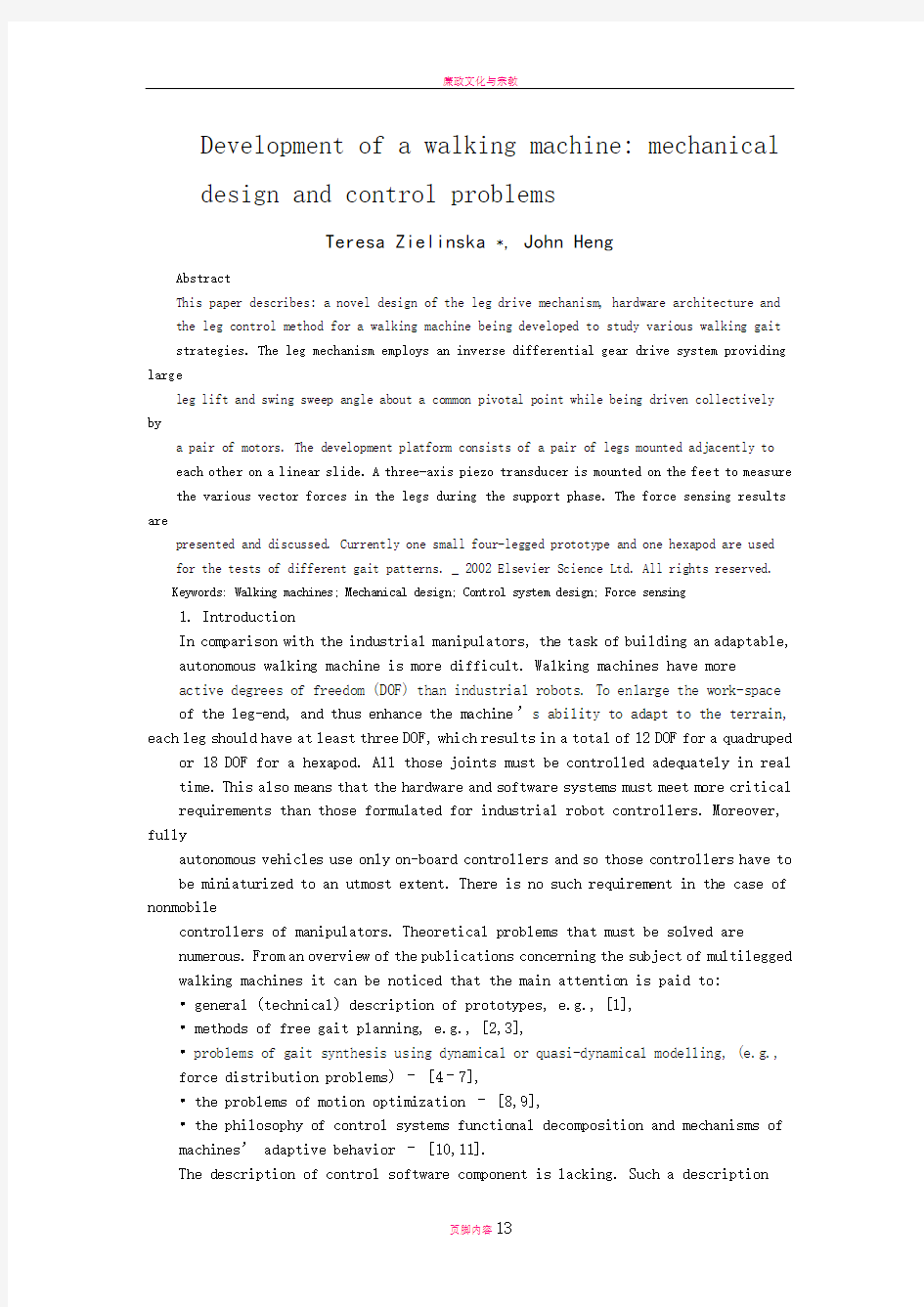
Fig. 1. LAVA using the
multipurpose leg being
developed at RRC (Robotics
Research Centre – Nanyang
Technological
University, Singapore).
In this paper, we
are presenting the
mechanical structure
of a multilegged
machine
and we are giving a
brief description of joint, leg and gait levels of the control
system.
2. Mechanical design
2.1. Mechanical problems
The need for a general solution to the problem of robot legs design, that can be used either by two-, four- or six-legged vehicles, is clear. However the ability to meet
this need has been hampered by the lack of adequate joint mechanisms and controls.
Joint technology is a key problem in the development of such vehicles, because hip and ankle joints require, at a minimum, pitch and yaw motion about a common
center with remote location of actuation sources analogous to our muscles and joints.
The lack of simple, compact, cost-effective and reliable actuator packages has also been a major stumbling block in current designs. Ineffective joint design leads to unwieldy vehicles that compensate for the instability of their simple joints by means of additional legs.
2.2. Unique differential leg mechanism
The general structure of a walking machine legged autonomous vehicular agent (LAVA) [12,13] is shown in Fig. 1. The thigh section employs a differential gear drive
system to achieve both leg swing and leg lift functions (Fig. 2). This drive system offers two distinct features that are superior to conventional leg design. Firstly, leg
lift and leg swing functions operate from a common geometrical pivot point. This feature will prove beneficial when performing workspace and kinematic modeling.
Secondly during leg swing and leg lift motions, both motors are constantly working together to achieve the desired motion. No motor is left idle and so is not carried around as a dead weight, when only one particular leg motion is in use. The advantage would be that two smaller lighter motors can be utilized which can be
combined to provide a cooperative effort instead of the conventional independent motor drive design. The result would provide savings in power consumption, weight penalty and size constraints. Other power-saving features include using worm gears at a particular gear ratio to drive the various appendages. This provides a self-lock feature thus removing the need to keep the motors continuously powered when
holding the walking machine at a particular orientation. To provide maximum foot placement flexibility with precise turning functions, full three DOF were incorporated
into each leg.
2.3. Fully invertable walking machine platform with amphibious adaptability
The large leg lift and swing angle complements the symmetrical leg design, which enables the walking machine to be invertable. This feature is seen as being essential,
Fig. 2. The differential gear drive system
if the walking machine is to operate within the surf zone of a seashore. The absence of awkwardly exposed mechanical drive systems allows the walking machine to be economically ‘‘water isolated’’ and hence obtains amphibious capability. The walking
machine can be configured to walk on the sea bed or spread its limbs to increase buoyancy and hence swim on the surface (Fig. 3).
2.4. Convertible to insect/mammalian configuration with segmentable leg pair
The wide leg lift and swing capability allow the modular leg to be adapted for use in either an insect or mammalian leg configuration (Fig. 4). Utilizing the leg in
mammalian configuration requires only a small adjustment to the leg geometry. The added benefit of having a wide leg lift and swing capability is that the front two legs
can be adapted to perform probing or pick and place functions (Fig. 5). The modular
Fig. 3. The walking machine in swimming mode.
Fig. 4. Configuration of LAVA’s legs: (a) insect leg configuration; (b) mammalian leg configuration.
leg can be adapted to a four- or six-legged vehicle or employed in an omnidirectional hexapod configuration.
2.5. Conclusion
The modular approach followed in the leg development offers several additional
benefits. The thigh and lower leg length can be adjusted quickly to assume different leg length requirements. There is free space in the central column of the leg to accommodate
various sensors, data and power cables. The current implementation of
the leg design can accommodate two different gear ratios for differential gear drive units. If an increase in drive motor power is required in the future, only minor modifications are required to accommodate the bigger motors. Similarly, leg supporting
beams can economically be resized by changing geometrically simple components.
Finally, with a large leg lift and swing angle the walking machine can be
manipulated in a ‘‘prone’’ mode to operate in restrictive spaces or be neatly folded
for easy storage or deployment (Fig. 6). The leg servo drive actuator system is designed
around a modified differential gear system thus allowing large leg lift and
swing motions to be achieved about the same pivotal point thus providing simpler leg geometry than conventional leg designs.
Fig. 5. Pick and place option.
3. Control system
3.1. Functional decomposition
The functional structure of the control software was decomposed into hierarchically related levels (Fig. 7). The lowest level includes joint control. The angular joint positions are evaluated from the leg-end trajectory shape defined in Cartesian space. Inverse kinematics model is implemented there to evaluate the joint angular positions. Incremental rotary optical encoders mounted on motor shafts are used as the feedback devices. The motor controllers use the PID algorithm to compute
the angular positions. In the solution of inverse kinematics, simple singularities and
problems of non-unique choices of configurations were considered.
The upper level – leg level produces the leg-end trajectory according to the proper timing scheme. The next level is the gait level. The rhythmic and free gait will be
generated by it. In the case of pick and place operations, this level will also generate
trajectories of front legs treated as manipulators. The uppermost level of the control
software will be responsible for the generation of the body (body level) trajectories according to the user commands or according to the sensory readings. For the gait and body level, the most serious problem is to elaborate the method of free gait generation taking into account that there are obstacles of different size and density,
which must be avoided [16]. It was assumed that motion planning must be done in real time (neither the leg-end trajectory is pre-planned nor the sequence of legs
Fig. 6. Lava leg position: (a) prone configuration; (b) folded configuration
transfers is fixed). The transition from one state to another is performed taking into
account: stability conditions, sensory readings, goal of machine motion and leg-end coordinates of other legs. Free gait must be statically stable, i.e., projection
of vehicle
center of gravity must be inside the support polygon. The planning of free gait is executed in parallel for all the legs. This includes two planning phases in analogy to
the motion planning done by human brain [14].
Force-control feedback is included in the leg level of the controller functional structure. After simulation tests, the hybrid force-control algorithm (based on active
compliance force-control method) was chosen as a simple and effective control method. Force control is made along the directions in which the leg-end is constrained
by the environment (direction normal to the ground level) and pure position
control is executed along the other directions, in which the leg is unconstrained and
so free to move.
3.2. Structure of the hardware system and general properties of the software
The hardware structure of control system (Fig. 8) includes: PC host (leg CPU), motion control cards (PID controllers) connected to the amplifiers powering the leg motors. To provide position feedback, 16-bit digital encoders are used. Leg-end three-component KISTLER piezoelectric force sensor coupled through a 4-channel charge amplifier to an A/D converter that delivers the data to the PC host.
The control cards use National Semiconductor LM680 dedicated motion-control
processors. Controllers are treated as bus peripherals and are programmed by the host computer. Sampling rate (time necessary to obtain the encoder readings, compute the set values and attain them) depends on the motor control method (PWM or
voltage control) to a minor extent. In our case of voltage control is used and so the
sampling rate is in the range of 400 ls. The time of one micro-step (on the leg level) can be chosen depending on the motion properties. It was found out by various experiments, that this time cannot be shorter than 0.03 s for smooth leg-end movement in the short transfer phase with the support phase being two/three times longer.
Controllers use trapezoidal velocity profile for motor motion (the so-called position
mode). Adequate procedures are responsible for calculating maximum velocity and acceleration for each micro-step. During trajectory following motion, to prevent legend vibrations, the acceleration must be constant. Proper values of acceleration were obtained experimentally – for each motor separately. Those values are different for
the leg-end transfer phase and for the support phase. The programmer is responsible for proper evaluation of acceleration and velocity. Errors in those calculations can
destroy the motion time scheme, and that can result in motor shaft vibrations. For the point-to-point motion it was assumed that the time of one micro-step is long – 4 s