元器件交易网https://www.doczj.com/doc/6b11014540.html,
RF SILICON AND SUBSYSTEMS SOLUTIONS FOR BROADBAND COMMUNICATIONS AND AUTOMOTIVE ELECTRONICS
MT1468 AM/FM DOUBLE TUNER MODULE
PRODUCT BRIEF
The MT1468 tuner module is designed for high-end automobile radios and entertainment system.
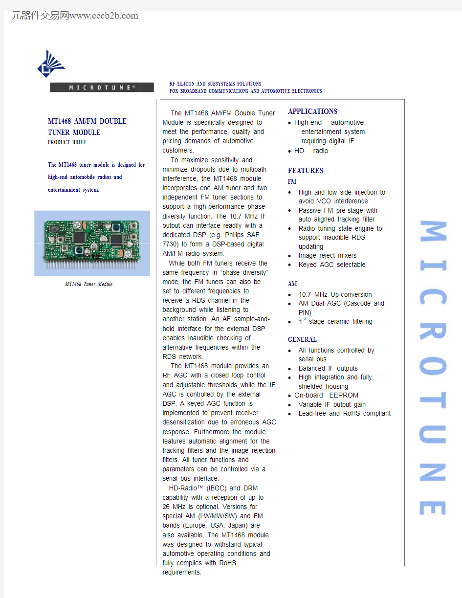
MT1468 Tuner Module
The MT1468 AM/FM Double Tuner Module is specifically designed to meet the performance, quality and pricing demands of automotive customers. To maximize sensitivity and minimize dropouts due to multipath interference, the MT1468 module incorporates one AM tuner and two independent FM tuner sections to support a high-performance phase diversity function. The 10.7 MHz IF output can interface readily with a dedicated DSP (e.g. Philips SAF 7730) to form a DSP-based digital AM/FM radio system. While both FM tuners receive the same frequency in “phase diversity” mode, the FM tuners can also be set to different frequencies to receive a RDS channel in the background while listening to another station. An AF sample-andhold interface for the external DSP enables inaudible checking of alternative frequencies within the RDS network. The MT1468 module provides an RF AGC with a closed loop control and adjustable thresholds while the IF AGC is controlled by the external DSP. A keyed AGC function is implemented to prevent receiver desensitization due to erroneous AGC response. Furthermore the module features automatic alignment for the tracking filters and the image rejection filters. All tuner functions and parameters can be controlled via a serial bus interface. HD-Radio? (IBOC) and DRM capability with a reception of up to 26 MHz is optional. Versions for special AM (LW/MW/SW) and FM bands (Europe, USA, Japan) are also available. The MT1468 module was designed to withstand typical automotive operating conditions and fully complies with RoHS requirements.
APPLICATIONS
? High-end automotive entertainment system requiring digital IF HD radio
?
FEATURES
FM
? ? ? High and low side injection to avoid VCO interference Passive FM pre-stage with auto aligned tracking filter Radio tuning state engine to support inaudible RDS updating Image reject mixers Keyed AGC selectable
? ?
AM
? ? ? 10.7 MHz Up-conversion AM Dual AGC (Cascode and PIN) 1st stage ceramic filtering
GENERAL
? ? ? ? ? ? All functions controlled by serial bus Balanced IF outputs High integration and fully shielded housing On-board EEPROM Variable IF output gain Lead-free and RoHS compliant
元器件交易网https://www.doczj.com/doc/6b11014540.html,
MT1468 A M /F M DOUBL E TU N ER MODUL E
PRODUCT BRIEF
RECOMMENDED OPERATING CONDITIONS
PARAMETER
8.5 V Power Supply Current AM mode Current FM mode Voltage Operating temperature range Storage temperature
ELECTRICAL CHARACTERISTICS*
MAX UNIT
mA mA V °C °C
MIN
TYP
130 100 8.5
PARAMETER
MIN
TYP
MAX
91 108 288 1720 6,295 26,100
UNIT
MHz MHz KHz KHz KHz KHz dBμV dB dB dB dB dBμV dB dB dB dB % dB
-40 -40
85 95
INPUT/OUTPUT CHARACTERISTICS
PARAMETER
Antenna Input AM mode Input Capacitance, AGC inactive Input Conductance, AGC inactive Input Conductance, AGC active Antenna Input FM mode Input Impedance, AGC inactive VSWR, AGC inactive Input Resistance, AGC active Keyed AGC Inputs SDA SCL Intermediate Frequency Output Max. balanced output Voltage Output resistance AF Sample Output * AF Hold Output * Reference Frequency Inputs External Frequency External input current Input Resistance IF AGC LSB/MSB LOW-level input voltage HIGH-level input voltage
MIN
TYP
60 1
MAX
UNIT
pF mS mS ?
3.3 50
4 10 ? 0.4 1.4 V SDA and SCL HIGH and LOW levels are specified according to a 3.3V I2C-Bus. The bus pins also tolerate thresholds of a 5 V bus. 10.7 MHz 1.4 V 500 ? 1.2 mA 1.2 mA 100 500 5 -0.3 2 1 5.3 KHz μA ? V V
Receiving frequency range (depends on version) FM mode Japan 76 FM mode Europe/USA 87.5 AM LW mode 144 AM MW mode 520 AM SW mode 5,730 DRM (optional) 144 AM Parameters Sensitivity: RF level for S+N/N = 22 26dB S+N/N at RF input = 60dBμV 60 IF rejection (10.7MHz) 96 Image rejection IF1 = tuned 85 frequency + 21.4MHz Selectivity ± 9 KHz 70 FM Parameters Sensitivity: RF level for S+N/N = 4.5 26dB S+N/N (Mono) at RF input = 60 54dBμV IF rejection (10.7MHz) 100 Image rejection IF1 = tuned 60 frequency + 21.4 MHz AM suppression 76 Distortion at RF level = 100dBμV 0.1 Selectivity ± 100 kHz 65
*Electrical characteristics measured with Philips backend DSP SAF7730 and antenna dummy causing a loss of 6 dB
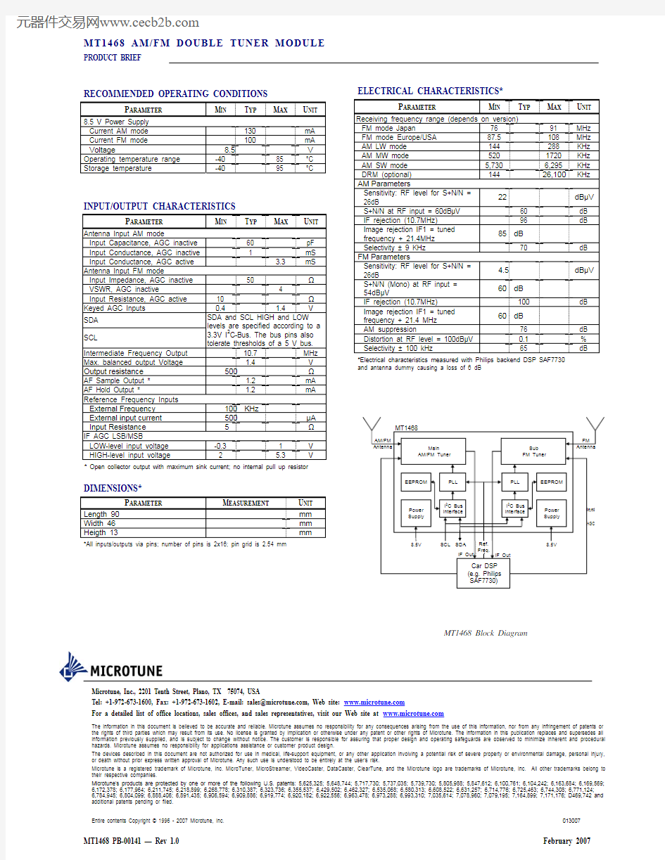
MT1468
AM/FM Antenna Main AM/FM Tuner Sub FM Tuner FM Antenna
* Open collector output with maximum sink current; no internal pull up resistor
DIMENSIONS*
keyed AGC
EEPROM
PLL
PLL
EEPROM
PARAMETER
Length Width Heigth
MEASUREMENT
90 46 13
UNIT
mm mm mm
keyed AGC
Power Supply
I2C Bus Interface
I2C Bus Interface
Power Supply
*All inputs/outputs via pins; number of pins is 2x16; pin grid is 2.54 mm
8.5V
SCL SDA IF Out
Ref. Freq.
8.5V IF Out
Car DSP (e.g. Philips SAF7730)
MT1468 Block Diagram
Microtune, Inc., 2201 Tenth Street, Plano, TX 75074, USA Tel: +1-972-673-1600, Fax: +1-972-673-1602, E-mail: sales@https://www.doczj.com/doc/6b11014540.html,, Web site: https://www.doczj.com/doc/6b11014540.html, For a detailed list of office locations, sales offices, and sales representatives, visit our Web site at https://www.doczj.com/doc/6b11014540.html,
The information in this document is believed to be accurate and reliable. Microtune assumes no responsibility for any consequences arising from the use of this information, nor from any infringement of patents or the rights of third parties which may result from its use. No license is granted by implication or otherwise under any patent or other rights of Microtune. The information in this publication replaces and supersedes all information previously supplied, and is subject to change without notice. The customer is responsible for assuring that proper design and operating safeguards are observed to minimize inherent and procedural hazards. Microtune assumes no responsibility for applications assistance or customer product design. The devices described in this document are not authorized for use in medical, life-support equipment, or any other application involving a potential risk of severe property or environmental damage, personal injury, or death without prior express written approval of Microtune. Any such use is understood to be entirely at the user’s risk. Microtune is a registered trademark of Microtune, Inc. MicroTuner, MicroStreamer, VideoCaster, DataCaster, ClearTune, and the Microtune logo are trademarks of Microtune, Inc. All other trademarks belong to their respective companies. Microtune’s products are protected by one or more of the following U.S. patents: 5,625,325; 5,648,744; 5,717,730; 5,737,035; 5,739,730; 5,805,988; 5,847,612; 6,100,761; 6,104,242; 6,163,684; 6,169,569; 6,172,378; 6,177,964; 6,211,745; 6,218,899; 6,268,778; 6,310,387; 6,323,736; 6,355,537; 6,429,502; 6,462,327; 6,535,068; 6,580,313; 6,608,522; 6,631,257; 6,714,776; 6,725,463; 6,744,308; 6,771,124; 6,784,945; 6,804,099; 6,888,406; 6,891,435; 6,906,594; 6,909,886; 6,919,774; 6,920,182; 6,922,556; 6,963,478; 6,973,288; 6,993,310; 7,035,614; 7,078,960; 7,079,195; 7,164,899; 7,171,176; D469,742 and additional patents pending or filed. Entire contents Copyright ? 1996 - 2007 Microtune, Inc. 013007
MT1468 PB-00141 — Rev 1.0
February 2007