CFD simulation and optimization of
the ventilation for subway side-platform Feng-Dong Yuan *, Shi-Jun You
Abstract
To obtain the velocity and temperature field of subway station and the optimized ventilation mode of subway side-platform station, this paper takes the evaluation and optimization of the ventilation for subway side-platform station as main line, builds three dimensional models of original and optimization design of the existed and rebuilt station. And using the two-equation turbulence model as its physics model, the thesis makes computational fluid dynamics (CFD) simulation to subway side-platform station with the boundary conditions collected for simulation computation through field measurement. It is found that the two-equation turbulence model can be used to predict velocity field and temperature field at the station under some reasonable presumptions in the investigation and study. At last, an optimization ventilation mode of subway side-platform station was put forward.
1. Introduction
Computational fluid dynamics (CFD) software is commonly used to simulate fluid flows, particularly in complex environments (Chow and Li, 1999; Zhang et al., 2006;Moureh and Flick, 2003). CFD is capable of simulating a wide variety of fluid problems (Gan and Riffat, 2004;Somarathne et al., 2005; Papakonstantinou et al., 2000;Karimipanah and Awbi, 2002). CFD models can be realistically modeled without investing in more costly experimental method (Betta et al., 2004; Allocca et al., 2003;Moureh and Flick, 2003). So CFD is now a popular design tool for engineers from different disciplines
for pursuing an optimum design due to the high cost, complexity, and limited information obtained from experimental methods (Li and Chow, 2003; Vardy et al., 2003; Katolidoy and Jicha,2003). Tunnel ventilation system design can be developed in depth from the predictions of various parameters, such as vehicle emission dispersion, visibility, air velocity, etc. (Li and Chow, 2003; Yau et al., 2003; Gehrke et al., 2003).
Earlier CFD simulations of tunnel ventilation system mainly focus on emergency situation as fire condition (Modic, 2003; Carvel et al., 2001; Casale, 2003). Many scientists and research workers (Waterson and Lavedrine, 2003; Sigl and Rieker, 2000; Gao et al., 2004; Tajadura et al., 2006) have done much work on this. This paper studied the performance of CFD simulation on subway environment control system which has not been studied by other paper or research report. It is essential to calculate and simulate the different designs before the construction begins, since the investment in subway’s construction is huge and the subway should run up for a few decade years. The ventilation of subway is crucial that the passengers should have fresh and high quality air (Lowndes et al.,2004; Luo and Roux, 2004). Then if emergency occurred that the well-designed ventilation system can save many people’s life and belongings (Chow and Li, 1999; Modic,2003; Carvel et al., 2001). The characteristics of emergency situation have been well investigated, but there have been few studies in air distribution of side-platform in normal conditions.
The development of large capacity and high speed computer and computational fluid dynamics technology makes it possible to use CFD technology to predict the air distribution and optimize the design project of subway ventilation system. Based on the human-oriented design intention in subway ventilation system, this study simulated and analyzed the ventilation system of existent station and original design of rebuilt
stations of Tianjin subway in China with the professional software AIRPAK, and then found the optimum ventilation project for the ventilation and structure of rebuilt stations.
2. Ventilation system
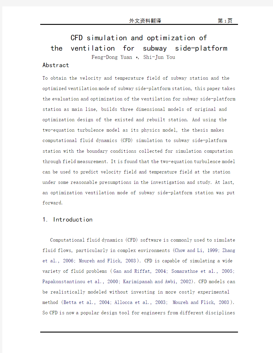
Tianjin Metro, the secondly-built subway in China, will be rebuilt to meet the demand of urban development and expected to be available for Beijing 2008 Olympic Games. The existent subway has eight stations, with a total length of 7.335 km and a 0.972 km average interval. For sake of saving the cost of engineering, the existent subway will continue to run and the stations will be rebuilt in the rebuilding Line 1 of Tianjin subway. Although different existent stations of Tianjin Metro have different structures and geometries, the Southwest Station is the most typical one. So the Southwest Station model was used to simulate and analyze in the study. Its geometry model is shown in Fig. 1.
2.1. The structure and original ventilation mode of existent station
T he subway has two run-lines. The structure of Southwest Station is, length width height = 74.4 m(L) 18.7 m(W) 4.4 m(H), which is a typical side-platform station. Each side has only one passageway (length height = 6.4 m(L) 2.9 m(H)). The middle of station is the space for passengers to wait for the vehicle. The platform mechanical ventilation is realized with two jet openings located at each end of station and the supply air jets towards train and track. There is no mechanical exhaust system at the station and air is removed mechanically by tunnel fans and naturally by the exits of the station.
2.2. The design structure and ventilation of rebuilt station
The predicted passenger flow volume increase greatly and the dimension of the original station is too small, so in the rebuilding design, the structure of subway station is changed to, (length width height = 132 m(L) 17.438 m(W) 4.65 m(H)), and each side has two passageways. The design volume flow of Southwest Station is 400000 m3/h. For most existent stations, the platform height is only 2.9 m, which is too low to set ceiling ducts.
So in the original design, there are two grille vents at each end of the platform to supply fresh air along the platform length direction and two grille vents to jet air breadthways towards trains. The design velocity of each lengthways grille vent is 5.54 m/s. For each breadthways vent, it is 5.28 m/s. Under the platform, 80 grille vents of the same velocity (4.62 m/s, 40 for each platform of the station) are responsible for exhaust.
3. CFD simulation and optimization
The application of CFD simulation in the indoor environment is based on conversation equations of energy, mass and momentum of incompressible air. The study adopted a turbulence energy model that is the two-equation turbulence model advanced by Launder and Spalding. And it integrated the governing equation on the capital control volumes and discretized in the definite grids, at last simulated and computed with the AIRPAK software.
3.1. Preceding simplifications and presumptions
Because of mechanical ventilation and the existence of train-driven piston wind, the turbulence on platform is transient and complex. Unless some simplifications and presumptions are made, the mathematics model of
three-dimensional flow is not expressed and the result is divergent. While ensuring the reliability of the computation results, some preceding simplifications and presumptions have to be taken.
(1)The period of maximum air velocity is paid attention to in the transient
process. Apparently the maximum air velocity is reached at the period when train stops at or starts away from the station (Yau et al., 2003;
Gehrke et al., 2003), so the period the simulation concerns about the best period of time for simulation is from the point when at the section of ‘x = 0.0 m’ (Fig. 1) and the air velocity begin to change under piston-effect to the point when train totally stops at the station (defined as a ‘pulling-in cycle’).
(2) Though the pulling-in cycle is a transient process, it is simplified to a steady process.
(3) Because the process is presumed to a steady process, the transient velocity of test sections, which was tested in Southwest Station in pulling-in cycle, is presumed to the time-averaged velocity of test sections.
(4) The volume flow driven into the station by pulling-in train is determined by such factors as BR (blocking ratio, the ratio of train cross-section area to tunnel cross-section area), the length of the train and the resistance of station etc. For existent and new stations, BRs are almost the same.
Although the length of the latter train doubles that of the former which may increase the piston flow volume, the resistance of latter is greater than that of the former which may counteract this increase. So it is presumed that the piston flow volume is same for both existent and new station and that the volume flow through the passenger exits is also same. Based on this presumption, the results of the field measurements at the existent station can be used as velocity boundary conditions to predict velocity filed of new station.
3.2. Original conditions
To obtain the boundary conditions for computation and simulation, such as the air velocity and temperature of enclosure, measures were done by times at Southwest Station.
All data are recorded during a complete pulling-in cycle. The air velocities were measured by the multichannel anemone-master hotwire anemoscope and infrared thermometer is used to measure the temperature of the walls of the station which are taken as the constant temperature thermal conditions in the simulation.
3.2.1. Temperatures of enclosure
Divide the platform into five segments and select some typical test positions. The distributing temperature of enclosure is shown in Table 1. It can be seen from Table1 that all temperatures of enclosure are between 23 _C and 25 _C, there is little difference in all test positions, and the average temperature is 24 _C. So all temperatures of subway station’s walls is 24 _C in CFD computation and simulation.
3.2.2. Time-averaged air velocity above the platform
Fig. 1 is the location of test section and the layout of measuring points. The data measured include 12 transient velocities in each section (A –H in Fig. 1), which were deal with section ’s time-averaged velocities in the period, 12 point ’s velocities of passageway, which is used to acquire the average flow, and the velocities of each end of station, which is used to acquire the average piston flow volume.
Fig. 2 is the lengthways velocities measured of platform sections, m ax V is the maximum air velocity, m in V is the minimum air velocity and avc V is the
average air velocity. Fig. 2 shows that the maximum air velocity is at the passageway. At the passageway the change of air velocity is about 2.25 m/s, which is the maximum and indicates that the passageway is the position effected most by the piston wind effect, and the air velocity of section D and E after the passageway is almost the same, which indicates that the piston wind can hardly effect the air velocity after the passageway.
CFD模拟和地铁站台的优化通风
Feng-Dong Yuan *, Shi-Jun You
摘要
获得车站的速度和温度领域同时地铁站台的最优方式。这篇文章验证和在主要线路上的地铁通风的最优化。建造三个空间最初的模型和现存物的优化设计和重建车站。并且用两个二平衡空气紊乱模型同样与它的物理模型。这篇论文计算流体动力学(CFD)模拟地铁边台站,它的边界条件通过收集测量数据进行模拟计算。发现这两个流体公式模型可以被用于预知速度和温度在车站下的一些合理的假设下进行学习。最后这一个地铁车站站台的最优化通风方案被提出来了。
1.介绍
CFD(Computational fluid dynamics)软件通常是模拟流动性流程图。特别是在复杂的环境计量中(Chow and Li, 1999; Zhang et al., 2006; Moureh and Flick, 2003)。CFD还可以模拟流动性问题的多种情况(Gan and Riffat, 2004; Somarathne et al., 2005; Papakonstantinou et al., 2000; Karimipanah and Awbi, 2002).CFD 模型是逼真的模型不需要昂贵的试验方法(Betta et al., 2004; Allocca et al., 2003; Moureh and Flick, 2003)。因而CFD是现在通俗的设计工具为了工程师从不同的规范寻找最优的设计方案,由于高成本的复杂性和条件的限制而通过模拟试验获得的方法(Li and Chow, 2003; Vardy et al., 2003; Katolidoy and Jicha, 2003)。隧道通风系统设计是能深度发展从不同的参数预测,例如车辆光的散射,离子,可见度,空气速度等。(Li and Chow, 2003; Yau et al., 2003; Gehrke et al., 2003).
早期的CFD隧道通风系统的模拟大体上集中在紧急情况如着火的情况下(Modic,
2003; Carvel et al., 2001; Casale, 2003)。多数科学家和研究者(Waterson and Lavedrine, 2003; Sigl and Rieker, 2000; Gao et al., 2004; Tajadura et al., 2006)已经做了许多这方面的工作。这篇文章是学习CFD模拟在地铁环境的控制是不能从其他文章或报告研究中得到的。它的本质是计算和模拟在结构成型以前,因为地铁投资建设是巨大的而且建设是要经过上十年的时间。地铁通风是至关重要的因为乘客需要新鲜和高质量的空气(Lowndes et al., 2004; Luo and Roux, 2004)。然后如果有紧急情况出现有计划的通风设计系统可以拯救生命和财产(Chow and Li, 1999; Modic, 2003; Carvel et al., 2001)。紧急情况的特征已经很好的研究,但是已经有一些研究关于在通常的情况下站台的空气分布状态。
大的发展和高速的电脑和计算的流动性动力学技术它有可能运用到CFD技术和预言空气的分布状态和优化的地铁通风系统设计的项目。基于在地铁通风系统的人工向导意图,这种研究模拟和分析已经存在的通风系统同时通过专业软件AIRPAK 得出天津地铁原先的车站位置需要重建,然后为重建车站找到最佳的通风的项目和结构。
2.通风系统
天津地铁是中国第二个建造的地铁,重建将会适应城市的发展并且希望用于2008年的北京奥运会。现存的车站有八个车站,其总长为7.335km和平均0.932km 的间距。由于工程的存款成本,那现存的地铁将继续运营并且车站的重建主要在天津地铁的一号线。尽管天津地铁现存的各种车站有着不同结构和几何结构,西南车站就是最典型的一个。几何模型展示在图符1中。
2.1.现存的车站结构和早期的通风模型
地铁有两条运营线路。西南车站的结构为长宽高=74.4m18.7m4.4m一个典型的边台车站。每边只有仅有一个通道(长宽=6.4m2.9m)。中间留出的空间是留给乘客等待机车。站台的机械通风是通过两个位于车站末端的喷射的敞口提供空气给火车和车轨。在车站没有机械排气系统,空气的流动是通过隧道的机械扇子和车站的
自然通风。
2.2. 设计结构和重建车站的通风
预计旅客大规模的增加和原先车站体积太小,所以重建设计的地铁结构体系将被设计为,长宽高=132m17.438m4.65m并且每边有两个乘客通道。西南车站的设计体积流量为400000 m3/h。其他大多数的现存车站站台高度仅有2.9m那对于设置小导管太矮了。
因此早期的设计里,有两个在每边平台末端的网格的通风口提供给站台纵向的新鲜空气和这两个通风口还向火车横向的喷射空气。横向网格通风口纵向设计风速为5.54m/s。每边的横向速度为5.28m/s.在站台下,80个相同风速的网格式通风口(4.62m/s,站台两边个40个)被用于排气是可靠的.
3. CFD模拟和优化设计
CFD模拟在户内环境的应用是基于能量,质量和动力的不可压缩空气守恒公式,研究采用二平衡空气紊乱能量模型被Launder和Spalding升级后的二平衡紊乱模型.它综合了governing equation在控制体积的重要性和使离散明确的表示在格子上,最后模拟并完成了AIRPAK软件.
3.1 前述的简化和假定
由于机械通风和火车行驶所带来的风,所以站台上的空气紊乱是短暂和复杂的.除非一些简化和假设能成立,否则那个三维的数学模型就不能表述从而使得结果有分歧.然而为了确保计算结果的可靠性,一些限制的简化和假设不得不被提出来.
(1)最大风速的周期在短暂的过程中是值得注意的.很显然最大风速是在火
车停或行驶离开车站这个周期中达到的(Yau et al., 2003;Gehrke et al., 2003),所以周期模拟的最好时间从x=0.0m(见图1)的地方开始并且空气速度正
在活塞效应下向另一个点,当火车完全在车站停下来后结束.(定义为一个“拉力-周期”)
图1:
(2)尽管“拉力-周期”是一个短暂的过程,但是他被简化为一个稳定的过程.
(3)因为那过程被假定为一个稳定的过程,在西南车站“拉力-周期”测试区的瞬时速度被假定为这个测试区的时间平均速度.
(4)体积流动通过“拉力-周期”打入车站决定于这些因素BR(阻碍率,火车穿越面积和隧道穿越面积之比),火车的长度和车站的阻力等等.对于原来的还是新的车站,BR都几乎是一样的.尽管后来的火车长度是原先火车长度的两倍,用于提高活塞活动的体积,同样由于体积的增大使得后来的比原先的火车所受到的阻力也更大了.所以假设原来和新的车站活塞活动体积是一样的,乘客出来是的活动体积也是相等的.基于上述假设,用于现存车站的测量结果可作为预算新的车站的速度边界条件.
3.2 原始条件
获得了计算的边界条件和模拟,例如空气流动速度和站内温度,按时对西南测量得出的.所有的数据的收集都在一个完全的“拉力-周期”过程中.空气速度的测量是通过多波段的海葵大师热线风速仪,红外线温度计测量车站墙的温度,车站的温度
在模拟中被视为恒定不变的.
3.2.1 站内温度
将站台分为5段并且选择一些典型的位置作为测点.站内温度的分布如表1.我们可以从表1中看到站内所有的温度都在23-25度之间,所有测点有一点点不同,平均温度为24度.所以在CFD 计算和模拟中地铁站内墙的温度均为24度.
3.2.2 站台上的平均时间风速
图1是 测试区的位置和测量点的布局图.数据测量的是包括每个站的瞬时速度(在图1中A-H 点),在一个周期中处理为区内的时间平均速度,过道12点的速度用于获得平均流速,车站末端的每个速度用于获得平均活塞活动体积.
图2是测量站台区域的纵向风速, m ax V 为最大空气流动速度, m in V 为最小空气流
动速度, avc V 为空气平均流动速度.图2显示了过道中的最大空气流动速度.在过道中
空气流动速度的变化量大约是2.25m/s,最大值标志着过道是最受活塞风效应影响的位置,并且空气流速在D 区和E 区之后几乎是相等的,这标志着在过道之后活塞风效应已经很难影响空气的平均流速了.
表1:
表2
外文出处: 《Exploiting Software How to Break Code》By Greg Hoglund, Gary McGraw Publisher : Addison Wesley Pub Date : February 17, 2004 ISBN : 0-201-78695-8 译文标题: JDBC接口技术 译文: JDBC是一种可用于执行SQL语句的JavaAPI(ApplicationProgrammingInterface应用程序设计接口)。它由一些Java语言编写的类和界面组成。JDBC为数据库应用开发人员、数据库前台工具开发人员提供了一种标准的应用程序设计接口,使开发人员可以用纯Java语言编写完整的数据库应用程序。 一、ODBC到JDBC的发展历程 说到JDBC,很容易让人联想到另一个十分熟悉的字眼“ODBC”。它们之间有没有联系呢?如果有,那么它们之间又是怎样的关系呢? ODBC是OpenDatabaseConnectivity的英文简写。它是一种用来在相关或不相关的数据库管理系统(DBMS)中存取数据的,用C语言实现的,标准应用程序数据接口。通过ODBCAPI,应用程序可以存取保存在多种不同数据库管理系统(DBMS)中的数据,而不论每个DBMS使用了何种数据存储格式和编程接口。 1.ODBC的结构模型 ODBC的结构包括四个主要部分:应用程序接口、驱动器管理器、数据库驱动器和数据源。应用程序接口:屏蔽不同的ODBC数据库驱动器之间函数调用的差别,为用户提供统一的SQL编程接口。 驱动器管理器:为应用程序装载数据库驱动器。 数据库驱动器:实现ODBC的函数调用,提供对特定数据源的SQL请求。如果需要,数据库驱动器将修改应用程序的请求,使得请求符合相关的DBMS所支持的文法。 数据源:由用户想要存取的数据以及与它相关的操作系统、DBMS和用于访问DBMS的网络平台组成。 虽然ODBC驱动器管理器的主要目的是加载数据库驱动器,以便ODBC函数调用,但是数据库驱动器本身也执行ODBC函数调用,并与数据库相互配合。因此当应用系统发出调用与数据源进行连接时,数据库驱动器能管理通信协议。当建立起与数据源的连接时,数据库驱动器便能处理应用系统向DBMS发出的请求,对分析或发自数据源的设计进行必要的翻译,并将结果返回给应用系统。 2.JDBC的诞生 自从Java语言于1995年5月正式公布以来,Java风靡全球。出现大量的用java语言编写的程序,其中也包括数据库应用程序。由于没有一个Java语言的API,编程人员不得不在Java程序中加入C语言的ODBC函数调用。这就使很多Java的优秀特性无法充分发挥,比如平台无关性、面向对象特性等。随着越来越多的编程人员对Java语言的日益喜爱,越来越多的公司在Java程序开发上投入的精力日益增加,对java语言接口的访问数据库的API 的要求越来越强烈。也由于ODBC的有其不足之处,比如它并不容易使用,没有面向对象的特性等等,SUN公司决定开发一Java语言为接口的数据库应用程序开发接口。在JDK1.x 版本中,JDBC只是一个可选部件,到了JDK1.1公布时,SQL类包(也就是JDBCAPI)
PA VEMENT PROBLEMS CAUSED BY COLLAPSIBLE SUBGRADES By Sandra L. Houston,1 Associate Member, ASCE (Reviewed by the Highway Division) ABSTRACT: Problem subgrade materials consisting of collapsible soils are com- mon in arid environments, which have climatic conditions and depositional and weathering processes favorable to their formation. Included herein is a discussion of predictive techniques that use commonly available laboratory equipment and testing methods for obtaining reliable estimates of the volume change for these problem soils. A method for predicting relevant stresses and corresponding collapse strains for typical pavement subgrades is presented. Relatively simple methods of evaluating potential volume change, based on results of familiar laboratory tests, are used. INTRODUCTION When a soil is given free access to water, it may decrease in volume, increase in volume, or do nothing. A soil that increases in volume is called a swelling or expansive soil, and a soil that decreases in volume is called a collapsible soil. The amount of volume change that occurs depends on the soil type and structure, the initial soil density, the imposed stress state, and the degree and extent of wetting. Subgrade materials comprised of soils that change volume upon wetting have caused distress to highways since the be- ginning of the professional practice and have cost many millions of dollars in roadway repairs. The prediction of the volume changes that may occur in the field is the first step in making an economic decision for dealing with these problem subgrade materials. Each project will have different design considerations, economic con- straints, and risk factors that will have to be taken into account. However, with a reliable method for making volume change predictions, the best design relative to the subgrade soils becomes a matter of economic comparison, and a much more rational design approach may be made. For example, typical techniques for dealing with expansive clays include: (1) In situ treatments with substances such as lime, cement, or fly-ash; (2) seepage barriers and/ or drainage systems; or (3) a computing of the serviceability loss and a mod- ification of the design to "accept" the anticipated expansion. In order to make the most economical decision, the amount of volume change (especially non- uniform volume change) must be accurately estimated, and the degree of road roughness evaluated from these data. Similarly, alternative design techniques are available for any roadway problem. The emphasis here will be placed on presenting economical and simple methods for: (1) Determining whether the subgrade materials are collapsible; and (2) estimating the amount of volume change that is likely to occur in the 'Asst. Prof., Ctr. for Advanced Res. in Transp., Arizona State Univ., Tempe, AZ 85287. Note. Discussion open until April 1, 1989. To extend the closing date one month,
毕业设计(论文)外文文献翻译 文献、资料中文题目:软件开发概念和设计方法文献、资料英文题目: 文献、资料来源: 文献、资料发表(出版)日期: 院(部): 专业: 班级: 姓名: 学号: 指导教师: 翻译日期: 2017.02.14
外文资料原文 Software Development Concepts and Design Methodologies During the 1960s, ma inframes and higher level programming languages were applied to man y problems including human resource s yste ms,reservation s yste ms, and manufacturing s yste ms. Computers and software were seen as the cure all for man y bu siness issues were some times applied blindly. S yste ms sometimes failed to solve the problem for which the y were designed for man y reasons including: ?Inability to sufficiently understand complex problems ?Not sufficiently taking into account end-u ser needs, the organizational environ ment, and performance tradeoffs ?Inability to accurately estimate development time and operational costs ?Lack of framework for consistent and regular customer communications At this time, the concept of structured programming, top-down design, stepwise refinement,and modularity e merged. Structured programming is still the most dominant approach to software engineering and is still evo lving. These failures led to the concept of "software engineering" based upon the idea that an engineering-like discipl ine could be applied to software design and develop ment. Software design is a process where the software designer applies techniques and principles to produce a conceptual model that de scribes and defines a solution to a problem. In the beginning, this des ign process has not been well structured and the model does not alwa ys accurately represent the problem of software development. However,design methodologies have been evolving to accommo date changes in technolog y coupled with our increased understanding of development processes. Whereas early desig n methods addressed specific aspects of the
转型衰退时期的土木工程研究 Sergios Lambropoulosa[1], John-Paris Pantouvakisb, Marina Marinellic 摘要 最近的全球经济和金融危机导致许多国家的经济陷入衰退,特别是在欧盟的周边。这些国家目前面临的民用建筑基础设施的公共投资和私人投资显著收缩,导致在民事特别是在民用建筑方向的失业。因此,在所有国家在经济衰退的专业发展对于土木工程应届毕业生来说是努力和资历的不相称的研究,因为他们很少有机会在实践中积累经验和知识,这些逐渐成为过时的经验和知识。在这种情况下,对于技术性大学在国家经济衰退的计划和实施的土木工程研究大纲的一个实质性的改革势在必行。目的是使毕业生拓宽他们的专业活动的范围,提高他们的就业能力。 在本文中,提出了土木工程研究课程的不断扩大,特别是在发展的光毕业生的潜在的项目,计划和投资组合管理。在这个方向上,一个全面的文献回顾,包括ASCE体为第二十一世纪,IPMA的能力的基础知识,建议在其他:显著增加所提供的模块和项目管理在战略管理中添加新的模块,领导行为,配送管理,组织和环境等;提供足够的专业训练五年的大学的研究;并由专业机构促进应届大学生认证。建议通过改革教学大纲为土木工程研究目前由国家技术提供了例证雅典大学。 1引言 土木工程研究(CES)蓬勃发展,是在第二次世界大战后。土木工程师的出现最初是由重建被摧毁的巨大需求所致,目的是更多和更好的社会追求。但是很快,这种演变一个长期的趋势,因为政府为了努力实现经济发展,采取了全世界的凯恩斯主义的理论,即公共基础设施投资作为动力。首先积极的结果导致公民为了更好的生活条件(住房,旅游等)和增加私人投资基础设施而创造机会。这些现象再国家的发展中尤为为明显。虽然前景并不明朗(例如,世界石油危机在70年代),在80年代领先的国家采用新自由主义经济的方法(如里根经济政策),这是最近的金融危机及金融危机造成的后果(即收缩的基础设施投资,在技术部门的高失业率),消除发展前途无限的误区。 技术教育的大学所认可的大量研究土木工程部。旧学校拓展专业并且新的学校建成,并招收许多学生。由于高的职业声望,薪酬,吸引高质量的学校的学生。在工程量的增加和科学技术的发展,导致到极强的专业性,无论是在研究还是工作当中。结构工程师,液压工程师,交通工程师等,都属于土木工程。试图在不同的国家采用专业性的权利,不同的解决方案,,从一个统一的大学学历和广泛的专业化的一般职业许可证。这个问题在许多其他行业成为关键。国际专业协会的专家和机构所确定的国家性检查机构,经过考试后,他们证明不仅是行业的新来者,而且专家通过时间来确定进展情况。尽管在很多情况下,这些证书虽然没有国家接受,他们赞赏和公认的世界。 在试图改革大学研究(不仅在土木工程)更接近市场需求的过程中,欧盟确定了1999博洛尼亚宣言,它引入了一个二能级系统。第一级度(例如,一个三年的学士)是进入
姓名: 学号: 10447425 X X 大学 毕业设计(论文)外文翻译 (2014届) 外文题目Developments in excavation bracing systems 译文题目开挖工程支撑体系的发展 外文出处Tunnelling and Underground Space Technology 31 (2012) 107–116 学生XXX 学院XXXX 专业班级XXXXX 校内指导教师XXX 专业技术职务XXXXX 校外指导老师专业技术职务 二○一三年十二月
开挖工程支撑体系的发展 1.引言 几乎所有土木工程建设项目(如建筑物,道路,隧道,桥梁,污水处理厂,管道,下水道)都涉及泥土挖掘的一些工程量。往往由于由相邻的结构,特性线,或使用权空间的限制,必须要一个土地固定系统,以允许土壤被挖掘到所需的深度。历史上,许多挖掘支撑系统已经开发出来。其中,现在比较常见的几种方法是:板桩,钻孔桩墙,泥浆墙。 土地固定系统的选择是由技术性能要求和施工可行性(例如手段,方法)决定的,包括执行的可靠性,而成本考虑了这些之后,其他问题也得到解决。通常环境后果(用于处理废泥浆和钻井液如监管要求)也非常被关注(邱阳、1998)。 土地固定系统通常是建设项目的较大的一个组成部分。如果不能按时完成项目,将极大地影响总成本。通常首先建造支撑,在许多情况下,临时支撑系统是用于支持在挖掘以允许进行不断施工,直到永久系统被构造。临时系统可以被去除或留在原处。 打桩时,因撞击或振动它们可能会被赶入到位。在一般情况下,振动是最昂贵的方法,但只适合于松散颗粒材料,土壤中具有较高电阻(例如,通过鹅卵石)的不能使用。采用打入桩系统通常是中间的成本和适合于软沉积物(包括粘性和非粘性),只要该矿床是免费的鹅卵石或更大的岩石。 通常,垂直元素(例如桩)的前安装挖掘工程和水平元件(如内部支撑或绑回)被安装为挖掘工程的进行下去,从而限制了跨距长度,以便减少在垂直开发弯矩元素。在填充情况下,桩可先设置,从在斜坡的底部其嵌入悬挑起来,安装作为填充进步水平元素(如搭背或土钉)。如果滞后是用来保持垂直元素之间的土壤中,它被安装为挖掘工程的进行下去,或之前以填补位置。 吉尔- 马丁等人(2010)提供了一个数值计算程序,以获取圆形桩承受轴向载荷和统一标志(如悬臂桩)的单轴弯矩的最佳纵筋。他们开发的两种优化流程:用一个或两个直径为纵向钢筋。优化增强模式允许大量减少的设计要求钢筋的用量,这些减少纵向钢筋可达到50%相对传统的,均匀分布的加固方案。 加固桩集中纵向钢筋最佳的位置在受拉区。除了节约钢筋,所述非对称加强钢筋图案提高抗弯刚度,通过增加转动惯量的转化部分的时刻。这种增加的刚性可能会在一段时间内增加的变形与蠕变相关的费用。评估相对于传统的非对称加强桩的优点,对称,钢筋桩被服务的条件下全面测试来完成的,这种试验是为了验证结构的可行性和取得的变形的原位测量。 基于现场试验中,用于优化的加强图案的优点浇铸钻出孔(CIDH)在巴塞罗那的
外文翻译 专业机械设计制造及其自动化学生姓名刘链柱 班级机制111 学号1110101102 指导教师葛友华
外文资料名称: Design and performance evaluation of vacuum cleaners using cyclone technology 外文资料出处:Korean J. Chem. Eng., 23(6), (用外文写) 925-930 (2006) 附件: 1.外文资料翻译译文 2.外文原文
应用旋风技术真空吸尘器的设计和性能介绍 吉尔泰金,洪城铱昌,宰瑾李, 刘链柱译 摘要:旋风型分离器技术用于真空吸尘器 - 轴向进流旋风和切向进气道流旋风有效地收集粉尘和降低压力降已被实验研究。优化设计等因素作为集尘效率,压降,并切成尺寸被粒度对应于分级收集的50%的效率进行了研究。颗粒切成大小降低入口面积,体直径,减小涡取景器直径的旋风。切向入口的双流量气旋具有良好的性能考虑的350毫米汞柱的低压降和为1.5μm的质量中位直径在1米3的流量的截止尺寸。一使用切向入口的双流量旋风吸尘器示出了势是一种有效的方法,用于收集在家庭中产生的粉尘。 摘要及关键词:吸尘器; 粉尘; 旋风分离器 引言 我们这个时代的很大一部分都花在了房子,工作场所,或其他建筑,因此,室内空间应该是既舒适情绪和卫生。但室内空气中含有超过室外空气因气密性的二次污染物,毒物,食品气味。这是通过使用产生在建筑中的新材料和设备。真空吸尘器为代表的家电去除有害物质从地板到地毯所用的商用真空吸尘器房子由纸过滤,预过滤器和排气过滤器通过洁净的空气排放到大气中。虽然真空吸尘器是方便在使用中,吸入压力下降说唱空转成比例地清洗的时间,以及纸过滤器也应定期更换,由于压力下降,气味和细菌通过纸过滤器内的残留粉尘。 图1示出了大气气溶胶的粒度分布通常是双峰形,在粗颗粒(>2.0微米)模式为主要的外部来源,如风吹尘,海盐喷雾,火山,从工厂直接排放和车辆废气排放,以及那些在细颗粒模式包括燃烧或光化学反应。表1显示模式,典型的大气航空的直径和质量浓度溶胶被许多研究者测量。精细模式在0.18?0.36 在5.7到25微米尺寸范围微米尺寸范围。质量浓度为2?205微克,可直接在大气气溶胶和 3.85至36.3μg/m3柴油气溶胶。
项目成本控制 一、引言 项目是企业形象的窗口和效益的源泉。随着市场竞争日趋激烈,工程质量、文明施工要求不断提高,材料价格波动起伏,以及其他种种不确定因素的影响,使得项目运作处于较为严峻的环境之中。由此可见项目的成本控制是贯穿在工程建设自招投标阶段直到竣工验收的全过程,它是企业全面成本管理的重要环节,必须在组织和控制措施上给于高度的重视,以期达到提高企业经济效益的目的。 二、概述 工程施工项目成本控制,指在项目成本在成本发生和形成过程中,对生产经营所消耗的人力资源、物资资源和费用开支,进行指导、监督、调节和限制,及时预防、发现和纠正偏差从而把各项费用控制在计划成本的预定目标之内,以达到保证企业生产经营效益的目的。 三、施工企业成本控制原则 施工企业的成本控制是以施工项目成本控制为中心,施工项目成本控制原则是企业成本管理的基础和核心,施工企业项目经理部在对项目施工过程进行成本控制时,必须遵循以下基本原则。 3.1 成本最低化原则。施工项目成本控制的根本目的,在于通过成本管理的各种手段,促进不断降低施工项目成本,以达到可能实现最低的目标成本的要求。在实行成本最低化原则时,应注意降低成本的可能性和合理的成本最低化。一方面挖掘各种降低成本的能力,使可能性变为现实;另一方面要从实际出发,制定通过主观努力可能达到合理的最低成本水平。 3.2 全面成本控制原则。全面成本管理是全企业、全员和全过程的管理,亦称“三全”管理。项目成本的全员控制有一个系统的实质性内容,包括各部门、各单位的责任网络和班组经济核算等等,应防止成本控制人人有责,人人不管。项目成本的全过程控制要求成本控制工作要随着项目施工进展的各个阶段连续 进行,既不能疏漏,又不能时紧时松,应使施工项目成本自始至终置于有效的控制之下。 3.3 动态控制原则。施工项目是一次性的,成本控制应强调项目的中间控制,即动态控制。因为施工准备阶段的成本控制只是根据施工组织设计的具体内容确
I / 11 本科毕业设计外文翻译 <2018届) 论文题目基于WEB 的J2EE 的信息系统的方法研究 作者姓名[单击此处输入姓名] 指导教师[单击此处输入姓名] 学科(专业 > 所在学院计算机科学与技术学院 提交日期[时间 ]
基于WEB的J2EE的信息系统的方法研究 摘要:本文介绍基于工程的Java开发框架背后的概念,并介绍它如何用于IT 工程开发。因为有许多相同设计和开发工作在不同的方式下重复,而且并不总是符合最佳实践,所以许多开发框架建立了。我们已经定义了共同关注的问题和应用模式,代表有效解决办法的工具。开发框架提供:<1)从用户界面到数据集成的应用程序开发堆栈;<2)一个架构,基本环境及他们的相关技术,这些技术用来使用其他一些框架。架构定义了一个开发方法,其目的是协助客户开发工程。 关键词:J2EE 框架WEB开发 一、引言 软件工具包用来进行复杂的空间动态系统的非线性分析越来越多地使用基于Web的网络平台,以实现他们的用户界面,科学分析,分布仿真结果和科学家之间的信息交流。对于许多应用系统基于Web访问的非线性分析模拟软件成为一个重要组成部分。网络硬件和软件方面的密集技术变革[1]提供了比过去更多的自由选择机会[2]。因此,WEB平台的合理选择和发展对整个地区的非线性分析及其众多的应用程序具有越来越重要的意义。现阶段的WEB发展的特点是出现了大量的开源框架。框架将Web开发提到一个更高的水平,使基本功能的重复使用成为可能和从而提高了开发的生产力。 在某些情况下,开源框架没有提供常见问题的一个解决方案。出于这个原因,开发在开源框架的基础上建立自己的工程发展框架。本文旨在描述是一个基于Java的框架,该框架利用了开源框架并有助于开发基于Web的应用。通过分析现有的开源框架,本文提出了新的架构,基本环境及他们用来提高和利用其他一些框架的相关技术。架构定义了自己开发方法,其目的是协助客户开发和事例工程。 应用程序设计应该关注在工程中的重复利用。即使有独特的功能要求,也
( 二 〇 一 二 年 六 月 外文文献及翻译 题 目: About Buiding on the Structure Design 学生姓名: 学 院:土木工程学院 系 别:建筑工程系 专 业:土木工程(建筑工程方向) 班 级:土木08-4班 指导教师:
英文原文: Building construction concrete crack of prevention and processing Abstract The crack problem of concrete is a widespread existence but again difficult in solve of engineering actual problem, this text carried on a study analysis to a little bit familiar crack problem in the concrete engineering, and aim at concrete the circumstance put forward some prevention, processing measure. Keyword:Concrete crack prevention processing Foreword Concrete's ising 1 kind is anticipate by the freestone bone, cement, water and other mixture but formation of the in addition material of quality brittleness not and all material.Because the concrete construction transform with oneself, control etc. a series problem, harden model of in the concrete existence numerous tiny hole, spirit cave and tiny crack, is exactly because these beginning start blemish of existence just make the concrete present one some not and all the characteristic of quality.The tiny crack is a kind of harmless crack and accept concrete heavy, defend Shen and a little bit other use function not a creation to endanger.But after the concrete be subjected to lotus carry, difference in temperature etc. function, tiny crack would continuously of expand with connect, end formation we can see without the
Optimum blank design of an automobile sub-frame Jong-Yop Kim a ,Naksoo Kim a,*,Man-Sung Huh b a Department of Mechanical Engineering,Sogang University,Shinsu-dong 1,Mapo-ku,Seoul 121-742,South Korea b Hwa-shin Corporation,Young-chun,Kyung-buk,770-140,South Korea Received 17July 1998 Abstract A roll-back method is proposed to predict the optimum initial blank shape in the sheet metal forming process.The method takes the difference between the ?nal deformed shape and the target contour shape into account.Based on the method,a computer program composed of a blank design module,an FE-analysis program and a mesh generation module is developed.The roll-back method is applied to the drawing of a square cup with the ˉange of uniform size around its periphery,to con?rm its validity.Good agreement is recognized between the numerical results and the published results for initial blank shape and thickness strain distribution.The optimum blank shapes for two parts of an automobile sub-frame are designed.Both the thickness distribution and the level of punch load are improved with the designed blank.Also,the method is applied to design the weld line in a tailor-welded blank.It is concluded that the roll-back method is an effective and convenient method for an optimum blank shape design.#2000Elsevier Science S.A.All rights reserved. Keywords:Blank design;Sheet metal forming;Finite element method;Roll-back method
专业资料 学院: 专业:土木工程 姓名: 学号: 外文出处:Structural Systems to resist (用外文写) Lateral loads 附件:1.外文资料翻译译文;2.外文原文。
附件1:外文资料翻译译文 抗侧向荷载的结构体系 常用的结构体系 若已测出荷载量达数千万磅重,那么在高层建筑设计中就没有多少可以进行极其复杂的构思余地了。确实,较好的高层建筑普遍具有构思简单、表现明晰的特点。 这并不是说没有进行宏观构思的余地。实际上,正是因为有了这种宏观的构思,新奇的高层建筑体系才得以发展,可能更重要的是:几年以前才出现的一些新概念在今天的技术中已经变得平常了。 如果忽略一些与建筑材料密切相关的概念不谈,高层建筑里最为常用的结构体系便可分为如下几类: 1.抗弯矩框架。 2.支撑框架,包括偏心支撑框架。 3.剪力墙,包括钢板剪力墙。 4.筒中框架。 5.筒中筒结构。 6.核心交互结构。 7. 框格体系或束筒体系。 特别是由于最近趋向于更复杂的建筑形式,同时也需要增加刚度以抵抗几力和地震力,大多数高层建筑都具有由框架、支撑构架、剪力墙和相关体系相结合而构成的体系。而且,就较高的建筑物而言,大多数都是由交互式构件组成三维陈列。 将这些构件结合起来的方法正是高层建筑设计方法的本质。其结合方式需要在考虑环境、功能和费用后再发展,以便提供促使建筑发展达到新高度的有效结构。这并
不是说富于想象力的结构设计就能够创造出伟大建筑。正相反,有许多例优美的建筑仅得到结构工程师适当的支持就被创造出来了,然而,如果没有天赋甚厚的建筑师的创造力的指导,那么,得以发展的就只能是好的结构,并非是伟大的建筑。无论如何,要想创造出高层建筑真正非凡的设计,两者都需要最好的。 虽然在文献中通常可以见到有关这七种体系的全面性讨论,但是在这里还值得进一步讨论。设计方法的本质贯穿于整个讨论。设计方法的本质贯穿于整个讨论中。 抗弯矩框架 抗弯矩框架也许是低,中高度的建筑中常用的体系,它具有线性水平构件和垂直构件在接头处基本刚接之特点。这种框架用作独立的体系,或者和其他体系结合起来使用,以便提供所需要水平荷载抵抗力。对于较高的高层建筑,可能会发现该本系不宜作为独立体系,这是因为在侧向力的作用下难以调动足够的刚度。 我们可以利用STRESS,STRUDL 或者其他大量合适的计算机程序进行结构分析。所谓的门架法分析或悬臂法分析在当今的技术中无一席之地,由于柱梁节点固有柔性,并且由于初步设计应该力求突出体系的弱点,所以在初析中使用框架的中心距尺寸设计是司空惯的。当然,在设计的后期阶段,实际地评价结点的变形很有必要。 支撑框架 支撑框架实际上刚度比抗弯矩框架强,在高层建筑中也得到更广泛的应用。这种体系以其结点处铰接或则接的线性水平构件、垂直构件和斜撑构件而具特色,它通常与其他体系共同用于较高的建筑,并且作为一种独立的体系用在低、中高度的建筑中。
毕业设计(论文) 外文翻译 题目西安市水源工程中的 水电站设计 专业水利水电工程 班级 学生 指导教师 2016年
研究钢弧形闸门的动态稳定性 牛志国 河海大学水利水电工程学院,中国南京,邮编210098 nzg_197901@https://www.doczj.com/doc/6715818918.html,,niuzhiguo@https://www.doczj.com/doc/6715818918.html, 李同春 河海大学水利水电工程学院,中国南京,邮编210098 ltchhu@https://www.doczj.com/doc/6715818918.html, 摘要 由于钢弧形闸门的结构特征和弹力,调查对参数共振的弧形闸门的臂一直是研究领域的热点话题弧形弧形闸门的动力稳定性。在这个论文中,简化空间框架作为分析模型,根据弹性体薄壁结构的扰动方程和梁单元模型和薄壁结构的梁单元模型,动态不稳定区域的弧形闸门可以通过有限元的方法,应用有限元的方法计算动态不稳定性的主要区域的弧形弧形闸门工作。此外,结合物理和数值模型,对识别新方法的参数共振钢弧形闸门提出了调查,本文不仅是重要的改进弧形闸门的参数振动的计算方法,但也为进一步研究弧形弧形闸门结构的动态稳定性打下了坚实的基础。 简介 低举升力,没有门槽,好流型,和操作方便等优点,使钢弧形闸门已经广泛应用于水工建筑物。弧形闸门的结构特点是液压完全作用于弧形闸门,通过门叶和主大梁,所以弧形闸门臂是主要的组件确保弧形闸门安全操作。如果周期性轴向载荷作用于手臂,手臂的不稳定是在一定条件下可能发生。调查指出:在弧形闸门的20次事故中,除了极特殊的破坏情况下,弧形闸门的破坏的原因是弧形闸门臂的不稳定;此外,明显的动态作用下发生破坏。例如:张山闸,位于中国的江苏省,包括36个弧形闸门。当一个弧形闸门打开放水时,门被破坏了,而其他弧形闸门则关闭,受到静态静水压力仍然是一样的,很明显,一个动态的加载是造成的弧形闸门破坏一个主要因素。因此弧形闸门臂的动态不稳定是造成弧形闸门(特别是低水头的弧形闸门)破坏的主要原是毫无疑问。
Section 3 Design philosophy, design method and earth pressures 3.1 Design philosophy 3.1.1 General The design of earth retaining structures requires consideration of the interaction between the ground and the structure. It requires the performance of two sets of calculations: 1)a set of equilibrium calculations to determine the overall proportions and the geometry of the structure necessary to achieve equilibrium under the relevant earth pressures and forces; 2)structural design calculations to determine the size and properties of thestructural sections necessary to resist the bending moments and shear forces determined from the equilibrium calculations. Both sets of calculations are carried out for specific design situations (see 3.2.2) in accordance with the principles of limit state design. The selected design situations should be sufficiently Severe and varied so as to encompass all reasonable conditions which can be foreseen during the period of construction and the life of the retaining wall. 3.1.2 Limit state design This code of practice adopts the philosophy of limit state design. This philosophy does not impose upon the designer any special requirements as to the manner in which the safety and stability of the retaining wall may be achieved, whether by overall factors of safety, or partial factors of safety, or by other measures. Limit states (see 1.3.13) are classified into: a) ultimate limit states (see 3.1.3); b) serviceability limit states (see 3.1.4). Typical ultimate limit states are depicted in figure 3. Rupture states which are reached before collapse occurs are, for simplicity, also classified and
7 Rigid-Frame Structures A rigid-frame high-rise structure typically comprises parallel or orthogonally arranged bents consisting of columns and girders with moment resistant joints. Resistance to horizontal loading is provided by the bending resistance of the columns, girders, and joints. The continuity of the frame also contributes to resisting gravity loading, by reducing the moments in the girders. The advantages of a rigid frame are the simplicity and convenience of its rectangular form.Its unobstructed arrangement, clear of bracing members and structural walls, allows freedom internally for the layout and externally for the fenestration. Rig id frames are considered economical for buildings of up to' about 25 stories, above which their drift resistance is costly to control. If, however, a rigid frame is combined with shear walls or cores, the resulting structure is very much stiffer so that its height potential may extend up to 50 stories or more. A flat plate structure is very similar to a rigid frame, but with slabs replacing the girders As with a rigid frame, horizontal and vertical loadings are resisted in a flat plate structure by the flexural continuity between the vertical and horizontal components. As highly redundant structures, rigid frames are designed initially on the basis of approximate analyses, after which more rigorous analyses and checks can be made. The procedure may typically inc lude the following stages: 1. Estimation of gravity load forces in girders and columns by approximate method. 2. Preliminary estimate of member sizes based on gravity load forces with arbitrary increase in sizes to allow for horizontal loading. 3. Approximate allocation of horizontal loading to bents and preliminary analysis of member forces in bents. 4. Check on drift and adjustment of member sizes if necessary. 5. Check on strength of members for worst combination of gravity and horizontal loading, and adjustment of member sizes if necessary. 6. Computer analysis of total structure for more accurate check on member strengths and drift, with further adjustment of sizes where required. This stage may include the second-order P-Delta effects of gravity loading on the member forces and drift.. 7. Detailed design of members and connections.