1Scope This method is to determine the physical endur-ance of printed boards to sudden changes of temperature.It is designed to expose specimens to a series of high and low temperature excursions to cause physical fatigue.
2Applicable Documents
IPC-2221Generic Standard on Printed Board Design
3Test Specimen Coupon D from IPC-2221or other suit-able test coupon(see6.1a).
4Apparatus
4.1An automatically controlled dual temperature environ-mental test chamber or other dual chamber apparatus capable of maintaining–65,–55,–40or0°C+0–5°C[–85,–67,–40,+32°F+0–9°F]in the low temperature chamber and70,85,105,125,150or170+5–0°C[158,185,221, 257,302or338+9–0°F]in the high temperature chamber.
NOTE:The temperature extremes(high and low)that are required is dependent on the base material of the specimen that is to be tested(see6.1b and the temperatures listed in Table2).The recovery capacity of the test chambers shall be such that the internal chamber temperature shall reach the specified temperature within two minutes after the speci-men(s)have been transferred to the test chamber.Test con-ditions,if not otherwise stated in the applicable performance specification(see 6.1b),shall meet the requirements of Table2.
4.2An electrical resistance meter capable of accuracies of 0.5milliohm or better with Kelvin(four terminal)type leads.A Kelvin type double bridge or potentiometer of the specified accuracy may also be used.
5Procedure
5.1Preparation Wire up test specimen with Kelvin-type leads at the points where measurements will be made.
5.1.1Operate chamber(or chambers)and allow to stabilize at the high and low temperature required.Clamp or suspend-test specimen in the approximate center of the high tempera-ture chamber.Test specimens shall be placed approximately 13mm[0.5in]apart and aligned in a manner to permit maxi-mum heat transfer to test specimen(s).
5.2Test
5.2.1Thermal Shock Cycle
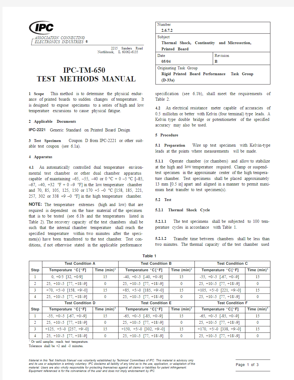
5.2.1.1The test specimens shall be subjected to100tem-perature cycles in accordance with Table1.
5.2.1.2Transfer time between chambers shall be less than two minutes.The thermal capacity of the test chamber used
Table1
Step
Test Condition A Test Condition B Test Condition C Temperature°C[°F]Time(min)1Temperature°C[°F]Time(min)1Temperature°C[°F]Time(min)1
10,+0/5[32,+0/9]15-40,+0/-5[-40,+0/-9]15-55,+0/-5[-67,+0/-9]15 225,+10/-5[77,+18/-9]025,+10/-5[77,+18/-9]025,+10/-5[77,+18/-9]0 3+70,+5/-0[158,+9/-0]15+85,+5/-0[185,+9/-0]15+105,+5/-0[221,+9/-0]15 425,+10/-5[77,+18/-9]025,+10/-5[77,+18/-9]025,+10/-5[77,+18/-9]0
Step
Test Condition D Test Condition E Test Condition F Temperature°C[°F]Time(min)1Temperature°C[°F]Time(min)1Temperature°C[°F]Time(min)1
1-55,+0/-5[-67,+0/-9]15-65,+0/-5[-85,+0/-9]15-65,+0/-5[-85,+0/-9]15 225,+10/-5[77,+18/-9]025,+10/-5[77,+18/-9]025,+10/-5[77,+18/-9]0 3+125,+5/-0[257,+9/-0]15+150,+5/-0[302,+9/-0]15+170,+5/-0[338,+9/-0]15 425,+10/-5[77,+18/-9]025,+10/-5[77,+18/-9]025,+10/-5[77,+18/-9]0
1Or until samples reach test temperature.
Tolerance shall be+2and-0minutes.
Material in this Test Methods Manual was voluntarily established by Technical Committees of IPC.This material is advisory only
and its use or adaptation is entirely voluntary.IPC disclaims all liability of any kind as to the use,application,or adaptation of this
https://www.doczj.com/doc/772389699.html,ers are also wholly responsible for protecting themselves against all claims or liabilities for patent infringement.
Equipment referenced is for the convenience of the user and does not imply endorsement by IPC.
Page1of3
shall be such that the ambient temperature shall reach the specified temperature within twp minutes after the test speci-men has been transferred to the appropriate chamber.5.2.1.3
Interconnection resistance measurements shall be
taken before the test,during the first cycle at high tempera-ture,and during the last cycle at high temperature.
5.3Evaluation
The maximum change in resistance
between the first and 100th cycle shall be evaluated for acceptability to the requirements of the applicable perfor-mance specification (see 6.1c).After testing,a minimum of three plated-through holes shall be microsectioned and shall be evaluated for acceptability to the requirements of the appli-cable performance specifications.
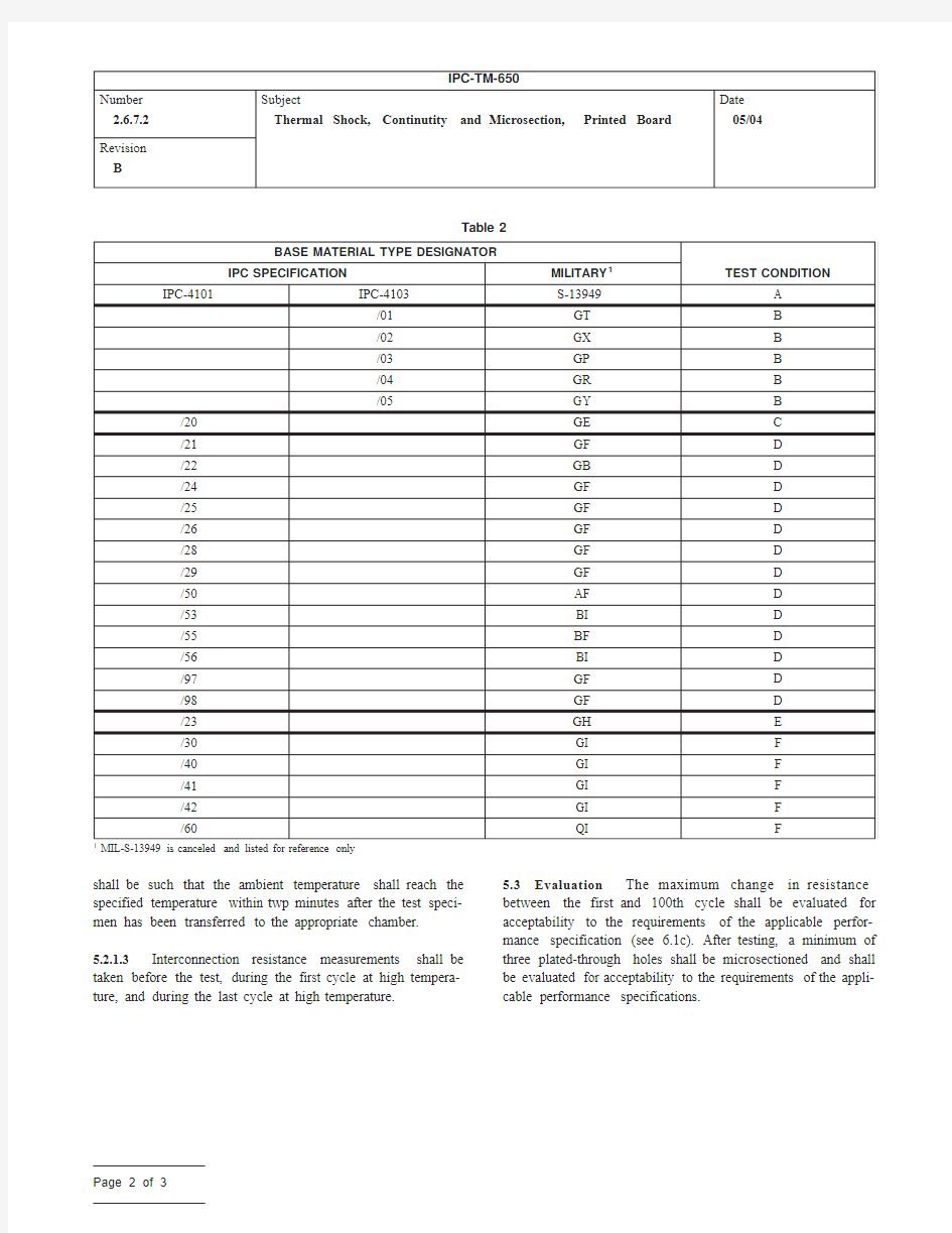
Table 2
BASE MATERIAL TYPE DESIGNATOR
TEST CONDITION
IPC SPECIFICATION
MILITARY 1
IPC-4101IPC-4103S-13949A /01GT B /02GX B /03GP B /04GR B /05
GY B /20GE C /21GF D /22GB D /24GF D /25GF D /26GF D /28GF D /29GF D /50AF D /53BI D /55BF D /56BI D /97GF D /98GF D /23GH E /30GI F /40GI F /41GI F /42GI F /60
QI
F
1
MIL-S-13949is canceled and listed for reference only
Revision B
Page 2of 3
Revision
B
6Notes
6.1The following details are to be specified in the applicable
performance specification:
a.Test specimen,if other than specified in3.
b.Test condition,if other than specified in4.1.
c.Maximum allowable change in resistance.
6.1.1Unless otherwise specified by the applicable perfor-
mance specification,the following base material types/
temperature ratings are recommended.
Page3of3