Agilent dc Electronic Loads Models N3300A-N3307A Technical Specifications
Increase your Manufacturing Test Throughput with Fast Electronic Loads
? Increase test system throughput
? Lower cost of ownership
? Decrease system development time
? Increase system reliability
? Increase system flexibility
? Stable operation down to zero volts
? dc connection terminal for ATE applications
Agilent Technologies
Today’s high volume manufac-turing requires optimization
of test system throughput, to maximize production volume without increasing floorspace. The N3300A Series electronic loads can help you in a number of ways to achieve this goal.
Reduced command processing time: Commands are processed more than 10 times faster than previ-ous electronic loads.
Automatically execute stored command sequences:“Lists”
of downloaded command sequences can execute indepen-dent of the computer, greatly reducing the electronic load command processing time
and computer interaction
time during product testing.
Programmable delay allows for either simultaneous or sequential load changes:This is the most efficient way to conduct testing of multiple output dc power supplies, simulating real-life loading patterns, with a minimum of programming commands.
Buffer measurement data: Voltage, current, and power measure-ments can be buffered for later readback to the computer, reducing computer interaction. Control measurement speed vs. accuracy:Decrease the number of measurement samples to achieve greater measurement speed, or increase the number of samples to achieve higher measurement accuracy. You Control rising and falling slew
rates separately:Reduce rate of
loading change when necessary
for DUT stability or to simulate
real life conditions, but other-
wise change load values at
maximum rate.
Increase System
Flexibility…for both
present and future
requirements
Most power supply and battery
charger test systems designed
today need to test a variety of
products and/or assemblies. In
the future, additional products
or assemblies may be needed.
A flexible family of electronic
loads makes present system
design and future growth
much easier.
Test low voltage power supplies:
The N3300A series electronic
loads operate with full stability
down to zero volts. Many other
electronic loads available today
have been found to become
unstable in the operating region
below one volt. When designing
power supply test platforms,
the trend towards lower voltage
requirements should be taken
into account. Refer to the
specification and supplemental
characteristic tables for details
of lower voltage operating
characteristics.
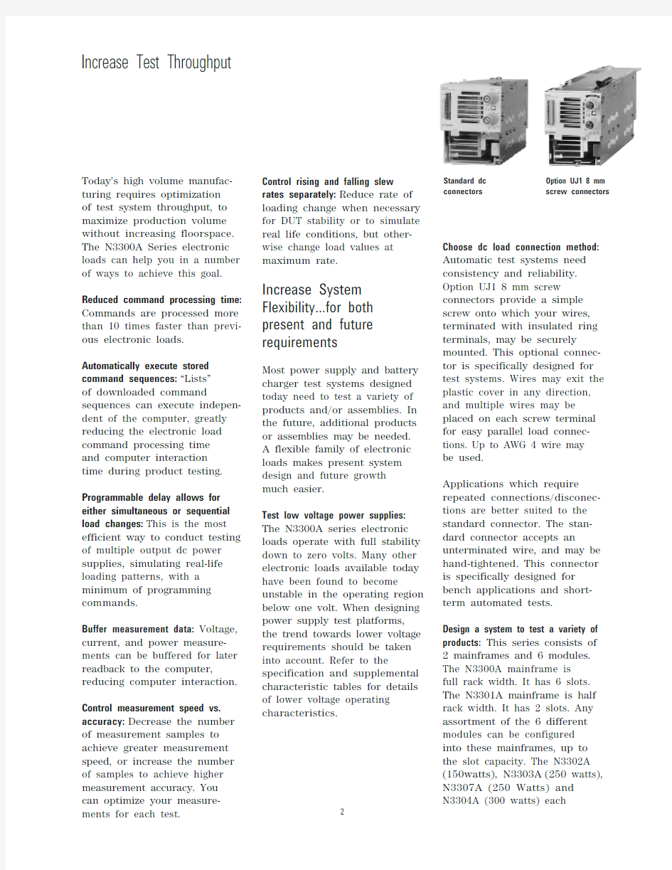
Choose dc load connection method:
Automatic test systems need
consistency and reliability.
Option UJ1 8 mm screw
connectors provide a simple
screw onto which your wires,
terminated with insulated ring
terminals, may be securely
mounted. This optional connec-
tor is specifically designed for
test systems. Wires may exit the
plastic cover in any direction,
and multiple wires may be
placed on each screw terminal
for easy parallel load connec-
tions. Up to AWG 4 wire may
be used.
Applications which require
repeated connections/disconec-
tions are better suited to the
standard connector. The stan-
dard connector accepts an
unterminated wire, and may be
hand-tightened. This connector
is specifically designed for
bench applications and short-
term automated tests.
Design a system to test a variety of
products: This series consists of
2 mainframes and 6 modules.
The N3300A mainframe is
full rack width. It has 6 slots.
The N3301A mainframe is half
rack width. It has 2 slots. Any
assortment of the 6 different
modules can be configured
into these mainframes, up to
the slot capacity. The N3302A
(150watts),N3303A(250 watts),
N3307A (250 Watts) and
Standard dc Option UJ1 8 mm
connectors screw connectors
Increase Test Throughput
require one slot. The N3305A (500 watts) and the N3306A (600 watts) each require 2 slots. The electronic load can be configured to supply exactly what you need now, and this modular design also allows for easy future reconfiguration.
Test high current power supplies: Electronic load modules can be operated in parallel to provide addition current sinking capa-bility.
Control the electronic load how you want to:GPIB, RS232, and man-ual use of the front panel all provide complete control of these electronic loads. There are also analog programming and monitoring ports for those applications that utilize non-standard interfaces, require custom waveforms, or utilize process control signals. Custom waveforms can also be created by downloading a “List” of load parameters. In addition, there is a built-in transient generator, which operates in all modes. Quickly create powerful and consistent software: All Agilent Technologies electronic loads use the SCPI (Standard Commands for Programmable Instruments) command set. This makes learning the com-mands easy, because they are the same format as all other SCPI instruments. The resulting code is virtually self-document-ing, and therefore easier to troubleshoot and modify in the future. Plug-n-Play drivers are also available to help you to
integrate the loads into your
standard software packages.
Make Measurements
Easily and Accurately
The 16-bit voltage, current and
power measurement system
provides both accuracy and
convenience. The alternative
is using a dmm (digital multi-
meter) and MUX (multiplexer)
along with a precision current
shunt and a lot of extra wiring.
Avoiding this complexity
increases system reliability
and makes the system easier to
design and support. Current
measurements in particular
are more consistently accurate
using the electronic load’s
internal system, because the
wiring associated with an
external precision current
shunt may pick up noise.
Measure with all load modules
simultaneously:Testing multiple-
output dc power supplies and
dc-dc converters can be very
time consuming if each output
must be tested sequentially. If
measurements are being made
through a MUX using one DMM,
this is what will happen. Using
the built-in measurement
capabilities of the N3300A
electronic loads, all outputs can
be measured simultaneously.
Alternatively, multiple single
output power sources can be
tested simultaneously.
Measure voltage and current simul-
taneously: The N3300A measure-
ment system has individual
but linked current and voltage
measurement systems. This
means that voltage and current
measurements are taken exactly
simultaneously, which gives a
true picture of the power
supply under test’s output at
a particular moment in time.
Some other electronic loads
which feature internal measure-
ment systems actually take cur-
rent and voltage measurements
sequentially, and therefore do
not give as accurate a picture
of momentary power.
Observe transient behavior using
waveform digitization: Transient
response and other dynamic
tests often require an oscillo-
scope. The N3300A has a flexi-
ble waveform digitizer with a
4096 data point buffer for
voltage and a 4096 data point
buffer for current. Under many
circumstances, this internal
digitizer will be adequate for
power supply test needs.
Current and voltage are
digitized simultaneously, and
the sampling rate and sample
window are programmable.
Some analysis functions are
provided, including RMS,
max and min.
Table A-1 states that 1.2 V
1.2 V
1.2 V
1.4 V
1.4 V
1.4 V
maximum current is
available down to 2 volts. Typically, however under normal operating conditions, the load can sink the maximum current down to the following voltages:
Typical Minimum Operating Voltage @ Full Scale Current
Constant Current Mode2
Low Range/High Range 3 A/30 A 1 A/10 A 6 A/60 A 6 A/60 A12 A/120 A 3 A/30 A
Regulation10 mA8 mA10 mA10 mA10 mA10 mA
Low Range Accuracy0.1% + 5 mA0.1% + 4 mA0.1% + 7.5 mA0.1% + 7.5 mA0.1% + 15 mA0.1% + 7.5 mA
High Range Accuracy0.1% + 10 mA0.1% + 7.5 mA0.1% + 15 mA0.1% + 15 mA0.1% + 37.5 mA0.1% + 15 mA Constant Voltage Mode2
Low Range/High Range 6 V/60 V24 V/240 V 6 V/60V15 V/150 V 6 V/60 V15 V/150 V
Regulation 5 mV10 mV10 mV10 mV20 mV10 mV
Low Range Accuracy0.1% + 3 mV0.1% + 10 mV0.1% + 3 mV0.1% + 10 mV0.1% + 3 mV0.1% + 10 mV
High Range Accuracy0.1% + 8 mV0.1% + 40 mV0.1% + 8 mV0.1% + 20 mV0.1% + 8 mV0.1% + 20 mV Constant Resistance Mode2
Range 1 0.067-4 ?0.2-48 ?0.033-2 ?0.033-5 ?0.017-1 ?0.067-10 ?
(I >10% of current rating)
Range 2 3.6-40 ?44-480 ? 1.8-20 ? 4.5-50 ?0.9-10 ?9-100 ?
(I >1% of current rating)
Range 3 36-400 ?440-4800 ?18-200 ?45-500 ?9-100 ?90-1000 ?
(I >0.1% of current rating)
Range 4 360-2000 ?4400-12000 ?180-2000 ?450-2500 ?90-1000 ?900-2500 ?
(I >0.01% of current rating)
Transient Generator
Frequency Range0.25 Hz - 10 kHz0.25 Hz - 10 kHz0.25 Hz - 10 kHz0.25 Hz - 10 kHz 0.25 Hz - 10 kHz0.25 Hz - 10 kHz
Pulse Width50 μs ±1% to 50 μs ±1% to50 μs ±1% to50 μs ±1% to50 μs ±1% to50 μs ±1% to
4 seconds ±1% 4 seconds ±1% 4 seconds ±1% 4 seconds ±1%4 seconds ±1% 4 seconds ±1% Current Measurement 2
Low Range/High Range 3 A/30 A 1 A/10 A 6 A/60 A 6 A/60 A12 A/120 A 3 A/30 A
Low Range Accuracy30.05% + 3 mA0.05% + 2.5 mA0.05% + 5 mA0.05% + 5 mA0.05% + 10 mA0.05% + 3 mA
High Range Accuracy30.05% + 6 mA0.05% + 5 mA0.05% + 10 mA0.05% + 10 mA0.05% + 20 mA0.05% + 6 mA Voltage Measurement 2
Low Range/High Range 6 V/60 V24 V/240 V 6 V/60 V15 V/150 V 6 V/60 V15 V/150 V
Low Range Accuracy0.05% + 3 mV0.05% + 10 mV0.05% + 3 mV0.05% + 8 mV0.05% + 3 mV0.05% + 8 mV
High Range Accuracy0.05% + 8 mV0.05% + 20 mV0.05% + 8 mV0.05% + 16 mV0.05% + 8 mV0.05% + 16 mV Power Measurement 2
Accuracy0.1% + 0.5 W0.1% + 1.2 W0.1% + 0.5 W0.1% + 1.5 W0.1% + 1.2 W0.1% + 0.5 W
2Specification is ±(% of reading + fixed offset). Measurement is 1000 samples. Specification may degrade
when the unit is subject to an RF field of 3 V/meter, the unit is subject to line spikes of 500 V, or an 8 kV
electrostatic discharge.
3dc current accuracy specifications apply 30 seconds after input current is applied.
N3302A
N3303A
N3304A
N3305A
N3306A
N3307A
Programming Resolution
Constant Current Mode 0.05 mA/0.5 mA 0.02 mA/0.2 mA 0.1 mA/1 mA 0.1 mA/1 mA 0.2 mA/2 mA 0.05 mA/0.5 mA Constant Voltage Mode
0.1 mV/1 mV
0.4 mV/4 mV 0.1 mV/1 mV 0.25 mV/2.5 mV 0.1 mV/1 mV 0.25 mV/2.5 mV Constant Resistance Mode 0.07/0.7/7/70 m ?
0.82/8.2/82 m ?
0.035/0.35/3.5/0.085/0.85/8.5/0.0175/0.175/0.17/1.7/35 m ?
85 m ?
1.75/17.5 m ?
17/170 m ?
Readback Resolution
Current 0.05 mA/0.5 mA 0.02 mA/0.2 mA 0.1 mA/1 mA 0.1 mA/1 mA 0.2 mA/2 mA 0.05 mA/0.5 mA Voltage
0.1 mV/1 mV
0.4 mV/4 mV
0.1 mV/1 mV
0.25 mV/2.5 mV
0.1 mV/1 mV
0.25 mV/2.5 mV
Programmable Slew Rate 1
Current Slow band 500 A/s - 25 kA/s 167 A/s - 8330 A/s 1 kA/s - 50 kA/s 1 kA/s - 50 kA/s 2 kA/s - 100 kA/s
500 A/s - 25 kA/s
Ranges
Fast band ≥3 V 50 kA/s - 2.5 MA/s 16.7 kA/s - 833 kA/s
100 kA/s - 5 MA/s
100 kA/s - 5 MA/s 200 kA/s - 10 MA/s 50 kA/s - 2.5 MA/s Fast band <3 V
50 kA/s - 250 kA/s 16.7 kA/s - 83.3 kA/s 100 kA/s - 500 kA/s 100 kA/s - 500 kA/s 200 kA/s - 1 MA/s 50 kA/s - 250 kA/a Voltage Slow band 1 kV/s - 50 kV/s 4 kV/s - 200 kV/s 1 kV/s - 50 kV/s 2.5 kV/s - 125 kV/s 1 kV/s - 50 kV/s 2.5 kV/s - 125 kV/s Ranges
Fast band ≥3 V 100 kV/s - 500 kV/s 400 kV/s - 2 MV/s 100 kV/s - 500 kV/s 250 kV/s - 1.25 MV/s 100 kV/s - 500 kV/s 250 kV/s - 1.25 MV/s Fast band <3 V
100 kV/s - 50 kV/s 400 kV/s - 200 kV/s 100 kV/s - 50 kV/s 250 kV/s - 125 kV/s 100 kV/s - 50 kV/s 250 kV/s - 125 kV/s Resistance Slow band 44 ?/s - 1125 ?/s 540 ?/s - 13.5 k ?/s 22 ?/s - 560 ?/s 55 ?/s - 1400 ?/s 11 ?/s - 280 ?/s 110 ?/s - 2800 ?/s Range 1
Fast band ≥3 V 2250 ?/s - 34 k ?/s 27 k ?/s - 408 k ?/s 1120 ?/s - 17 k ?/s 2800 ?/s - 42.5 k ?/s 560 ?/s - 8.5 k ?/s 5600 ?/s - 85 k ?/s Fast band <3 V
2250 ?/s - 3.4 k ?/s
27 k ?/s - 40.8 k ?/s
1120 ?/s - 1.7 k ?/s 2800 ?/s - 4.25 k ?/s 560 ?/s - 850 ?/s 5600 ?/s - 8.5 k ?/s Resistance Slow band 440 ?/s - 11.25 k ?/s 5.4 k ?/s - 135 k ?/s
220 ?/s - 5600 ?/s
550 ?/s - 14 k ?/s 110 ?/s - 2800 ?/s 1.1 k ?/s - 28 k ?/s Range 2
Fast band ≥3 V 22.5 k ?/s - 340 k ?/s 270 k ?/s - 4.08 M ?/s 11.2 k ?/s - 170 k ?/s 28 k ?/s - 425 k ?/s 5600 ?/s - 85 k ?/s
56 k ?/s - 850 k ?/s
Fast band <3 V
22.5 k ?/s - 34 k ?/s
270 k ?/s - 408 k ?/s
11.2 k ?/s - 17 k ?/s 28 k ?/s - 42.5 k ?/s 5600 ?/s - 8.5 k ?/s 56 k ?/s - 85 k ?/s Resistance Slow band 4.4 k ?/s - 112.5 k ?/s 54 k ?/s - 1.35 M ?/s
2.2 k ?/s - 56 k ?/s
5.5 k ?/s - 140 k ?/s
1.1 k ?/s - 28 k ?/s
11 k ?/s - 280 k ?/s Range 3
Fast band ≥3 V 225 k ?/s - 3.4 M ?/s 2.7 M ?/s - 40.8 M ?/s 112 k ?/s - 1.7 M ?/s 280 k ?/s - 4.25 M ?/s 56 k ?/s - 850 k ?/s 560 k ?/s - 8.5 M ?/s Fast band <3 V
225 k ?/s - 340 k ?/s
2.7 M ?/s - 4.08 M ?/s 112 k ?/s - 170 k ?/s
280 k ?/s - 425 k ?/s 56 k ?/s - 85 k ?/s 560 k ?/s - 850 k ?/s Resistance Slow band 44 k ?/s - 1.125 M ?/s 540 k ?/s - 13.5 M ?/s 22 k ?/s - 560 k ?/s 55 k ?/s - 1.4 M ?/s
11 k ?/s - 280 k ?/s
110 k ?/s - 2.8 M ?/s
Range 4
Fast band ≥3 V 2.25 M ?/s - 34 M ?/s 27 M ?/s - 408 M ?/s
1.12 M ?/s - 17 M ?/s
2.8 M ?/s - 42.5 M ?/s 560 k ?/s - 8.5 M ?/s 5.6 M ?/s - 85 M ?/s
Fast band <3 V
2.25 M ?/s -
3.4 M ?/s 27 M ?/s - 40.8 M ?/s 1.12 M ?/s - 1.7 M ?/s 2.8 M ?/s -
4.25 M ?/s 560 k ?/s - 850 k ?/s
5.6 M ?/s - 8.5 M ?/s Programmable Short
66 m ?max.200 m ?max.33 m ?max.33 m ?max.17 m ?max.33 m ?max.40 m ?typical
100 m ?typical 20 m ?typical 25 m ?typical 12 m ?typical 20 m ?typical Programmable Open ≥20 k ?
≥80 k ?
≥20 k ?
≥20 k ?
≥20 k ?
≥80 k ?
1Slew rate bands are the ranges of programmable slew rates available. When you program a slew rate value outside the indicated bands, the electronic load will
automatically adjust the slew rate to fit within the band that is closest to the programmed value. It is not necessary to specify the band, only the slew rate itself.
Below 3 volts, the maximum bandwidth of the electronic load is reduced by a factor of ten to one. For example, in the current range for Model N3302A, the maximum slew rate is specified as 2.5 MA/s, below 3 volts the maximum slew rate would be 250 kA/s. Any slew rate programmed between 2.5 MA/s and 250 kA/s would produce a slew rate of 250 k/s. Slew rates programmed slower than 250 kA/s would still correctly reflect their programmed value. Note that if you are using transient mode to generate a high frequency pulse train, a reduced slew rate might cause the load to never reach the upper programmed value before beginning the transition to the lower programmed value. So even though the transient mode is still operational at lower voltages, a fast pulse train with large transitions may not be achievable.
Supplemental Characteristics
Table A-2
Table A-2 lists the supplemental characteristics, which are not warranted but are descriptions of typical performance determined either by design or type testing.
Table A-2. Supplemental Characteristics (continued)
N3302A N3303A N3304A N3305A N3306A N3307A Command Processing Time
Using discrete commands 3 ms 3 ms 3 ms 3 ms 3 ms 3 ms
Using List commands 1 ms 1 ms 1 ms 1 ms 1 ms 1 ms
List Dwell Characteristics
Range0 - 10 s0 - 10 s0 - 10 s0 - 10 s0 - 10 s0 - 10 s
Resolution 1 ms 1 ms 1 ms 1 ms 1 ms 1 ms
Accuracy 5 ms 5 ms 5 ms 5 ms 5 ms 5 ms Measurement Time
1000 samples (default)20 ms (with specified 20 ms (with specified 20 ms (with specified 20 ms (with specified 20 ms (with specified 20 ms (with specified
measurement accuracy)measurement accuracy)measurement accuracy)measurement accuracy)measurement accuracy)measurement accuracy) 200 samples 10 ms (with <6% 10 ms (with <6% 10 ms (with <6% 10 ms (with <6% 10 ms (with <6%10 ms (with <6%
additional fixed offset)additional fixed offset)additional fixed offset)additional fixed offset)additional fixed offset)additional fixed offset) 100 samples 9 ms (with <10% 9 ms (with <10% 9 ms (with <10% 9 ms (with <10% 9 ms (with <10%9 ms (with <10%
additional fixed offset)additional fixed offset)additional fixed offset)additional fixed offset)additional fixed offset)additional fixed offset)
20 points 7 ms (with <30% 7 ms (with <30% 7 ms (with <30% 7 ms (with <30% 7 ms (with <30%7 ms (with <30%
additional fixed offset)additional fixed offset)additional fixed offset)additional fixed offset)additional fixed offset)additional fixed offset)
<20 points 7 ms (with >30%7 ms (with >30%7 ms (with >30%7 ms (with >30%7 ms (with >30%7 ms (with >30%
additional fixed offset)additional fixed offset)additional fixed offset)additional fixed offset)additional fixed offset)additional fixed offset) Ripple and Noise (20 Hz - 10 MHz)
Current (rms/peak to peak)2 mA/20 mA 1 mA/10 mA 4 mA/40 mA 4 mA/40 mA 6 mA/60 mA 2 mA/20 mA
Voltage (rms) 5 mV rms12 mV rms 6 mV rms10 mV rms8 mV rms10 mV rms External Analog Programming
Voltage Programming 0.5% + 12 mV0.5% + 48 mV0.5% + 12 mV0.5% + 30 mV0.5% + 12 mV0.5% + 30 mV
Accuracy2
Current Programming0.25% + 4.5 mA0.25% + 1.5 mA0.25% + 9 mA0.25% + 9 mA0.25% + 18 mA0.25% + 4.5 mA
Accuracy2
External Monitor Ports
Voltage Monitor 0.25% + 12 mV0.25% + 48 mV0.25% + 12 mV0.25% + 30 mV0.25% + 12 mV0.25% + 30 mV
Accuracy
Current Monitor 0.1% + 4.5 mA0.1% + 1.5 mA0.1% + 9 mA0.1% + 9 mA0.1% + 18 mA0.1% + 4.5 mA
Accuracy
2 Applies to all ranges.
Supplemental Characteristics Continued
Analog Programming Bandwidth:10 kHz (-3 db frequency)Analog Programming Voltage:Voltage: 0 - 10 V Current: 0 - 10 V Analog Monitor Ports:Voltage: 0 - 10 V Current: 0 - 10 V Remote Sensing:
5 V dc between sense and load input Digital/Trigger Inputs
Vil = 0.9 V max at Iil = -1 mA
Vih - 3.15 V min (pull-up resistor on input)Digital/Trigger Outputs
Vol = 0.72 V max at Iol = 1 mA Voh = 4.4 V min at Ioh = -20 μA Net Weight:
N3300A: 13.2 kg (29 lb); N3301A: 7.3 kg (16 lb);
N3302A, N3303A, N3304A or N3307A: 2.7 kg (6 lb);
N3305A or N3306A: 4.6 kg (10 lb)Shipping Weight:
N3300A: 17 kg (38 lb); N3301A: 9.1 kg (20 lb)N3302A, N3303A, N3304A or N3307A: 4.1 kg (9 lb)
N3305A or N3306A: 6.8 kg (15 lb)
Option
Descriptions
Opt. UJ1:
8 mm screw terminal connector Opt. 800:
Rack-mount kit for two N3301A Mainframes mounted side-by-side (p/n 5061-9694 and 5062-3978).Opt. 908:
Rack-mount kit (Two p/n 5062-3974 for a N3300A, or p/n 5062-3960 for one N3301A).For the N3301A, the kit includes a blank filler panel.Opt. 909:
Rack-mount kit with handles for N3300A (Two p/n 5062-3975)Opt. 910:
Extra manual set, including one each of the operating manual, programming reference manual, and service manual. The programming manual is available with the mainframes, and therefore not with the modules.Note:
Options 908, 909, and 800 require either the slide kit (p/n 1494-0059) or support rails (E3663AC) to support the weight of the load mainframe.
N3300A
N3301A Operating Temperature Range 0?C to 55?C
0?C to 55?C
Input Ratings
Operating range 100 - 250 Vac;100 - 250 Vac;48 - 63 Hz
48 - 63 Hz
Input Current 4.2 A @ 100 - 127 Vac; 2.2 A @ 200 - 250 Vac 2.3 A @ 100 - 250 Vac Input VA 440 VA 230 VA
Inrush Current
38 A
18 A @ 115 Vac; 36 A @ 230 Vac
Supplemental Characteristics
Table A-3
Agilent N3300A
Agilent N3301A
By internet, phone, or fax, get assistance with all your test & measurement needs Online assistance:
https://www.doczj.com/doc/7318367203.html,/find/assist Phone or Fax
United States:(tel) 1 800 452 4844Canada:
(tel) 1 877 894 4414(fax) (905) 282 6495China:
(tel) 800 810 0189(fax) 800 820 2816Europe:
(tel) (31 20) 547 2323(fax) (31 20) 547 2390Japan:
(tel) (81) 426 56 7832(fax) (81) 426 56 7840Korea:
(tel) (82 2) 2004 5004 (fax) (82 2) 2004 5115Latin America:(tel) (305) 269 7500(fax) (305) 269 7599
Taiwan:
(tel) 0800 047 866 (fax) 0800 286 331
Other Asia Pacific Countries:(tel) (65) 6375 8100(fax) (65) 6386 0252
Email: tm_asia@https://www.doczj.com/doc/7318367203.html,
Product specifications and descriptions in this document subject to change without notice.? Agilent Technologies, Inc. 2002 Printed in the USA March 28, 2002 5980-0232E
Agilent Technologies’ Test and Measurement Support, Services, and Assistance
Agilent Technologies aims to maximize the value you receive, while minimizing your risk and problems. We strive to ensure that you get the test and measurement capabilities you paid for and obtain the support you need. Our extensive support resources and services can help you choose the right Agilent products for your applications and apply them successfully. Every instrument and system we sell has a global warranty. Support is available for at least five years beyond the production life of the product. Two concepts underlie Agilent ’s overall support policy:“Our Promise ” and “Your Advantage.”
Our Promise
Our Promise means your Agilent test and measurement equipment will meet its advertised perfor-mance and functionality. When you are choosing new equipment, we will help you with product information, including realistic performance specifications and practical recommendations from experienced test engineers. When you use Agilent equipment, we can verify that it works properly,help with product operation, and provide basic measurement assistance for the use of specified capabilities, at no extra cost upon request. Many self-help tools are available.
Your Advantage
Your Advantage means that Agilent offers a wide range of additional expert test and measure-ment services, which you can purchase according to your unique technical and business needs.Solve problems efficiently and gain a competitive edge by contracting with us for calibration,extra-cost upgrades, out-of-warranty repairs, and on-site education and training, as well as design, system integration, project management,and other professional engineering services.Experienced Agilent engineers and technicians worldwide can help you maximize your productiv-ity, optimize the return on investment of your Agilent instruments and systems, and obtain dependable measurement accuracy for the life of those products.
https://www.doczj.com/doc/7318367203.html,
Agilent Email Updates
https://www.doczj.com/doc/7318367203.html,/find/emailupdates
Get the latest information on the products and applications you select.
Agilent Technologies
直流电子负载设计报告 (侯进高业林伍贯礼)指导老师周晓波王森 摘要:本文论述了直流电子负载的设计思路和过程。本电子负载采用AT89S51 单片机作为系统的控制芯片,可实现以下功能:电子负载有恒流和恒压两种模式,可手动切换。恒流方式时不论输入电压如何变化(在一定范围内),流过该电子负载的电流恒定,且电流值可设定。工作于恒压模式时,电子负载端电压保持恒定,且可设定,流入电子负载的电流随被测直流电源的电压变化而变化。AD模块接受电路电压和电流模拟信号,转化为数字信号,经液晶模块同步显示电压和电流。包括控制电路(MCU)、驱动隔离电路(PWM波)、主电路、采样电路、显示电路、基准电路等;能够检测被测电源的电流值、电压值;各个参数都能直观的在数码管上显示。 关键词:电子负载;单片机(MCU);模数(A/D).PWM. 一,引言 在电路中,负载是指用来吸收电源供应器输出的电能量的装置,它将电源供应器输出的电能量吸收并转化为其他形式的能量储存或消耗掉。如电炉子将电能转化为热能;电灯将电能转化为光能;蓄电池将电能转化为化学能;电机将电能转化为动能。这些都是负载的真实表现形式。负载的种类繁多,但根据其在电路中表现的特性可分为阻性负载、容性负载、感性负载和混合性负载。在实验室,我们通常采用电阻、电容、电感等或它们的串并联组合,作为负载模拟真实的负载情况。进行电源设备的性能实验。电子负载是利用电子元件吸收电能并将其消耗的一种负载。电子元件一般为功率场效应管(Power MOS)、绝缘栅双极型晶体管(IGBT)等功率半导体器件。由于采用了功率半导体器件替代电阻等作为电能消耗的载体,使得负载的调节和控制易于实现,能达到很高的调节精度和稳定性。同时通过灵活多样的调节和控制方法,不仅可以模拟实际的负载情况,还可以模拟一些特殊的负载波形曲线,测试电源设备的动态和瞬态特性。这是电阻等负载形式所无法实现的。二,总体方案论证与设计 电子负载用于测试直流稳压电源、蓄电池等电源的性能。设计和制作一台电子负载,有恒流和和恒压两种模式,可手动切换。恒流方式时不论输入电压如何变化(在一定范围内),流过该电子负载的电流恒定,且电流值可设定。工作于恒压模式时,电子负载端电压保持恒定,且可设定,流入电子负载的电流随被测直流电源的电压变化而变化。外接12V稳压电路。 要求: (1)负载工作模式:恒压(CV)、恒流(CC)两种模式可选择。 (2)电压设置及读出范围:1.00V~20.0V。 (3)电流设置及读出范围:100mA~3.00A。 (4)显示分辨能力及误差:至少具有3位数,相对误差小于5%。
Keysight N9320B RF Spectrum Analyzer 9 kHz to 3.0 GHz Data Sheet
The spectrum analyzer will meet its specifications when: It is within its calibration cycle It has been turned on at least 30 minutes. It has been stored at an ambient temperature within the allowed operating range for at least two hours before being turned on; if it has been stored previously at a temperature range inside the allowed storage range, but outside the allowed operating range. “Specifications” describe the performance of parameters covered by the product warranty and apply to the full temperature range of 5 to 45 °C, unless otherwise noted.“Typical” values describe additional product performance information that is not covered by the product warranty. It is performance beyond specifications that 80 percent of the units exhibit with a 95 percent confidence level over the temperature range 20 to 30 °C. Typical performance does not include measurement uncertainty. “Nominal” values indicate expected performance, or describe product performance that is useful in the application of the product, but are not covered by the product warranty. Definitions and Conditions
Agilent电源使用手册69311B/D,69309B/D
一前面板显示栏说明的具体意义 CV 输出或输出处于固定电压模式 CC 输出1或输出2处于固定电流模式 Unr 输出或输出不能进行调整 Dis输出处于关闭状态按Output On/Off键使输出打开 OCP 过电流保护为打开状态按OCP键使过电流保护状态关闭Proc 由于保护功能起作用显示输出已经被禁止按Prot Clear键 来清除保护功能 Shift Shift键已被按下 Rmt 程序控制接口HP-IB,RS232处于工作状态按Local键使电源回到手动控制状态 Addr 读写接口的地址口 Err SCPI错误序列中出现一个错误按Error键来看错误代码 SRQ 接口需要维修 二前面板菜单的实际作用 前面板控制菜单图示 <1> System Keys 蓝色无标签的按键就是Shift键起到按键功能转换的作用例如 按shift键在显示栏上就显示Shift标示则按键上方标示的功能起 作用如Error再次按Shift键则回到按键功能
使电源从程序控制状态转换到手动控制状态如果电源已经处于LOCAL 状态则local 按键无效 ADDRESS
Spectrum Analyzer Basics 频谱分析仪是通用的多功能测量仪器。例如:频谱分析仪可以对普通发射机进行多项测量,如频率、功率、失真、增益和噪声特性。 功能范围(Functional Areas ) 频谱分析仪的前面板控制分成几组,包含下列功能:频率扫描宽度和幅度(FREQUENCY,SPAN&LITUDE)键以及与此有关的软件菜单可设置频谱仪的三个基本功能。 仪器状态(INSTRUMENT STATE ):功能通常影响整个频谱仪的状态,而不仅是一个功能。 标记(MARKER)功能:根据频谱仪的显示迹线读出频率和幅度 提供信号分析的能力。 控制(CONTRIL)功能:允许调节频谱分析的带宽,扫描时间和 显示。 数字(DATA)键:允许变更激活功能的数值。 窗口(WINDOWS)键:打开窗口显示模式,允许窗口转换,控 制区域扫宽和区域位置。 基本功能(Fundamental Function) 频谱分析仪上有三种基本功能。通过设置中心频率,频率扫宽或者起始和终止频率,操作者可控制信号在频幕上的水平位置。信号的垂直位置由参考电平控制。一旦按下某个键,其
功能就变成了激活功能。与这些功能有关的量值可通过数据输入控制进行改变。 Sets the Center Frequency Adjusts the Span Peaks Signal Amplitude to 频率键(FREQUENCY) 按下频率( FREQUENCY)键,在频幕左侧显示CENTER 表示中心频率功能有效。中心频率(CENTERFREQ)软键标记发亮表示中心频率功能有效。激活功能框为荧屏上的长方形空间,其内部显示中心频率信息。出现在功能框中的数值可通过旋钮,步进键或数字/单位键改变。 频率扫宽键(SPAN) 按下频率扫宽 (SPAN)键, (SPAN)显示在活动功能框中,(SPAN)软键标记发亮,表明频率扫宽功能有效。频率扫宽的大小可通过旋钮,步进键或数字键/单位键改变。 幅度键(AMPLITUDE)按下 按下幅度键(AMPLITUDE)参考电平(REFLEVEL)0dbm显示在 激活功能框中,( REFLEVEL)软键标记发亮,表明参考电平功
LCR Meter Aglient 4263B简明用户手册(中文) 1使用前准备 (2) 1.1使用范围 (2) 1.2设定供电电压(线电压) (2) 1.3设定线电压频率 (2) 2基本操作4263B (3) 2.1恢复默认设置 (3) 2.2连接测试夹具 (3) 2.3设定测试线长 (4) 2.4选择测试参数 (4) 2.5设定测试信号频率 (4) 2.6设定测试信号等级 (5) 2.7设定直流偏置源电压DC Bias (5) 2.8选择测量时间模式 (5) 2.9设定平均值比率 (6) 2.10选择测试量程 (6) 2.11选择触发方式 (7) 2.12设定触发延迟时间 (7) 2.13开路校正 (8) 2.14短路校正 (8) 2.15使用范围限定分拣功能 (8) 2.16使用连通确认功能,检测节点。 (9) 2.17使用精度偏差分拣功能 (9) 2.18选择显示模式 (10) 2.19使用等级监视功能 (11) 2.20选择蜂鸣模式 (11) 2.21设定打印机,打印测量数据 (12) 2.22连接被测试物体 (12) 2.23使用直流偏置 (12) 2.24触发测量 (12) 2.25查证当前设置 (12) 2.26问与答 (13) 2.27参考 (13) 2.28相关选用附件 (14) 2.29测量量程设定 (15) 3测量举例 (15)
1使用前准备 1.1使用范围 1.2设定供电电压设定供电电压((线电压线电压)) 后面板电压档115V 或者230V 。 1.3设定线电压频率 按LINE 打开电源。完全启动后,依次按,
多次按选择,使闪烁,表示选中项,再按进入,会看到 用选择合适频率,(中国就是50HZ市电),确认,退出一步,再次确认退出设置。 以上设定只需一次,以后不需要再设定。 2基本操作4263B 2.1恢复默认设置 , 使用选择Yes,确认。 2.2连接测试夹具 此操作很简单,旋入连上即可。
频谱仪 Gate使用步骤 安捷伦射频应用工程师王创业 在脉冲雷达信号或者是Bluetooth等时变信号测试时,需要对脉内信号进行频谱进行分析,这时就需要用到频谱仪或信号分析仪的时间门的功能。具体详细说明可以参考《5952-0292CHCN频谱仪分析基础》第44页。 下面主要描述如何正确使用频谱仪的Gate功能。 测试信号:脉冲调制信号,中心频率2GHz,幅度0dBm,脉冲宽度10us,重复周期30us。 1.首先要设置频谱仪中心频率2GHz,扫频范围100MHz,这时候可以看到仪表默认RBW为 910KHz,需要设置成1Mhz。由于Free run没有触发,所以频谱在不断的跳动。
2.接着要去设置Gate View,也就是选取所要分析的脉内信号。 a.按Sweep/control→Gate b.Gate View选择on,这时仪表进入zero span模式。为了获得时域的脉冲包络,要 把RBW设置大于0.35倍的脉冲上升时间的倒数,也就是RBW尽可能要大。同时 频谱仪的扫描时间也要大于一个完整重复周期,最好设置3倍的重复周期。 c.按BW→RBW: 1MHz,这时可能还没有信号或得到的信号是不断抖动,需要设置 Gate触发源。 d.按Sweep/control→Gate→More→Gate source→RF Burst 3.设置Gate View Setup,该步骤要设置好参考位置和选取Gate时间段,选取的时间段一定 要在参考位置(蓝线)外面。如果参考段涵盖的范围很宽,则需要在增加Gate View Start Time,这里设置80us。设置Gate View Sweep Time 100us约为重复周期的3倍。 再进入到Gate设置界面。 a.Sweep/control→Gate→Gate View Setup,Gate View Sweep Time:100us, Gate View Start Time:80us。 b.设置Gate Delay :120us,Gate Length:5us。 4.关掉Gate View,打开Gate,即可看到门选后的频谱。要注意在Gate和Gate View下面的 RBW要设置成同样的带宽1MHz。
频谱分析仪的使用方法(第一页) 13MHz信号。一般情况下,可以用示波器判断13MHz电路信号的存在与否,以及信号的幅度是否正常,然而,却无法利用示波器确定13MHz电路信号的频率是否正常,用频率计可以确定13MHz电路信号的有无,以及信号的频率是否准确,但却无法用频率计判断信号的幅度是否正常。然而,使用频谱分析仪可迎刃而解,因为频谱分析仪既可检查信号的有无,又可判断信号的频率是否准确,还可以判断信号的幅度是否正常。同时它还可以判断信号,特别是VCO信号是否纯净。可见频谱分析仪在手机维修过程中是十分重要的。 另外,数字手机的接收机、发射机电路在待机状态下是间隙工作的,所以在待机状态下,频率计很难测到射频电路中的信号,对于这一点,应用频谱分析仪不难做到。 一、使用前须知 在使用频谱分析仪之前,有必要了解一下分贝(dB)和分贝毫瓦(dBm)的基本概念,下面作一简要介绍。 1.分贝(dB) 分贝是增益的一种电量单位,常用来表示放大器的放大能力、衰减量等,表示的是一个相对量,分贝对功率、电压、电流的定义如下: 分贝数:101g(dB) 分贝数=201g(dB) 分贝数=201g(dB) 例如:A功率比B功率大一倍,那么,101gA/B=10182’3dB,也就是说,A功率比B功率大3dB, 2.分贝毫瓦(dBm) 分贝毫瓦(dBm)是一个表示功率绝对值的单位,计算公式为: 分贝毫瓦=101g(dBm) 例如,如果发射功率为lmw,则按dBm进行折算后应为:101glmw/1mw=0dBm。如果发射功率为40mw,则10g40w/1mw--46dBm。 二、频谱分析仪介绍 生产频谱分析仪的厂家不多。我们通常所知的频谱分析仪有惠普(现在惠普的测试设备分离出来,为安捷伦)、马可尼、惠美以及国产的安泰信。相比之下,惠普的频谱分析仪性能最好,但其价格也相当可观,早期惠美的5010频谱分析仪比较便宜,国产的安泰5010频谱分析仪的功能与惠美的5010差不多,其价格却便宜得多。 下面以国产安泰5010频谱分析仪为例进行介绍。 1.性能特点 AT5010最低能测到2.24uv,即是-100dBm。一般示波器在lmv,频率计要在20mv以上,跟频谱仪比相差10000倍。如用频率计测频率时,有的频率点测量很难,有的频率点测最不准,频率数字显示不
直流电子负载设计基础 电子负载基本工作原理: 1.恒压模式 2.恒流模式 3.恒阻模式 4.恒功率模式 恒流 图中R1为限流电阻,R1上的电压被限制约0.7V,所以改变R1的阻值就可以改变恒流值,在上图中 我们知道,在串联电路中,各点电流相同,电路要恒流工作,只要在串联回路里控制流过一个元 件的电流就可以达到我们所控制的恒流输出。 上图是一个简易的恒流电路,通常用在一些功率较小及要求不高的场合里应用,那么在一些应用 中这种电路就无能为力了,如:在输入电压为1V输入电流为30A,那么对于这样的要求这样的电 根本无法保证工作。这样的电路调节输出电流也不是很方便。
这个图是一个最常用的恒流电路,这样的电路更容易获得稳定及精确的电流值,R3为取样电阻,VREF是给定信 号,电路工作原理是:当给定一个信号时VREF,如果R3上的电压小于VREF,也就是OP07的-IN小于+IN,OP07加输出大,使MOS加大导通使R3的电流加大。如果R3上的电压大于VREF时,-IN大于+IN,OP07减小输出,也就降了R3上的电流,这样电路最终维持在恒定的给值上,也就实现了恒流工作。 如给定VREF为10mV,R3为0.01欧时电路恒流为1A,改变VREF可改变恒流值,VREF可用电位器调节输入或用DAC 芯片由MCU控制输入,采用电位器可手动调节输出电流。如采用DAC输入可实现数控恒流电子负载。 电路仿真验证
在上图中我们给定了Vin为4V-12V变化的电压信号,VREF给定50mV 的电压信号,在仿真结果中输入电流一真保持在5A,电路实现了恒流 作用。 恒压电路 一个简易的恒压电路,用一个稳压二极管就可以了。 这是一个很简易的图,输入电压被限制在10V,恒压电路在用于测试充 电器时是很有用的, 我们可以慢慢调节电压测试充电器的各种反应。图是10V是不可调的,请看下图可调直流 恒压电子负载电路:
AgilentE4402B ESA-ESeriesSpectrumAnalyzer 使用方法简介 宁波之猫 2009-6-17
目录
1简介 AgilentESA-E系列是能适应未来需要的Agilent中性能频谱分析仪解决方案。该系列在测量速度、动态范围、精度和功率分辨能力上,都为类似价位的产品建立了性能标准。它灵活的平台设计使研发、制造和现场服务工程师能自定义产品,以满足特定测试要求,和在需要时用新的特性升级产品。
该产品采用单键测量解决方案,并具有易于浏览的用户界面和高速测量的性能,使工程师能把较少的时间用于测试,而把更多的时间用在元件和产品的设计、制作和查错上。 2.面板 操作区 1.观察角度键,用于调节显示,以适于使用者的观察角度。 2.Esc键,可以取消输入,终止打印。 3.无标识键,实现左边屏幕上紧挨的右边栏菜单的功能。 4.FrequencyChannel(频率通道)、SpanXScale(扫宽X刻度)和AmplitudeYscale(幅度Y刻度) 三个键,可以激活主要的调节功能(频率、X轴、Y轴)并在右边栏显示相应的菜单。 5.Control(控制)功能区。 6.Measure(测量)功能区。 7.System(系统)功能区。 8.Marker(标记)功能区。 9.软驱和耳机插孔。 10.步进键和旋钮,用于改变所选中有效功能的数值。 11.音量调节。 12.外接键盘插口。 13.探头电源,为高阻抗交流探头或其它附件提供电源。 14.Return键,用于返回先前选择过的一级菜单。 15.AmptdRefOut,可提供-20dBm的50MHz幅度参考信号。 16.Tab(制表)键,用于在界限编辑器和修正编辑器中四处移动,也用于在有File菜单键所访问对话 框的域中移动。 17.信号输入口(50Ω)。在使用中,接50ΩBNC电缆,探头上必须串联一隔直电容(30PF左右,陶 瓷封装)。探头实物:
AGILENT设备的使用说明及操作流程1.路测设备连接 图 1 路测设备连接图 2.前台软件 在运行Agilent E6474软件后,出现如图 2所示窗口。 图 2 Agilent E6474运行后界面图 首先,创建一个新工程,出现如图 3所示窗口。
图 3 工程窗口 其次,根据实际所连接设备型号及所在端口进行配置,最后得到如图 4所示窗口,选中Sagem OT96MGPRS Phone,点右键,选中Edit Label,可以对各个设备进行标注,以便区别,如图4所示,可以分为主叫和被叫。当然这个标注要跟实际设置相符,否则容易混淆。 图 4 系统设置窗口 接下来,选中Sagem OT96MGPRS Phone,点右键,选中Properties,出现如图 5所示窗口,可以根据实际要求进行设置。
图 5 Properties设置窗口 然后,选Tools菜单栏中的Option,选择基站数据库文件,以便在Route Map窗口实时显示。 在所有设置完后,保存,以便下次运行时可以读取。 最后,连接设备,开始路测数据采集。 在实际路测过程中,要密切关注实时数据,以及时发现问题。可以根据实际需要以及个人习惯打开相应窗口。一般可选View菜单中的GSM Lay3、GSM Neighboring Cells、GSM Signal、Route Map等。
3.后台软件 当完成了一次的路测任务后,将对此次的路测结果进行分析。目前,主要用的是Mapinfo。为了能够使用Mapinfo进行分析,必须将路测数据进行处理成.txt格式的文件。 根据实际要求,我们可以先制作一个关于DT测试的Plan,用于导出数据。 首先,选中Tools菜单栏中的Export Wizard,出现如图 6所示窗口。 图 6 Select Export Plan窗口 选中New export plan,点击下一步。设置成如图 7所示窗口。注意各参数顺序要跟窗口所示一样。 图 7 Select Columns for Export 窗口 接下来,将LAC和Cell ID列进行填充,以更方便进行今后的分析。具体如图 8、图 9所示。
频谱分析仪的使用方法 13MHz信号。一般情况下,可以用示波器判断13MHz电路信号的存在与否,以及信号的幅度是否正常,然而,却无法利用示波器确定13MHz电路信号的频率是否正常,用频率计可以确定13MHz电路信号的有无,以及信号的频率是否准确,但却无法用频率计判断信号的幅度是否正常。然而,使用频谱分析仪可迎刃而解,因为频谱分析仪既可检查信号的有无,又可判断信号的频率是否准确,还可以判断信号的幅度是否正常。同时它还可以判断信号,特别是VCO信号是否纯净。可见频谱分析仪在手机维修过程中是十分重要的。 另外,数字手机的接收机、发射机电路在待机状态下是间隙工作的,所以在待机状态下,频率计很难测到射频电路中的信号,对于这一点,应用频谱分析仪不难做到。 一、使用前须知 在使用频谱分析仪之前,有必要了解一下分贝(dB)和分贝毫瓦(dBm)的基本概念,下面作一简要介绍。 1.分贝(dB) 分贝是增益的一种电量单位,常用来表示放大器的放大能力、衰减量等,表示的是一个相对量,分贝对功率、电压、电流的定义如下: 分贝数:101g(dB) 分贝数=201g(dB) 分贝数=201g(dB) 例如:A功率比B功率大一倍,那么,101gA/B=10182’3dB,也就是说,A功率比B功率大3dB, 2.分贝毫瓦(dBm) 分贝毫瓦(dBm)是一个表示功率绝对值的单位,计算公式为: 分贝毫瓦=101g(dBm) 例如,如果发射功率为lmw,则按dBm进行折算后应为:101glmw/1mw=0dBm。如果发射功率为40mw,则10g40w/1mw--46dBm。 二、频谱分析仪介绍 生产频谱分析仪的厂家不多。我们通常所知的频谱分析仪有惠普(现在惠普的测试设备分离出来,为安捷伦)、马可尼、惠美以及国产的安泰信。相比之下,惠普的频谱分析仪性能最好,但其价格也相当可观,早期惠美的5010频谱分析仪比较便宜,国产的安泰5010频谱分析仪的功能与惠美的5010差不多,其价格却便宜得多。 下面以国产安泰5010频谱分析仪为例进行介绍。 1.性能特点 AT5010最低能测到2.24uv,即是-100dBm。一般示波器在lmv,频率计要在20mv以上,跟频谱仪比相差10000倍。如用频率计测频率时,有的频率点测量很难,有的频率点测最不准,频率数字显示不稳定,甚至测不出来。这主要足频率计灵敏度问题,即信号低于20mv频率计就无能为力了,如用示波器测量时,信号5%失真示波器看不出来,在频谱仪上万分之一的失真都能看出来。
LAB # 1 – ANALYZING SIGNALS IN THE FREQUENCY DOMAIN INTRODUCTION You have probably connected various equipment to an oscilloscope in order to test various characteristics; if so, you know that the oscilloscope display shows the user a graph of amplitude (voltage) vs. time. Amplitude is on the vertical axis and time is on the horizontal axis. In telecommunications, when dealing with radio frequency (RF) waves, it is often beneficial to view signals in the frequency domain, rather than in the time domain. In the frequency domain, the vertical axis is still amplitude (usually power), but the horizontal axis is frequency instead of time. TIME DOMAIN: Amplitude vs. Time FREQUENCY DOMAIN: Amplitude vs. Frequency In this experiment, we will look at the characteristics of an RF signal using an oscilloscope (time domain) and using a spectrum analyzer (frequency domain). This will prepare you for future labs that deal with frequency-domain signals. MATERIALS & SETUP ? 1 MHz Signal Generator ? Oscilloscope ?HP Spectrum Analyzer ?BNC T-Connector ? Coaxial Cables ?RF adapters Fig. 1-1
直流电子负载设计制作(F题) 青岛大学庄翠竹刘丙坤郑龙 专家点评:本系统设计的直流电子负载采用MSP430F2616 作为系统的主控芯片,实现了恒压、恒流和恒阻三种工作模式,并且可以在三者之间通过键盘进行程序模式切换。思路严谨,创意新颖,测试结果可信。论文撰写格式尚待规范。 中国海洋大学信息学院程凯副教授 摘要 本电子负载采用 MSP430F2616 单片机作为系统的控制芯片,可实现以下功能:有恒压、恒流和恒阻三种模式,并且可以在三者之间通过键盘输入程控切换。通过按键及DA转换设置电压、电流、电阻的基准;模拟电路部分主要采用比较器控制负载回路上的主控NMOS管栅压,从而控制其导通情况即回路等效阻抗;AD对输出电压、电流采样并通过液晶显示;最后增加了过载保护、短路保护和过热保护。在实现基础功能的基础上,CV范围扩大为0-35V,CC扩大为0-4A,CR范围为1-99Ω,并且增加了通过无线模块实现的手持显示器。 关键词:直流电子负载无线 MSP430F2616
一、方案论证与设计 系统框图: 电流检测 电压检测 AD 采样 MCU 显示 键盘 DA 输出 无线控制 控制电路 图1 直流电子负载系统实现框图 该系统实现框图如上图1所示,包括主控器、键盘、显示电路、MOSFET 功率电路和信号处理电路五个部分,信号处理模块包括信号调整电路和信号调理电路。图1中的待测电源是直流电子负载的待测电源,不属于直流电子负载的系统组成。 1.主控器模块的设计方案与选择 主控器负责控制与协调其他各个模块工作,并进行简单的数字信号处理。在整个电子负载系统中,主控器是系统的控制中心,其工作效率的高低关系到系统效率的高低以及系统运行的稳定性。 方案一:采用ATMEL 公司的AT89C51。51单片机价格便宜,应用广泛,使用AT89C51需外接两路AD 转换电路,实现较为复杂。 方案二:采用TI 单片机MSP430F2616。MSP430F2616比普通51单片机快8~12倍,尤其是其单片机内部有12位ADC 和12位DAC,可以省去外接两路A/D 转换电路,并且有丰富的 I/O 口,大大提高了系统的整体性能和集成度。 选择方案二以TI 单片机MSP430F2616位控制核心,组成单片最小系统。 2. 恒流工作模式的设计方案与选择 方案一:完全采用数字反馈控制的恒流源方案 这种电路是完全通过数字反馈实时调整由于负载变化带来的电流变化,并不以基本的恒流电路为基础。原理图如图2所示。 取样电阻R 串入负载回路,放大取样电阻两端的电压,通过A/D 转换可以得到负载回路的电流值,控制器采用一定的控制算法调节D/A 输出的电压值,放大后直接作为负载的电源使用。 这种方案在控制原理上较简单,原则上可以用在任意控制要求中。但是缺点是电路本身不具备恒流特性,负载变化引起的电流变化完全依赖数字反馈来调整。受控制器运算速度、模数/数模转换精度和速度影响,抗负载波动能力差。所以不采用图2所示全
产品名称:频谱分析仪安捷伦E4403B 型号:安捷伦E4403B 价格: 品牌: 产品介绍:频谱分析仪安捷伦E4403B ★频率范围:9 KHz~1.5 GHz,3.0 GHz和26.5 GHz ★±1.1dB的绝对幅度精度 ★坚固,便于携带的机箱适于在实验室、工厂以及维修现场使用 ★>28次测量/秒以及经GPIB为>19次测量/秒 ★价格适中 HP E4411B/E4403B/E4408B HP公司扩大了ESA-L系列,新型、低成本、全合成式频谱分析仪能工作到3.0和26.5 GHz。它能以适中的价格随时快速获得精确的结果。该仪器具有高档频谱分析仪的性能和能适应维修现场使用的坚固机箱。 测量速度快 HP ESA-L系列具有>28次测量/秒以及经GPIB为>19次测量/秒的显示更新速率和先进5ms扫描时间,从而能缩短测试时间并提高生产效率。 测试结果精确 连续锁相合成器提高了频率测量的稳定性和重复性,而自动的辅助调节则提供了连续校准。此外,只需开机5分钟之后便达到规定的性能。 便携运用 可选用的弹性卡入式电池消除了电源线的限制。可选用的12Vdc电源电缆允许直接利用汽车电池进行工作。 封装和结构牢固 HP ESA-L系列具有密封的前面板、百叶窗或通风孔,并在侧面安装了风扇,以在各种各样的气候条件下对仪器进行保护,因而特别适于维修现场环境使用。嵌入橡胶的前、后机架能承受运输过程中的剧烈振动。 使用方便 机内帮助按钮可以提供若干关键功能命令和远地编程命令,从而无需携带用户手册。此外,测试由于采用内置极限线和合格/不合格信息而得到进一步简化。内置磁盘驱动器可以对测量结果进行贮存,并能迅速方便地传送到您的PC机上。 成本低 以适中的价格提供所有的上述特点,全球3年的标准保修期。 用于HP ESA-L系列的PC软件 新型HP BenchLink频谱分析仪PC软件在PC与HP ESA-L系列频谱分析仪之间提供便于使用的通信联系。充分利用Windows界面,就很容易将屏面图象或示迹数据经GPIB或RS-232接口传送,进而非常便于在PC机中对测量结果进行获取、分析和记录。 频率技术指标 频率范围 E4411B:50Ω9 kHz~1.5 GHz E4411B:75Ω(选件1DP):1 MHz~1.5 GHz
安捷伦6890N操作手册 -、开机 1,打开载气及支持气,设置减压阀0.3-0.5MPA; 2,打开计算机,进入操作系统; 3,打开仪器电源,等待仪器自检完毕; 4,双击PC 桌面“Online”图标进入工作站。 (在“Offline”下不可以进入“Online” 二、关机 1,关闭FID、NPD; 2,将炉温初始温度设置为50℃,关闭进样口、检测器、辅助加热区温度,退出化学工作站,退出时不保存方法; 3,等待各加热区降温至100℃以下,关闭仪器; 4,关闭载气及支持气。 三、编辑方法 1,选择编辑完整方法:在Method 中选择“Edit Entire Method”在全部四项前“√”,单击“OK”;键入方法注释内容,单击“OK”;按照实际配置选择进样方式,GC Injector-自动进样器、Valve-阀进样、Manual-手动进样,单击“OK”;此界面中Apply 表示执行参数改变但不退出此画面,OK 表示执行并退出,Cancel 表示不执行退出。分别设置Injector-自动进样器、Valve-阀操作配置、Inlets-进样口、Columns-色谱柱、Oven-柱温箱、Detectors-检测器、Signals-信号、Aux-辅助加热区、Runtime-运行时间表、Options-选项等;设置完毕后,单击“OK”; 注意: 1.在Inlets-进样口、Columns-色谱柱选项中,由于二者相互关联,在所有与气体相关Flow-
流量、Prussure-压力、Average Velocity-平均线速度只需设定一个; 2.在Columns-色谱柱选项中,要选择安装与实际一致的色谱柱,连接方式Inlet-进样口、Detector-检测器要选对; 3.在Signals-信号选项中,要选中Save Data,并且一定要柱子所连的检测器; 4.在Oven,Runtime 的时间,即为采集时间。 单击“OK”; 单击“OK”; 选择Screen“√”,单击“OK”; 选择“Data Acquisition”“Standard Data Analysis”单击“OK”; 在Method 菜单中,选择“Save Method.” 此选项将覆盖当前方法。 在Method 菜单中,选择“Save Method As.” 在弹出的菜单中键入新方法名。 将Flame、Bead、Flame、Filament 前的“√”去掉; 在Oven 中在Setpoint 处设置20℃,在Inlets、Aux、Detectors 中Heater 前的“√”去掉;在方法保存提示栏中选“No”;可在仪器面板上观察降温情况。 四、进行数据采集 1,开机 2,调用方法/编辑一个新方法 3,指定数据文件路径和样品位置(瓶号) 4,等待仪器基线稳定/Ready1 5,FID、NPD需点火,并稳定基线,必要时调整基线位置(Adjust),进行预运行Prerun/Ready2 6,进样/Start 五,数据分析及面积百分比报告 1,进入数据分析画面; 2,调用信号; 3,优化图形;
Agilent E4402B ESA-E Series Spectrum Analyzer 使用方法简介 宁波之猫 2009-6-17
目录
1简介 Agilent ESA-E系列是能适应未来需要的Agilent中性能频谱分析仪解决方案。该系列在测量速度、动态范围、精度和功率分辨能力上,都为类似价位的产品建立了性能标准。它灵活的平台设计使研发、制造和现场服务工程师能自定义产品,以满足特定测试要求,和在需要时用新的特性升级产品。该产品
采用单键测量解决方案,并具有易于浏览的用户界面和高速测量的性能,使工程师能把较少的时间用于测试,而把更多的时间用在元件和产品的设计、制作和查错上。 2.面板 操作区 1.观察角度键,用于调节显示,以适于使用者的观察角度。 2.Esc键,可以取消输入,终止打印。 3.无标识键,实现左边屏幕上紧挨的右边栏菜单的功能。 4.Frequency Channel(频率通道)、Span X Scale(扫宽X刻度)和Amplitude Y scale(幅度Y 刻度)三个键,可以激活主要的调节功能(频率、X轴、Y轴)并在右边栏显示相应的菜单。 5.Control(控制)功能区。 6.Measure(测量)功能区。 7.System(系统)功能区。 8.Marker(标记)功能区。 9.软驱和耳机插孔。 10.步进键和旋钮,用于改变所选中有效功能的数值。 11.音量调节。 12.外接键盘插口。 13.探头电源,为高阻抗交流探头或其它附件提供电源。 14.Return键,用于返回先前选择过的一级菜单。 15.Amptd Ref Out,可提供-20dBm的50MHz幅度参考信号。 16.Tab(制表)键,用于在界限编辑器和修正编辑器中四处移动,也用于在有File菜单键所访问对话 框的域中移动。 17.信号输入口(50Ω)。在使用中,接50ΩBNC电缆,探头上必须串联一隔直电容(30PF左右,陶瓷 封装)。探头实物:
Alpha安捷伦B1500A半导体器件分析仪用户!ˉ的GUID安捷伦科技公司 声明 ?安捷伦科技公司2005年,2006年,2007年,2008本手册的任何部分不得转载任何形式或通过任何手段(包括电子电子存储和检索或翻译成外国语言)事先同意MENT和安捷伦的书面同意作为由美国科技公司在美国和国际版权法。 手册部件号 B1500-90000版2005年7月第1版,第2版,2005年12月2006年4月第3版第4版,2007年1月2007年6月5日,版第6版,2007年11月2008年10月7日,版安捷伦科技公司5301史蒂文斯溪大道 95051美国加利福尼亚州圣克拉拉 保证 本文档中所含的物质是提供MENT!°为是,±,是苏如有更改,恕不另行通知,在以后的版本。此外,最大而且,在适用法律法律,安捷伦提供任何保证,明示或暗示,关于本手册的任何信息所载,包括但不不限于隐含保证为杆的适销性和适用性特定用途。安捷伦不得承担错误或偶然或在相应的损害赔偿连接TION的家具,使用,或每本文件或任何性能所载资料。应该安捷伦与用户有一个单独的与保修的书面协议在这个物质的范围,涵盖记录与这些冲突条款,在保修则以协议arate中的协议为准。 技术许可 硬件和/或软件描述这份文件是依照许可可用于复制或只在雅跳舞的许可条款。有限权利如果软件在使用的一种表现美国政府的首要合同或道,软件交付和许可!°商业计算机软件!±ADFAR252.227-7014(1995年6月)的定义,或作为一个!°商业项目!FA±定义 2.101(a)或°有限计算机软! 洁具!±作为定义在FAR52.227-19(六月1987)或任何相当机构法规或合同条款。使用,重复或disclo的软件肯定是受安捷伦科技nologies!ˉ标准商业许可 条款和非DOD部门和美国政府机构没有获得更大而不是限制权利 定义在FAR 52.227-19中(C)(1-2)(6月1987年)。美国政府的用户将收到不大于定义为在有限的权利遵守FAR 52.227-14(1987年6月)或DFAR252.227-7015(二)(2)(1995年11月),作为适用于任何技术数据。 合格声明 根据ISO / IEC指南22和CEN / CENELEC的EN 45014安捷伦科技国际SARL制造商ˉ姓名:的Rue de la Gare酒店29制造商ˉs地址:CH - 1110莫尔日供应商ˉs地址:瑞士 声明下全权负责该产品最初交付 半导体器件分析仪 产品名称: 高功率源/监视器单元模块,中等功率源/监视器单元模块,高分辨率源/监视器单元模块,多频率电容测量单元模块,高压半导体脉冲发生器单元模块,波形发生器/快速测量单元模块安捷伦B1500A 产品型号: 安捷伦安捷伦B1510A,B1511A,安捷伦B1517A 安捷伦安捷伦B1520A,B1525A,安捷伦B1530A 本声明涉及上述产品的所有选项() 产品选项:符合下列适用的欧盟指令的基本要求,并进行 CE标志:低电压指令(73/23/EEC,93/68/EEC修订) EMC指令(89/336/EEC,93/68/EEC修正)
简易直流电子负载设计报告 摘要:本文论述了简易直流电子负载的设计思路和过程。直流电子负载采用MSP430G2553单片机作为系统的控制芯片,可实现以下功能:在恒流(CC)模式下,不管电子负载两端电压是否变化,流过电子负载的电流为一个设定的恒定值。AD模块接收电路电压和电流模拟信号,转化为数字信号,经液晶模块12864同步显示电压和电流。系统包括控制电路(MCU)、驱动隔离电路(PWM波)、主电路、采样电路、显示电路、基准电路等;具有过压保护功能;能够检测被测电源的电流值、电压值;具有直流稳压电源负载调整率自动测量功能;各个参数都能直观的在液晶模块上显示。 关键词:电子负载;单片机(MCU);模数(A/D).PWM波. 一、引言 电子负载用于测试直流稳压电源的调整率,电池放电特性等场合,是利用电子元件吸收电能并将其消耗的一种负载。电子元件一般为功率场效应管(Power MOS)、绝缘栅双极型晶体管(IGBT)等功率半导体器件。由于采用了功率半导体器件替代电阻等作为电能消耗的载体,使得负载的调节和控制易于实现,能达到很高的调节精度和稳定性。同时通过灵活多样的调节和控制方法,不仅可以模拟实际的负载情况,还可以模拟一些特殊的负载波形曲线,测试电源设备的动态和瞬态特性。 二,总体方案论证与设计 设计和制作一台电子负载,在恒流(CC)模式下,不管电子负载两端电压是否变化,流过电子负载的电流为一个设定的恒定值。 要求: (1)负载工作模式:恒流(CC)模式; (2)电压设置范围:0~10V; (3)电流设置范围:100mA~1000mA,设置分辨率为10mA,设置精度为±1%; (4)直流稳压电源负载调整率:测量范围为0.1%~19.9%,测量精度为±1%。 (5)显示分辨能力及误差:至少具有3位数,相对误差小于5%。 恒流模块和恒压模块共用一个基准电压12v,并且通过开关实现两种模式的转换,用A/D转换器把电路中的电压电流的模拟信号转换为数字信号,然后通过单片机来程控从而重置电压电流,用数码管液晶显示同时呈现即时电压电流。原理图如下所示。