
μPSD323X
Flash Programmable System Devices with8032Microcontroller Core and64Kbit SRAM FEATURES SUMMARY
s TheμPSD323X Devices combine a Flash PSD architecture with an8032microcontroller core.
TheμPSD323X Devices of Flash PSDs feature dual banks of Flash memory,SRAM,general purpose I/O and programmable logic,supervi-sory functions and access via USB,I2C,ADC, DDC and PWM channels,and an on-board 8032microcontroller core,with two UARTs, three16-bit Timer/Counters and two External Interrupts.As with other Flash PSD families,the μPSD323X Devices are also in-system pro-grammable(ISP)via a JTAG ISP interface.
s Large8KByte SRAM with battery back-up option
s Dual bank Flash memories
–128KByte or256KByte main Flash memory –32KByte secondary Flash memory
s Content Security
–Block access to Flash memory
s Programmable Decode PLD for flexible address mapping of all memories within8032space.
s High-speed clock standard8032core(12-cycle) s USB Interface(some devices only)
s I2C interface for peripheral connections
s5Pulse Width Modulator(PWM)channels
s Analog-to-Digital Converter(ADC)
s Standalone Display Data Channel(DDC)
s Six I/O ports with up to50I/O pins
s3000gate PLD with16macrocells
s Supervisor functions with Watchdog Timer
s In-System Programming(ISP)via JTAG
s Zero-Power Technology
s Single Supply Voltage
–4.5to5.5V
–3.0to3.6V Figure1.52-lead,Thin,Quad,Flat Package Figure2.80-lead,Thin,Quad,Flat Package
TQFP52(T)
TQFP80(U)
元器件交易网https://www.doczj.com/doc/7b9473367.html,
1/176 November2002
元器件交易网https://www.doczj.com/doc/7b9473367.html,
μPSD323X
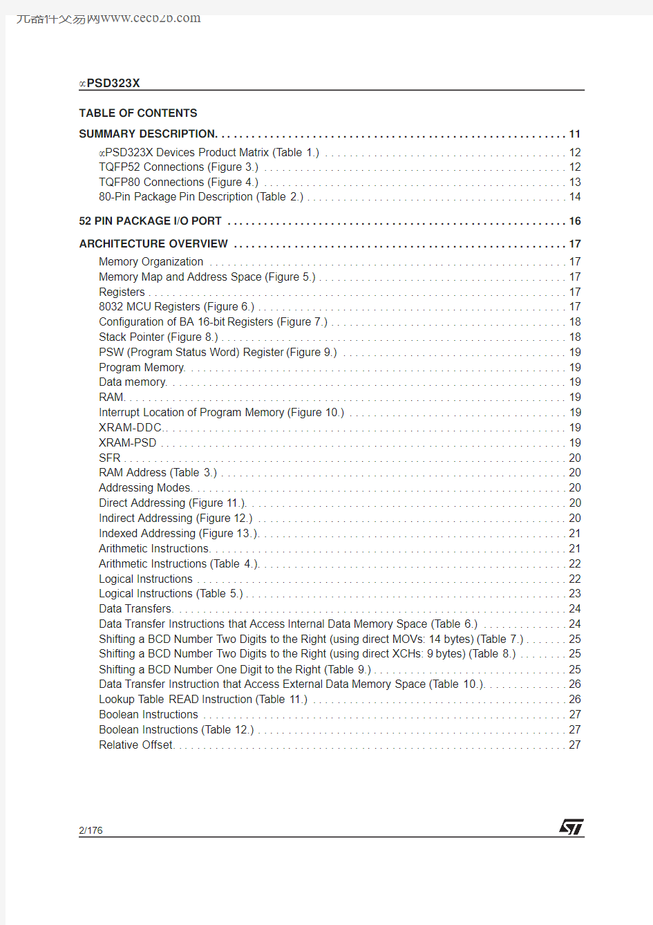
TABLE OF CONTENTS
SUMMARY DESCRIPTION (11)
μPSD323X Devices Product Matrix(Table1.) (12)
TQFP52Connections(Figure3.) (12)
TQFP80Connections(Figure4.) (13)
80-Pin Package Pin Description(Table2.) (14)
52PIN PACKAGE I/O PORT (16)
ARCHITECTURE OVERVIEW (17)
Memory Organization (17)
Memory Map and Address Space(Figure5.) (17)
Registers (17)
8032MCU Registers(Figure6.) (17)
Configuration of BA16-bit Registers(Figure7.) (18)
Stack Pointer(Figure8.) (18)
PSW(Program Status Word)Register(Figure9.) (19)
Program Memory (19)
Data memory (19)
RAM (19)
Interrupt Location of Program Memory(Figure10.) (19)
XRAM-DDC (19)
XRAM-PSD (19)
SFR (20)
RAM Address(Table3.) (20)
Addressing Modes (20)
Direct Addressing(Figure11.) (20)
Indirect Addressing(Figure12.) (20)
Indexed Addressing(Figure13.) (21)
Arithmetic Instructions (21)
Arithmetic Instructions(Table4.) (22)
Logical Instructions (22)
Logical Instructions(Table5.) (23)
Data Transfers (24)
Data Transfer Instructions that Access Internal Data Memory Space(Table6.) (24)
Shifting a BCD Number Two Digits to the Right(using direct MOVs:14bytes)(Table7.) (25)
Shifting a BCD Number Two Digits to the Right(using direct XCHs:9bytes)(Table8.) (25)
Shifting a BCD Number One Digit to the Right(Table9.) (25)
Data Transfer Instruction that Access External Data Memory Space(Table10.) (26)
Lookup Table READ Instruction(Table11.) (26)
Boolean Instructions (27)
Boolean Instructions(Table12.) (27)
Relative Offset (27)
2/176
元器件交易网https://www.doczj.com/doc/7b9473367.html,
μPSD323X
Jump Instructions (28)
Unconditional Jump Instructions(Table13.) (28)
Machine Cycles (29)
Conditional Jump Instructions (29)
State Sequence inμPSD323X Devices(Figure14.) (30)
μPSD3200HARDWARE DESCRIPTION (31)
μPSD323X Devices Functional Modules(Figure15.) (31)
MCU MODULE DISCRIPTION (32)
Special Function Registers (32)
SFR Memory Map(Table15.) (32)
List of all SFR(Table16.) (33)
PSD Module Register Address Offset(Table17.) (37)
INTERRUPT SYSTEM (39)
External Int0 (39)
Timer0and1Interrupts (39)
Timer2Interrupt (39)
I2C Interrupt (39)
External Int1 (39)
DDC Interrupt (39)
USB Interrupt (39)
USART Interrupt (40)
Interrupt System(Figure16.) (40)
SFR Register(Table18.) (41)
Interrupt Priority Structure (41)
Interrupts Enable Structure (41)
Priority Levels(Table19.) (41)
Description of the IE Bits(Table20.) (41)
Description of the IEA Bits(Table21.) (42)
Description of the IP Bits(Table22.) (42)
Description of the IPA Bits(Table23.) (42)
How Interrupts are Handled (43)
Vector Addresses(Table24.) (43)
POWER-SAVING MODE (44)
Idle Mode (44)
Power-Down Mode (44)
Power-Saving Mode Power Consumption(Table25.) (44)
Power Control Register (44)
Pin Status During Idle and Power-down Mode(Table26.) (44)
Description of the PCON Bits(Table27.) (44)
Idle Mode (44)
3/176
元器件交易网https://www.doczj.com/doc/7b9473367.html,
μPSD323X
I/O PORTS(MCU Module) (46)
I/O Port Functions(Table28.) (46)
P1SFS(91H)(Table29.) (46)
P3SFS(93H)(Table30.) (46)
P4SFS(94H)(Table31.) (46)
PORT Type and Description (47)
PORT Type and Description(Part1)(Figure17.) (47)
PORT Type and Description(Part2)(Figure18.) (48)
OSCILLATOR (49)
Oscillator(Figure19.) (49)
SUPERVISORY (49)
RESET Configuration(Figure20.) (49)
External Reset (50)
Low VDD Voltage Reset (50)
Watchdog Timer Overflow (50)
USB Reset (50)
WATCHDOG TIMER (51)
Watchdog Timer Key Register(WDKEY:0AEH)(Table32.) (51)
Description of the WDKEY Bits(Table33.) (51)
RESET Pulse Width(Figure21.) (52)
Watchdog Timer Clear Register(WDRST:0A6H)(Table34.) (52)
Description of the WDRST Bits(Table35.) (52)
TIMER/COUNTERS(TIMER0,TIMER1AND TIMER2) (53)
Timer0and Timer1 (53)
Control Register(TCON)(Table36.) (53)
Description of the TCON Bits(Table37.) (53)
TMOD Register(TMOD)(Table38.) (54)
Description of the TMOD Bits(Table39.) (54)
Timer/Counter Mode0:13-bit Counter(Figure22.) (55)
Timer/Counter Mode2:8-bit Auto-reload(Figure23.) (55)
Timer/Counter Mode3:Two8-bit Counters(Figure24.) (56)
Timer2 (56)
Timer/Counter2Control Register(T2CON)(Table40.) (57)
Description of the T2CON Bits(Table41.) (57)
Timer/Counter2Operating Modes(Table42.) (58)
Timer2in Capture Mode(Figure25.) (58)
Timer2in Auto-Reload Mode(Figure26.) (59)
4/176
元器件交易网https://www.doczj.com/doc/7b9473367.html,
μPSD323X
STANDARD SERIAL INTERFACE(UART) (60)
Multiprocessor Communications (60)
Serial Port Control Register (60)
Serial Port Control Register(SCON)(Table43.) (60)
Description of the SCON Bits(Table44.) (61)
Timer1-Generated Commonly Used Baud Rates(Table45.) (62)
Serial Port Mode0,Block Diagram(Figure27.) (65)
Serial Port Mode0,Waveforms(Figure28.) (66)
Serial Port Mode1,Block Diagram(Figure29.) (66)
Serial Port Mode1,Waveforms(Figure30.) (67)
Serial Port Mode2,Block Diagram(Figure31.) (67)
Serial Port Mode2,Waveforms(Figure32.) (68)
Serial Port Mode3,Block Diagram(Figure33.) (68)
Serial Port Mode3,Waveforms(Figure34.) (69)
ANALOG-TO-DIGITAL CONVERTOR(ADC) (70)
ADC Interrupt (70)
A/D Block Diagram(Figure35.) (70)
ADC SFR Memory Map(Table46.) (71)
Description of the ACON Bits(Table47.) (71)
ADC Clock Input(Table48.) (71)
PULSE WIDTH MODULATION(PWM) (72)
4-channel PWM unit(PWM0-3) (72)
Four-Channel8-bit PWM Block Diagram(Figure36.) (73)
PWM SFR Memory Map(Table49.) (74)
Programmable Period8-bit PWM (75)
Programmable PWM4Channel Block Diagram(Figure37.) (75)
PWM4Channel Operation (76)
PWM4With Programmable Pulse Width and Frequency(Figure38.) (76)
I2C INTERFACE (77)
Block Diagram of the I2C Bus Serial I/O(Figure39.) (77)
Serial Control Register(SxCON:S1CON,S2CON)(Table50.) (78)
Description of the SxCON Bits(Table51.) (78)
Selection of the Serial Clock Frequency SCL in Master Mode(Table52.) (78)
Serial Status Register(SxSTA:S1STA,S2STA) (79)
Data Shift Register(SxDAT:S1DAT,S2DAT) (79)
Serial Status Register(SxSTA)(Table53.) (79)
Description of the SxSTA Bits(Table54.) (79)
Data Shift Register(SxDAT:S1DAT,S2DAT)(Table55.) (79)
Address Register(SxADR:S1ADR,S2ADR) (80)
Address Register(SxADR)(Table56.) (80)
Start/Stop Hold Time Detection Register(S1SETUP,S2SETUP)(Table57.) (80)
System Cock of40MHz(Table58.) (80)
System Clock Setup Examples(Table59.) (80)
Programmer’s Guide for I2C and DDC2 (81)
5/176
元器件交易网https://www.doczj.com/doc/7b9473367.html,
μPSD323X
DDC INTERFACE (83)
DDC Interface Block Diagram(Figure40.) (83)
Special Function Register for the DDC Interface (84)
DDC SFR Memory Map(Table60.) (84)
Description of the DDCON Register Bits(Table61.) (85)
SWNEB Bit Function(Table62.) (86)
Host Type Detection (87)
Host Type Detection(Figure41.) (87)
DDC1Protocol (88)
Transmission Protocol in the DDC1Interface(Figure42.) (88)
DDC2B Protocol (89)
Conceptual Structure of the DDC Interface(Figure43.) (89)
USB HARDWARE (90)
USB related registers (90)
USB Address Register(UADR:0EEh)(Table63.) (90)
Description of the UADR Bits(Table64.) (90)
USB Interrupt Enable Register(UIEN:0E9h)(Table65.) (91)
Description of the UIEN Bits(Table66.) (91)
USB Interrupt Status Register(UISTA:0E8h)(Table67.) (91)
Description of the UISTA Bits(Table68.) (92)
USB Endpoint0Transmit Control Register(UCON0:0EAh)(Table69.) (93)
Description of the UCON0Bits(Table70.) (93)
USB Endpoint1(and2)Transmit Control Register(UCON1:0EBh)(Table71.) (94)
Description of the UCON1Bits(Table72.) (94)
USB Control Register(UCON2:0ECh)(Table73.) (95)
Description of the UCON2Bits(Table74.) (95)
USB Endpoint0Status Register(USTA:0EDh)(Table75.) (95)
Description of the USTA Bits(Table76.) (95)
USB Endpoint0Data Receive Register(UDR0:0EFh)(Table77.) (95)
USB Endpoint0Data Transmit Register(UDT0:0E7h)(Table78.) (95)
USB Endpoint1Data Transmit Register(UDT1:0E6h)(Table79.) (95)
USB SFR Memory Map(Table80.) (96)
Transceiver (97)
Low Speed Driver Signal Waveforms(Figure44.) (97)
Receiver Characteristics (98)
Differential Input Sensitivity Over Entire Common Mode Range(Figure45.) (98)
External USB Pull-Up Resistor (99)
USB Data Signal Timing and Voltage Levels(Figure46.) (99)
Receiver Jitter Tolerance(Figure47.) (99)
Differential to EOP Transition Skew and EOP Width(Figure48.) (100)
Differential Data Jitter(Figure49.) (100)
Transceiver DC Characteristics(Table81.) (101)
Transceiver AC Characteristics(Table82.) (101)
6/176
元器件交易网https://www.doczj.com/doc/7b9473367.html,
μPSD323X
PSD MODULE (102)
Functional Overview (102)
PSD MODULE Block Diagram(Figure50.) (103)
In-System Programming(ISP) (104)
Methods of Programming Different Functional Blocks of the PSD MODULE(Table83.) (104)
DEVELOPMENT SYSTEM (105)
PSDsoft Express Development Tool(Figure51.) (105)
PSD MODULE REGISTER DESCRIPTION AND ADDRESS OFFSET (106)
Register Address Offset(Table84.) (106)
PSD MODULE DETAILED OPERATION (107)
MEMORY BLOCKS (107)
Primary Flash Memory and Secondary Flash memory Description (107)
Memory Block Select Signals (107)
Instructions (108)
Instructions(Table85.) (109)
Power-down Instruction and Power-up Mode (110)
READ (110)
Status Bit(Table86.) (111)
Programming Flash Memory (112)
Data Polling Flowchart(Figure52.) (112)
Data Toggle Flowchart(Figure53.) (113)
Erasing Flash Memory (114)
Specific Features (115)
Sector Protection/Security Bit Definition–Flash Protection Register(Table87.) (115)
Sector Protection/Security Bit Definition–Secondary Flash Protection Register(Table88.) (115)
SRAM (116)
Sector Select and SRAM Select (116)
Priority Level of Memory and I/O Components in the PSD MODULE(Figure54.) (117)
VM Register(Table89.) (117)
Separate Space Mode(Figure55.) (118)
Combined Space Mode(Figure56.) (118)
Page Register (119)
Page Register(Figure57.) (119)
PLDs (120)
DPLD and CPLD Inputs(Table90.) (120)
The Turbo Bit in PSD MODULE (120)
PLD Diagram(Figure58.) (121)
Decode PLD(DPLD) (122)
DPLD Logic Array(Figure59.) (122)
Complex PLD(CPLD) (123)
Macrocell and I/O Port(Figure60.) (123)
Output Macrocell Port and Data Bit Assignments(Table91.) (124)
7/176
元器件交易网https://www.doczj.com/doc/7b9473367.html,
μPSD323X
Product Term Allocator (125)
CPLD Output Macrocell(Figure61.) (125)
Input Macrocells(IMC) (126)
Input Macrocell(Figure62.) (126)
I/O PORTS(PSD MODULE) (127)
General Port Architecture (127)
General I/O Port Architecture(Figure63.) (127)
Port Operating Modes (128)
MCU I/O Mode (128)
PLD I/O Mode (128)
Address Out Mode (128)
Peripheral I/O Mode (128)
JTAG In-System Programming(ISP) (128)
Peripheral I/O Mode(Figure64.) (129)
Port Operating Modes(Table92.) (129)
Port Operating Mode Settings(Table93.) (129)
I/O Port Latched Address Output Assignments(Table94.) (129)
Port Configuration Registers(PCR) (130)
Port Configuration Registers(PCR)(Table95.) (130)
Port Pin Direction Control,Output Enable P.T.Not Defined(Table96.) (130)
Port Pin Direction Control,Output Enable P.T.Defined(Table97.) (130)
Port Direction Assignment Example(Table98.) (130)
Port Data Registers (131)
Drive Register Pin Assignment(Table99.) (131)
Ports A and B–Functionality and Structure (132)
Port A and Port B Structure(Figure65.) (132)
Port C–Functionality and Structure (133)
Port C Structure(Figure66.) (133)
Port D–Functionality and Structure (134)
Port D Structure(Figure67.) (134)
External Chip Select (135)
Port D External Chip Select Signals(Figure68.) (135)
POWER MANAGEMENT (136)
APD Unit(Figure69.) (136)
Enable Power-down Flow Chart(Figure70.) (137)
Power-down Mode’s Effect on Ports(Table101.) (137)
PLD Power Management (138)
PSD Chip Select Input(CSI,PD2) (138)
Input Clock (138)
Input Control Signals (138)
Power Management Mode Registers PMMR01(Table102.) (138)
Power Management Mode Registers PMMR21(Table103.) (139)
APD Counter Operation(Table104.) (139)
8/176
元器件交易网https://www.doczj.com/doc/7b9473367.html,
μPSD323X
RESET TIMING AND DEVICE STATUS AT RESET (140)
Warm RESET (140)
I/O Pin,Register and PLD Status at RESET (140)
Reset of Flash Memory Erase and Program Cycles (140)
Reset(RESET)Timing(Figure71.) (140)
Status During Power-on RESET,Warm RESET and Power-down Mode(Table105.) (141)
PROGRAMMING IN-CIRCUIT USING THE JTAG SERIAL INTERFACE (142)
Standard JTAG Signals (142)
JTAG Port Signals(Table106.) (142)
JTAG Extensions (142)
Security and Flash memory Protection (142)
INITIAL DELIVERY STATE (142)
AC/DC PARAMETERS (143)
PLD ICC/Frequency Consumption(5V range)(Figure72.) (143)
PLD ICC/Frequency Consumption(3V range)(Figure73.) (143)
PSD MODULE Example,Typ.Power Calculation at V CC=5.0V(Turbo Mode Off)(Table107.).144
MAXIMUM RATING (145)
Absolute Maximum Ratings(Table108.) (145)
DC AND AC PARAMETERS (146)
Operating Conditions(5V Devices)(Table109.) (146)
Operating Conditions(3V Devices)(Table110.) (146)
AC Symbols for Timing(Table111.) (147)
Switching Waveforms–Key(Figure74.) (147)
DC Characteristics(5V Devices)(Table112.) (148)
DC Characteristics(3V Devices)(Table113.) (150)
External Program Memory READ Cycle(Figure75.) (152)
External Program Memory AC Characteristics(with the5V MCU Module)(Table114.) (152)
External Program Memory AC Characteristics(with the3V MCU Module)(Table115.) (153)
External Clock Drive(with the5V MCU Module)(Table116.) (153)
External Clock Drive(with the3V MCU Module)(Table117.) (153)
External Data Memory READ Cycle(Figure76.) (154)
External Data Memory WRITE Cycle(Figure77.) (154)
External Data Memory AC Characteristics(with the5V MCU Module)(Table118.) (155)
External Data Memory AC Characteristics(with the3V MCU Module)(Table119.) (156)
A/D Analog Specification(Table120.) (156)
Input to Output Disable/Enable(Figure78.) (157)
CPLD Combinatorial Timing(5V Devices)(Table121.) (157)
CPLD Combinatorial Timing(3V Devices)(Table122.) (157)
Synchronous Clock Mode Timing–PLD(Figure79.) (158)
CPLD Macrocell Synchronous Clock Mode Timing(5V Devices)(Table123.) (158)
CPLD Macrocell Synchronous Clock Mode Timing(3V Devices)(Table124.) (159)
Asynchronous RESET/Preset(Figure80.) (160)
9/176
元器件交易网https://www.doczj.com/doc/7b9473367.html,
μPSD323X
Asynchronous Clock Mode Timing(product term clock)(Figure81.) (160)
CPLD Macrocell Asynchronous Clock Mode Timing(5V Devices)(Table125.) (160)
CPLD Macrocell Asynchronous Clock Mode Timing(3V Devices)(Table126.) (161)
Input Macrocell Timing(product term clock)(Figure82.) (162)
Input Macrocell Timing(5V Devices)(Table127.) (162)
Input Macrocell Timing(3V Devices)(Table128.) (162)
Program,WRITE and Erase Times(5V Devices)(Table129.) (163)
Program,WRITE and Erase Times(3V Devices)(Table130.) (163)
Peripheral I/O READ Timing(Figure83.) (164)
Port A Peripheral Data Mode READ Timing(5V Devices)(Table131.) (164)
Port A Peripheral Data Mode READ Timing(3V Devices)(Table132.) (164)
Peripheral I/O WRITE Timing(Figure84.) (165)
Port A Peripheral Data Mode WRITE Timing(5V Devices)(Table133.) (165)
Port A Peripheral Data Mode WRITE Timing(3V Devices)(Table134.) (165)
Reset(RESET)Timing(Figure85.) (166)
Reset(RESET)Timing(5V Devices)(Table135.) (166)
Reset(RESET)Timing(3V Devices)(Table136.) (166)
V STBYON Definitions Timing(5V Devices)(Table137.) (166)
V STBYON Timing(3V Devices)(Table138.) (166)
ISC Timing(Figure86.) (167)
ISC Timing(5V Devices)(Table139.) (167)
ISC Timing(3V Devices)(Table140.) (168)
MCU Module AC Measurement I/O Waveform(Figure87.) (168)
PSD MODULE AC Float I/O Waveform(Figure88.) (168)
External Clock Cycle(Figure89.) (169)
Recommended Oscillator Circuits(Figure90.) (169)
PSD MODULE AC Measurement I/O Waveform(Figure91.) (169)
PSD MODULEAC Measurement Load Circuit(Figure92.) (169)
Capacitance(Table141.) (169)
PART NUMBERING (174)
PACKAGE MECHANICAL INFORMATION (170)
PART NUMBERING (174)
10/176
μPSD323X SUMMARY DESCRIPTION
s Dual bank Flash memories
–Concurrent operation,read from memory while erasing and writing the other.In-Appli-cation Programming(IAP)for remote updates –Large128KByte or256KByte main Flash memory for application code,operating sys-tems,or bit maps for graphic user interfaces –Large32KByte secondary Flash memory di-vided in small sectors.Eliminate external EE-PROM with software EEPROM emulation –Secondary Flash memory is large enough for sophisticated communication protocol(USB) during IAP while continuing critical system tasks
s Large SRAM with battery back-up option –8KByte SRAM for RTOS,high-level languag-es,communication buffers,and stacks
s Programmable Decode PLD for flexible address mapping of all memories
–Place individual Flash and SRAM sectors on any address boundary
–Built-in page register breaks restrictive8032 limit of64KByte address space
–Special register swaps Flash memory seg-ments between8032“program”space and “data”space for efficient In-Application Pro-gramming
s High-speed clock standard8032core(12-cycle)–40MHz operation at5V,24MHz at3.3V
–2UARTs with independent baud rate,three 16-bit Timer/Counters and two External Inter-rupts
s USB Interface(μPSD3234A-40only)
–Supports USB1.1Slow Mode(1.5Mbit/s)
–Control endpoint0and interrupt endpoints1 and2
s I2C interface for peripheral connections –Capable of master or slave operation
s5Pulse Width Modulator(PWM)channels –Four8-bit PWM units
–One8-bit PWM unit with programmable peri-od s4-channel,8-bit Analog-to-Digital Converter (ADC)with analog supply voltage(V REF)
s Standalone Display Data Channel(DDC)–For use in monitor,projector,and TV applica-tions
–Compliant with VESA standards DDC1and DDC2B
–Eliminate external DDC PROM
s Six I/O ports with up to50I/O pins
–Multifunction I/O:GPIO,DDC,I2C,PWM, PLD I/O,supervisor,and JTAG
–Eliminates need for external latches and logic
s3000gate PLD with16macrocells
–Create glue logic,state machines,delays, etc.
–Eliminate external PALs,PLDs,and74HCxx –Simple PSDsoft Express software...Free
s Supervisor functions
–Generates reset upon low voltage or watch-dog time-out.Eliminate external supervisor device
–RESET Input pin;Reset output via PLD
s In-System Programming(ISP)via JTAG –Program entire chip in10-25seconds with no involvement of8032
–Allows efficient manufacturing,easy product testing,and Just-In-Time inventory
–Eliminate sockets and pre-programmed parts –Program with FlashLINK TM cable and any PC s Content Security
–Programmable Security Bit blocks access of device programmers and readers
s Zero-Power Technology
–Memories and PLD automatically reach standby current between input changes
s Packages
–52-pin TQFP
–80-pin TQFP:allows access to8032address/ data/control signals for connecting to external peripherals
元器件交易网https://www.doczj.com/doc/7b9473367.html,
11/176
μPSD323X
12/176
Table 1.μPSD323X Devices Product Matrix
Figure 3.TQFP52Connections
Note: 1.Pull-up resistor required on pin 5(2k ?for 3V devices,7.5k ?for 5V devices)for all 52-pin devices,with or without USB function.
Part No.Main Flash (bit)Sec.
Flash
(bit)SRAM (bit)Macro -Cells I/O Pins PWM Ch.Timer
/Ctr
UART Ch.
I 2
C ADC Ch.DDC
USB
V CC
MHz Pins
uPSD 3234A-402M
256K
64K
16
41or
50
5
3
214yes yes 5V 40
52or
80
uPSD 3234BV-242M 256K 64K 165053214yes 3V 2480
uPSD 3233B-401M 256K 64K 16
41or 5053214yes 5V 40
52or 80uPSD 3233BV-24
1M 256K 64K 1641or 50
53214yes 3V 24
52or 80
39P1.5/ADC1 38P1.4/ADC0 37P1.3/TXD1 36P1.2/RXD1 35P1.1/T2X 34P1.0/T2 33V CC 32XTAL2 31XTAL1 30P3.7/SCL1 29P3.6/SDA1 28P3.5/T1 27P3.4/T0
PD1 PC7 PC6 PC5 USB– PC4 USB+ V CC GND PC3 PC2 PC1 PC0 1 2 3 4 5(1) 6 7 8 9 10 11 12 13
52 51 50 49 48 47 46 45 44 43 42 41 40P B 0
P B 1
P B 2
P B 3
P B 4
P B 5
V R E F
G N D
R E S E T
P B 6
P B 7
A D C 3
A D C 2
14
15
16
17
18
19
20
21
22
23
24
25
26
P 4.7/P W M 4 P 4.6/P W M 3 P 4.5/P W M 2 P 4.4/P W M 1 P 4.3/P W M 0 G N D P 4.2/D D C V S Y N C P 4.1/D D C S C L P 4.0/D D C S D A P 3.0/R X D P 3.1/T X D P 3.2/E X I N T 0 P 3.3/E X I N T 1AI05790C
元器件交易网https://www.doczj.com/doc/7b9473367.html,
13/176
μPSD323X
Figure 4.TQFP80Connections
Note:NC =Not Connected
1.Pull-up resistor required on pin 8(2k ?for 3V devices,7.5k ?for 5V devices)for all 82-pin devices,with or without USB function.
60P1.5/ADC1 59P1.4/ADC0 58P1.3/TXD1 57P2.3,A11 56P1.2/RXD1 55P2.2,A10 54P1.1/T2X 53P2.1,A9 52P1.0/T2 51P2.0,A8 50V CC 49XTAL2 48XTAL1 47P0.7,AD7 46P3.7/SCL1 45P0.6,AD6 44P3.6/SDA1 43P0.5,AD5 42P3.5/T1 41P0.4,AD4
PD2 P3.3/EXINT1 PD1 PD0,ALE PC7 PC6 PC5 USB- PC4 USB+ NC V CC GND PC3 PC2 PC1 NC P4.7/PWM4 P4.6/PWM3 PC01
2
3 4
5 6 7 8(1) 9 10 11 12 13 14 15 16 17
18 19
20
80 79 78 77 76 75 74 73 72 71 70 69 68 67 66 65 64 63 62 61P B 0
P 3.2/E X I N T 0
P B 1
P 3.1/T X D
P B 2
P 3.0/R X D
P B 3
P B 4
P B 5
N C
V R E F
G N D
R E S E T
P B 6
P B 7
R D ,C N T L 1
P 1.7/A D C 3
P S E N ,C N T L 2
W R ,C N T L 0
P 1.6/A D C 2
21
22
23
24
25
26
27
28
29
30
31
32
33
34
35
36
37
38
39
40
P A 7 P A 6 P 4.5/P W M 2 P A 5 P 4.4/P W M 1 P A 4 P 4.3/P W M 0 P A 3 G N D P 4.2/D C C V S Y N C P 4.1/D D C S C L P A 2 P 4.0/D D C S D A P A 1 P A 0 A D 0,P 0.0 A D 1,P 0.1 A D 2,P 0.2 A D 3,P 0.3 P 3.4/T 0AI05791B
元器件交易网https://www.doczj.com/doc/7b9473367.html,
μPSD323X
14/176
Table 2.80-Pin Package Pin Description
Port Pin Signal Name Pin No.In/Out Function
Basic
Alternate
P0.0AD036I/O External Bus
Multiplexed Address/Data bus A1/D1P0.1AD137I/O Multiplexed Address/Data bus A0/D0P0.2AD238I/O Multiplexed Address/Data bus A2/D2P0.3AD339I/O Multiplexed Address/Data bus A3/D3P0.4AD441I/O Multiplexed Address/Data bus A4/D4P0.5AD543I/O Multiplexed Address/Data bus A5/D5P0.6AD645I/O Multiplexed Address/Data bus A6/D6P0.7AD747I/O Multiplexed Address/Data bus A7/D7P1.0T252I/O General I/O port pin Timer 2Count input P1.1T2EX 54I/O General I/O port pin Timer 2Trigger input P1.2RxD256I/O General I/O port pin 2nd UART Receive P1.3TxD258I/O General I/O port pin 2nd UART Transmit P1.4ADC059I/O General I/O port pin ADC Channel 0input P1.5ADC160I/O General I/O port pin ADC Channel 1input P1.6ADC261I/O General I/O port pin ADC Channel 2input P1.7ADC364I/O General I/O port pin ADC Channel 3input
P2.0A851I/O External Bus,Address A8P2.1A953I/O External Bus,Address A9P2.2A1055I/O External Bus,Address A10P2.3A1157I/O External Bus,Address A11P3.0RxD175I/O General I/O port pin UART Receive P3.1TxD177I/O General I/O port pin UART Transmit
P3.2INTO 79I/O General I/O port pin Interrupt 0input /timer0gate control
P3.3INT12I/O General I/O port pin Interrupt 1input /timer1gate control P3.4T040I/O General I/O port pin Counter 0input P3.5T142I/O General I/O port pin Counter 1input P3.6SDA144I/O General I/O port pin I 2C Bus serial data I/O P3.7SCL146I/O General I/O port pin I 2C Bus clock I/O
P4.0SDA233I/O General I/O port pin I 2C serial data I/O for DDC interface
P4.1SCL231I/O General I/O port pin I 2C clock I/O for DDC interface P4.2
VSYNC
30
I/O
General I/O port pin
VSYNC input for DDC interface 元器件交易网https://www.doczj.com/doc/7b9473367.html,
15/176
μPSD323X
P4.3PWM027I/O General I/O port pin 8-bit Pulse Width Modulation output 0
P4.4PWM125I/O General I/O port pin 8-bit Pulse Width Modulation output 1
P4.5PWM223I/O General I/O port pin 8-bit Pulse Width Modulation output 2
P4.6PWM319I/O General I/O port pin 8-bit Pulse Width Modulation output 3
P4.7
PWM4
18
I/O
General I/O port pin
Programmable 8-bit Pulse Width modulation output 4
USB-8I/O
USB Pin Pull-up resistor required (2k ?for 3V devices,7.5k ?for 5V devices)for all devices,with or without USB https://www.doczj.com/doc/7b9473367.html,B+10I/O USB Pin
AVREF 70O Reference Voltage input for ADC RD_65O READ signal,external bus WR_62O WRITE signal,external bus PSEN_63O PSEN signal,external bus ALE 4O Address Latch signal,external bus RESET_68I Active low RESET input
XTAL148I Oscillator input pin for system clock XTAL2
49O Oscillator output pin for system clock PA035I/O General I/O port pin 1.PLD Macro-cell outputs 2.PLD inputs
https://www.doczj.com/doc/7b9473367.html,tched Address Out (A0-A7)
4.
Peripheral I/O Mode
PA134I/O General I/O port pin PA232I/O General I/O port pin PA328I/O General I/O port pin PA426I/O General I/O port pin PA524I/O General I/O port pin PA622I/O General I/O port pin PA7
21
I/O
General I/O port pin
Port Pin Signal Name Pin No.In/Out Function
Basic
Alternate
元器件交易网https://www.doczj.com/doc/7b9473367.html,
μPSD323X
16/176
52PIN PACKAGE I/O PORT
The 52-pin package members of the μPSD323X Devices have the same port pins as those of the 80-pin package except:
s Port 0(P0.0-P0.7,external address/data bus AD0-AD7)
s
Port 2(P2.0-P2.3,external address bus A8-A11)
s Port A (PA0-PA7)s Port D (PD2)
s
Bus control signal (RD,WR,PSEN,ALE)Pin 5requires a pull-up resistor (2k ?for 3V de-vices,7.5k ?for 5V devices)for all devices,with or without USB function.
PB080I/O General I/O port pin 1.PLD Macro-cell outputs 2.PLD inputs
https://www.doczj.com/doc/7b9473367.html,tched Address Out (A0-A7)
PB178I/O General I/O port pin PB276I/O General I/O port pin PB374I/O General I/O port pin PB473I/O General I/O port pin PB572I/O General I/O port pin PB667I/O General I/O port pin PB766
I/O General I/O port pin PC0TMS 20I JTAG pin 1.PLD Macro-cell outputs 2.PLD inputs
3.SRAM stand by voltage input (V STBY )
4.SRAM battery-on indicator (PC4)
5.JTAG pins are dedicated pins PC1TCK 16I JTAG pin
PC2V STBY 15I/O General I/O port pin PC3TSTA T 14I/O General I/O port pin PC4TERR 9I/O General I/O port pin PC5TDI 7I JTAG pin PC6TDO
6O JTAG pin
PC75
I/O General I/O port pin PD1CLKIN 3I/O General I/O port pin 1.PLD I/O
2.Clock input to PLD and APD PD2CSI
1I/O
General I/O port pin
1.PLD I/O
2.Chip select to PSD Module Vcc 12Vcc 50GND 13GND 29GND 69NC 11NC 17NC
71
Port Pin Signal Name
Pin No.In/Out Function
Basic
Alternate
元器件交易网https://www.doczj.com/doc/7b9473367.html,
17/176
μPSD323X
ARCHITECTURE OVERVIEW Memory Organization
The μPSD323X Devices’s standard 8032Core has separate 64KB address spaces for Program memory and Data Memory.Program memory is where the 8032executes instructions from.Data memory is used to hold data variables.Flash memory can be mapped in either program or data space.The Flash memory consists of two flash memory blocks:the main Flash (1or 2Mbit)and the Secondary Flash (256Kbit).Except during flash memory programming or update,Flash memory can only be read,not written to.A Page Register is used to access memory beyond the 64K bytes address space.Refer to the PSD Mod-ule for details on mapping of the Flash memory.The 8032core has two types of data memory (in-ternal and external)that can be read and written.The internal SRAM consists of 256bytes,and in-cludes the stack area.
The SFR (Special Function Registers)occupies the upper 128bytes of the internal SRAM,the reg-isters can be accessed by Direct addressing only.There are two separate blocks of external SRAM inside the μPSD323X Devices:one 256bytes block is assigned for DDC data storage.Another 8K bytes resides in the PSD Module that can be mapped to any address space defined by the user.
Figure 5.Memory Map and Address Space
Registers
The 8032has several registers;these are the Pro-gram Counter (PC),Accumulator (A),B Register (B),the Stack Pointer (SP),the Program Status Word (PSW),General purpose registers (R0to R7),and DPTR (Data Pointer register).
Figure 6.8032MCU Registers
AI06635
SECONDARY FLASH
FLASH
MAIN 32KB
128KB OR
256KB
FF
7F
FFFF
(DDC)
8KB
256B INT.RAM
EXT.RAM EXT.RAM
Addressing
Indirect Indirect
Direct or Addressing
Addressing
Direct SFR
Internal RAM Space (256Bytes)FF00
External RAM Space (MOVX)
Flash Memory Space
AI06636
Accumulator B Register Stack Pointer Program Counter Program Status Word General Purpose Register (Bank0-3)Data Pointer Register
PCH
DPTR(DPH)
A B SP
PCL PSW R0-R7
DPTR(DPL)
元器件交易网https://www.doczj.com/doc/7b9473367.html,
μPSD323X
18/176
Accumulator.The Accumulator is the 8-bit gen-eral purpose register,used for data operation such as transfer,temporary saving,and conditional tests.The Accumulator can be used as a 16-bit register with B Register as shown below.Figure 7.Configuration of BA 16-bit Registers
B Register.The B Register is the 8-bit general purpose register,used for an arithmetic operation such as multiply,division with Accumulator
Stack Pointer.The Stack Pointer Register is 8bits wide.It is incremented before data is stored during PUSH and CALL executions.While the stack may reside anywhere in on-chip RAM,the Stack Pointer is initialized to 07h after reset.This causes the stack to begin at location 08h.Figure 8.Stack Pointer
Program Counter.The Program Counter is a 16-bit wide which consists of two 8-bit registers,PCH and PCL.This counter indicates the address of the next instruction to be executed.In RESET state,the program counter has reset routine address (PCH:00h,PCL:00h).
Program Status Word.The Program Status Word (PSW)contains several bits that reflect the current state of the CPU and select Internal RAM (00h to 1Fh:Bank0to Bank3).The PSW is de-scribed in Figure 9,page 19.It contains the Carry flag,the Auxiliary carry flag,the Half Carry (for BCD operation),the general purpose flag,the Register bank select flags,the Overflow flag,and Parity flag.
[Carry Flag,CY].This flag stores any carry or not borrow from the ALU of CPU after an arithmetic operation and is also changed by the Shift Instruc-tion or Rotate Instruction.
[Auxiliary Carry Flag,AC].After operation,this is set when there is a carry from Bit 3of ALU or there is no borrow from Bit 4of ALU.
[Register Bank Select Flags,RS0,RS1].This flags select one of four bank(00~07H:bank0,08~0Fh:bank1,10~17h:bank2,17~1Fh:bank3)in Internal RAM.
[Overflow Flag,OV].This flag is set to ’1’when an overflow occurs as the result of an arithmetic oper-ation involving signs.An overflow occurs when the result of an addition or subtraction exceeds +127(7Fh)or -128(80h).The CLRV instruction clears the overflow flag.There is no set instruction.When the BIT instruction is executed,Bit 6of memory is copied to this flag.
[Parity Flag,P].This flag reflect on number of Ac-cumulator’s 1.If number of Accumulator’s 1is odd,P=0.otherwise P=1.Sum of adding Accumulator’s 1to P is always even.
R0~R7.General purpose 8-bit registers that are locked in the lower portion of internal data area.Data Pointer Register.Data Pointer Register is 16-bit wide which consists of two-8bit registers,DPH and DPL.This register is used as a data pointer for the data transmission with external data memory in the PSD Module.
AI06637
Two 8-bit Registers can be used as a ”BA”16-bit Registers
A
B
A
B
AI06638
SP (Stack Pointer)could be in 00h-FFh
SP
00h Stack Area (30h-FFh)
00h-FFh Hardware Fixed
Bit 15
Bit 0
Bit 8Bit 7
元器件交易网https://www.doczj.com/doc/7b9473367.html,
19/176
μPSD323X
Figure 9.PSW (Program Status Word)Register
Program Memory
The program memory consists of two Flash mem-ory:128KByte (or 256KByte)Main Flash and 32KByte of Secondary Flash.The Flash memory can be mapped to any address space as defined by the user in the PSDsoft Tool.It can also be mapped to Data memory space during Flash memory update or programming.
After reset,the CPU begins execution from loca-tion 0000h.As shown in Figure 10,each interrupt is assigned a fixed location in Program Memory.The interrupt causes the CPU to jump to that loca-tion,where it commences execution of the service routine.External Interrupt 0,for example,is as-signed to location 0003h.If External Interrupt 0is going to be used,its service routine must begin at location 0003h.If the interrupt is not going to be used,its service location is available as general purpose Pro-gram Memory.
The interrupt service locations are spaced at 8-byte intervals:0003h for External Interrupt 0,000Bh for Timer 0,0013h for External Interrupt 1,001Bh for Timer 1and so forth.If an interrupt ser-vice routine is short enough (as is often the case in control applications),it can reside entirely within that 8-byte interval.Longer service routines can use a jump instruction to skip over subsequent in-terrupt locations,if other interrupts are in use.Data memory
The internal data memory is divided into four phys-ically separated blocks:256bytes of internal RAM,128bytes of Special Function Registers (SFRs)areas,256bytes of external RAM (XRAM-DDC)and 8K bytes (XRAM-PSD)in the PSD Module.RAM
Four register banks,each 8registers wide,occupy locations 0through 31in the lower RAM area.Only one of these banks may be enabled at a time.The next 16bytes,locations 32through 47,con-tain 128directly addressable bit locations.The stack depth is only limited by the available internal RAM space of 256bytes.
Figure 10.Interrupt Location of Program Memory
XRAM-DDC
The 256bytes of XRAM-DDC used to support DDC interface is also available for system usage by indirect addressing through the address pointer DDCADR and data I/O buffer RAMBUF.The ad-dress pointer (DDCADR)is equipped with the post increment capability to facilitate the transfer of data in bulk (for details refer to DDC Interface part).However,it is also possible to address the RAM through MOVX command as normally used in the internal RAM extension of 80C51deriva-tives.XRAM-DDC FF00to FFFF is directly ad-dressable as external data memory locations FF00to FFFF via MOVX-DPTR instruction or via MOVX-Ri instruction.When XRAM-DDC is dis-abled,the address space FF00to FFFF can be as-signed to other resources.XRAM-PSD
The 8K bytes of XRAM-PSD resides in the PSD Module and can be mapped to any address space through the DPLD (Decoding PLD)as defined by the user in PSDsoft Development tool.The XRAM-PSD has a battery backup feature that allow the data to be retained in the event of a power lost.The battery is connected to the Port C PC2pin.This pin must be configured in PSDSoft to be bat-tery back-up.
AI06639
CY Reset Value 00h
Parity Flag Bit not assigned Overflow Flag
Register Bank Select Flags
(to select Bank0-3)Carry Flag
Auxillary Carry Flag General Purpose Flag
AC FO RS1RS0OV
P MSB LSB
PSW
AI06640
0000h
Reset
8Bytes
? ? ? ? ?
Interrupt Location
0003h
000Bh 0013h 008Bh ? ? ? ? 元器件交易网https://www.doczj.com/doc/7b9473367.html,
μPSD323X
20/176
SFR
The SFRs can only be addressed directly in the address range from 80h to FFh.Table 15,page 32gives an overview of the Special Function Regis-ters.Sixteen address in the SFRs space are both-byte and bit-addressable.The bit-addressable SFRs are those whose address ends in 0h and 8h.The bit addresses in this area are 80h to FFh.Table 3.RAM Address
Addressing Modes
The addressing modes in μPSD323X Devices in-struction set are as follows s Direct addressing
s Indirect addressing s Register addressing s Register-specific addressing s
Immediate constants addressing s
Indexed addressing
(1)Direct addressing.In a direct addressing the operand is specified by an 8-bit address field in the instruction.Only internal Data RAM and SFRs (80~FFH RAM)can be directly addressed.Example:
mov A,3EH ;A <-----RAM[3E]Figure 11.Direct Addressing
(2)Indirect addressing.In indirect addressing the instruction specifies a register which contains the address of the operand.Both internal and ex-ternal RAM can be indirectly addressed.The ad-dress register for 8-bit addresses can be R0or R1of the selected register bank,or the Stack Pointer.The address register for 16-bit addresses can only be the 16-bit “data pointer”register,DPTR.Example:
mov @R1,#40H ;[R1]<-----40H Figure 12.Indirect Addressing
Byte Address (in Hexadecimal)Byte Address (in Decimal)
↓↓FFh 25530h
48
msb Bit Address (Hex)lsb 2Fh 7F 7E 7D 7C 7B 7A 7978472Eh 7776757473727170462Dh 6F 6E 6D 6C 6B 6A 6968452Ch 6766656463626160442Bh 5F 5E 5D 5C 5B 5A 5958432Ah 57565554535251504229h 4F 4E 4D 4C 4B 4A 49484128h 47464544434241404027h 3F 3E 3D 3C 3B 3A 39383926h 37363534333231303825h 2F 2E 2D 2C 2B 2A 29283724h 27262524232221203623h 1F 1E 1D 1C 1B 1A 19183522h 17161514131211103421h 0F 0E 0D 0C 0B 0A 09083320h 07
06
05
04
03
02
01
00
321Fh Register Bank 3
3118h 2417h Register Bank 2
2310h 160Fh Register Bank 1
1508h 807h Register Bank 0
700h
AI06641
3Eh Program Memory
04A
AI06642R155h Program Memory
55
40h
元器件交易网https://www.doczj.com/doc/7b9473367.html,