PID控制教程(MATLAB官方出品)(本文是链接视频笔记)
举例说明
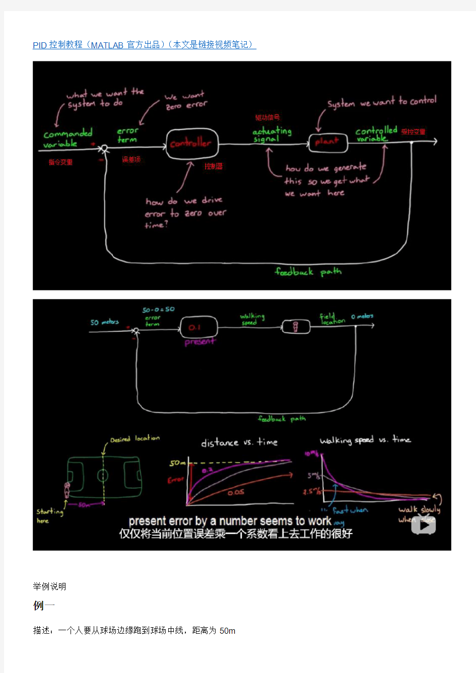
例一
描述:一个人要从球场边缘跑到球场中线,距离为50m
指令变量:50m;
驱动信号:行走的速度和方向;
设备:人
受控变量(输出):人所在位置(起始点为0m)
初始误差:50m-0m
控制器:大脑,控制以怎样的速度行走,这里把其值设为0.1
我们只需读取误差值,将其乘以0.1,就能得到行走速度。所以,起始时,行走速度为5m/s。
这种线性控制器,开始时,误差会下降得非常快,但是会随着目标距离的缩短而下降。当到达中线的时候,误差为零,从而输出一个零步行速度。在我们到达目的地是让我们停下来。如果想调整到达目的地的时间,可以调整比例系数。
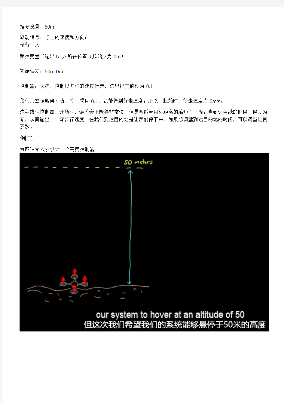
例二
为四轴无人机设计一个高度控制器
设备:无人机
系统的输出:海拔高度
系统输入:螺旋桨转速
当无人机升到海拔50m时,误差为零,螺旋桨转速为零,此时,无人机就会没有升力而掉落。紧接着无人机螺旋
桨速度又会增加,因为随着掉落,误差增大了。存在某一个螺旋桨转速,使得升力等于无人机的重力。第一次升力等于重力时,无人机并不会停下,因为还存在速度。只有速度为零,而且受力平衡,无人机才会悬停。
那么线性控制器将如何悬停无人机呢?这取决于系统的线性增益。假设,螺旋桨转速在100rpm时,能够使无人机悬停。如果线性增益为2,那么无人机将悬停在海拔0m。如果将增益调整为5,无人机将停在海拔30m,因为此时误差为20m。
无论如何增大线性增益,误差也不会消除。它只会随着增益增大变得越来越小。
这个简单的线性控制器不总是管用的,第二个例子最终会形成稳态误差。
那么我们如何调整增控制器避免产生稳态误差呢?
利用过去的信息,在控制器中加入一个积分路径与线性控制的路径并联。
一个积分器,能将不断输入其中的信号累加,得到实时更新的输入历史总和,因此它具有该系统过去状态的记忆。
或者说它追踪着系统发生过的一切。
如果无人机进入了低于预期高度的稳态,误差项此时非零。当一个非零的数被积分,积分器的输出将会增大,只要积分器存在误差,积分器输出就会一直变化。这个来自积分路径不断增大的数值,将会使螺旋桨速度增加,无人机将会继续升高。线性路径和积分路径的协同工作使得误差减小至零。
当无人机在预期50m悬停时,线性路径不作为,因为误差为零,但积分路径已经通过加加减减的反馈停留在100rpm
的输出,这是保证无人机悬停所需要的转速。并且,此时积分器的输出不会改变,因为在当前高度,积分器的输入是零。这个线性积分控制器就是我们想要的。这个控制器兼顾了当前和历史状态。
但是,当无人机达到50m时,所经历的路径并不是最优的。比如这种情况,恰好在无人机达到50m高度前,一个
有趣的情况将会发生,线性路径的输出基本是零,因为此时误差非常小,但由于无人机控制原理,当无人机达到这样的一个高度时,积分器可能已累加到高于100rpm的值,这将造成无人机持续爬升,在50m以下这是我们想要的,然而,为了抹去多余的螺旋桨转速,无人机不得不飞入到高于50m的高度,产生负误差。其在积分器中的累加会
减小积分器的输出,从而将螺旋桨转速降下来。这种飞过头的行为并不是我们预期的,幸运的是存在一个简单的办法解决这个问题。
那就是在控制器中加一条能够预测未来的路径,告诉我们无人机正在以多快的速度逼近目标。我们通过微分实现这个功能。
微分给出的是误差的变化率,它给出误差正以多块的速度增大或减小,比如,如果我们的无人机正在迅速上升,快速地接近目标高度,这意味着误差正在快速减小,这个正在减小的误差给出了负的变化率。也就是说微分路径将会输出一个负值。
这个输出将会加到控制器的输出中。因此会降低螺旋桨转速。我们的控制器使用变化的误差,发现了我们接近目标的速度过快,所以预先开始对螺旋桨减速,阻止了无人机超越预期高度。
我们就建立了PID控制器。
这是一个万能的控制器,他使用了当前的误差,历史误差以及对未来误差的预测,从而计算出恰当的驱动指令,这三部分按照一定比例组成了最终的控制器输出,作为设计者,你需要给出这三部分的权重,即调整各分支的增益项。
这叫做控制器的调节(tuning)。
如果控制器包含这三个分支的全部,则叫做PID控制器,如果有一个或多个分支的增益被设置为零,我们用剩下分支的首字母来称呼。比如PI控制器或P控制器。PID是反馈控制器的一种,但它十分容易理解和实施,它是一种
最简单的包含当前、过去和未来的控制器。这些基本特性,使它能够胜任大多数控制系统,尽管不是全部。
外文资料 Numerical Control One of the most fundamental concepts in the area of advanced manufacturing technol-ogies is Numerical Control(NC). Prior to the advent of NC, all machine tools were manually operated and controlled. Among the many limitations associated with manual control machine tools. Perhaps none is more prominent than the limitation of operator skills. With manual control, the quality of the product are directly related to and limited to the skills of the operator. Numerical Control represented the first major step away from human control of machine tools. Numerical Control means the control of machine tools and other manufacturing systems through the use of prerecorded, written symbolic instructions. Rather than operating a machine tool. For a machine tool to be numerically controlled, it must be interfaced with a device for accepting and decoding the programmed instructions, known as a reader. Numerical Control was developed to overcome the limitation of human operators, and it has done so. Numerical Control machines are more accurate than manually operated machines,they can produce parts more uniformly, they are faster, and the long-run tooling costs are lower. The development of NC led to the development of several other innovations in manufacturing technology: (1) Electrical discharge machining. (2) Laser cutting. (3) Electron beam welding. Numerical Control has also made machine tools more versatile than their manually operated predecessors. An NC machine tool can automatically produce a wide variety of parts, each involving an assortment of widely varied and comples machining processes. Numerical Control has allowed manufacturers to undertake the production of products that would not have been feasible from an economic perspective using manually controlled machine tools and processes.
附录 Abstract: Programmable controller in the field of industrial control applications, and PLC in the application process, to ensure normal operation should be noted that a series of questions, and give some reasonable suggestions. Key words: PLC Industrial Control Interference Wiring Ground Proposal Description Over the years, programmable logic controller (hereinafter referred to as PLC) from its production to the present, to achieve a connection to the storage logical leap of logic; its function from weak to strong, to achieve a logic control to digital control of progress; its applications from small to large, simple controls to achieve a single device to qualified motion control, process control and distributed control across the various tasks. PLC today in dealing with analog, digital computing, human-machine interface and the network have been a substantial increase in the capacity to become the mainstream of the field of control of industrial control equipment, in all walks of life playing an increasingly important role. ⅡPLC application areas Currently, PLC has been widely used in domestic and foreign steel, petroleum, chemical, power, building materials, machinery manufacturing, automobile, textile, transportation, environmental and cultural entertainment and other industries, the use of mainly divided into the following categories: 1. Binary logic control Replace traditional relay circuit, logic control, sequential control, can be used to control a single device can also be used for multi-cluster control and automation lines. Such as injection molding machine, printing machine, stapler machine, lathe, grinding machines, packaging lines, plating lines and so on. 2. Industrial Process Control In the industrial production process, there are some, such as temperature, pressure, flow, level and speed, the amount of continuous change (ie, analog), PLC using the appropriate A / D and D / A converter module, and a variety of control algorithm program to handle analog, complete closed-loop control. PID closed loop control system adjustment is generally used as a conditioning method was more. Process control in metallurgy, chemical industry, heat treatment, boiler control and so forth have a very wide range of applications 3. Motion Control PLC can be used in a circular motion or linear motion control. Generally use a dedicated motion control module, for example a stepper motor or servo motor driven single-axis or multi-axis position control module, used in a variety of machinery, machine tools, robots, elevators and other occasions. 4. Data Processing PLC with mathematics (including matrix operations, functions, operation, logic operation), data transfer, data conversion, sorting, look-up table, bit manipulation functions, you can complete the data collection, analysis and processing.Data
英文原文 Introductions to Control Systems Automatic control has played a vital role in the advancement of engineering and science. In addition to its extreme importance in space-vehicle, missile-guidance, and aircraft-piloting systems, etc, automatic control has become an important and integral part of modern manufacturing and industrial processes. For example, automatic control is essential in such industrial operations as controlling pressure, temperature, humidity, viscosity, and flow in the process industries; tooling, handling, and assembling mechanical parts in the manufacturing industries, among many others. Since advances in the theory and practice of automatic control provide means for attaining optimal performance of dynamic systems, improve the quality and lower the cost of production, expand the production rate, relieve the drudgery of many routine, repetitive manual operations etc, most engineers and scientists must now have a good understanding of this field. The first significant work in automatic control was James Watt’s centrifugal governor for the speed control of a steam engine in the eighteenth century. Other significant works in the early stages of development of control theory were due to Minorsky, Hazen, and Nyquist, among many others. In 1922 Minorsky worked on automatic controllers for steering ships and showed how stability could be determined by the differential equations describing the system. In 1934 Hazen, who introduced the term “ervomechanisms”for position control systems, discussed design of relay servomechanisms capable of closely following a changing input. During the decade of the 1940’s, frequency-response methods made it possible for engineers to design linear feedback control systems that satisfied performance requirements. From the end of the 1940’s to early 1950’s, the root-locus method in control system design was fully developed. The frequency-response and the root-locus methods, which are the
外文文献翻译 20106995 工机2班吴一凡 注:节选自Neural Network Introduction神经网络介绍,绪论。 History The history of artificial neural networks is filled with colorful, creative individuals from many different fields, many of whom struggled for decades to develop concepts that we now take for granted. This history has been documented by various authors. One particularly interesting book is Neurocomputing: Foundations of Research by John Anderson and Edward Rosenfeld. They have collected and edited a set of some 43 papers of special historical interest. Each paper is preceded by an introduction that puts the paper in historical perspective. Histories of some of the main neural network contributors are included at the beginning of various chapters throughout this text and will not be repeated here. However, it seems appropriate to give a brief overview, a sample of the major developments. At least two ingredients are necessary for the advancement of a technology: concept and implementation. First, one must have a concept, a way of thinking about a topic, some view of it that gives clarity not there before. This may involve a simple idea, or it may be more specific and include a mathematical description. To illustrate this point, consider the history of the heart. It was thought to be, at various times, the center of the soul or a source of heat. In the 17th century medical practitioners finally began to view the heart as a pump, and they designed experiments to study its pumping action. These experiments revolutionized our view of the circulatory system. Without the pump concept, an understanding of the heart was out of grasp. Concepts and their accompanying mathematics are not sufficient for a technology to mature unless there is some way to implement the system. For instance, the mathematics necessary for the reconstruction of images from computer-aided topography (CAT) scans was known many years before the availability of high-speed computers and efficient algorithms finally made it practical to implement a useful CAT system.
Microcomputer Systems Electronic systems are used for handing information in the most general sense; this information may be telephone conversation, instrument read or a company?s accounts, but in each case the same main type of operation are involved: the processing, storage and transmission of information. in conventional electronic design these operations are combined at the function level; for example a counter, whether electronic or mechanical, stores the current and increments it by one as required. A system such as an electronic clock which employs counters has its storage and processing capabilities spread throughout the system because each counter is able to store and process numbers. Present day microprocessor based systems depart from this conventional approach by separating the three functions of processing, storage, and transmission into different section of the system. This partitioning into three main functions was devised by V on Neumann during the 1940s, and was not conceived especially for microcomputers. Almost every computer ever made has been designed with this structure, and despite the enormous range in their physical forms, they have all been of essentially the same basic design. In a microprocessor based system the processing will be performed in the microprocessor itself. The storage will be by means of memory circuits and the communication of information into and out of the system will be by means of special input/output(I/O) circuits. It would be impossible to identify a particular piece of hardware which performed the counting in a microprocessor based clock because the time would be stored in the memory and incremented at regular intervals but the microprocessor. However, the software which defined the system?s behavior wou ld contain sections that performed as counters. The apparently rather abstract approach to the architecture of the microprocessor and its associated circuits allows it to be very flexible in use, since the system is defined almost entirely software. The design process is largely one of software engineering, and the similar problems of construction and maintenance which occur in conventional engineering are encountered when producing software. The figure1.1 illustrates how these three sections within a microcomputer are connected in terms of the communication of information within the machine. The system is controlled by the microprocessor which supervises the transfer of information between itself and the memory and input/output sections. The external connections relate to the rest (that is, the non-computer part) of the engineering system.
MATLAB模型预测控制工具箱函数 8.2 系统模型建立与转换函数 前面读者论坛了利用系统输入/输出数据进行系统模型辨识的有关函数及使用方法,为时行模型预测控制器的设计,需要对系统模型进行进一步的处理和转换。MATLAB的模型预测控制工具箱中提供了一系列函数完成多种模型转换和复杂系统模型的建立功能。 在模型预测控制工具箱中使用了两种专用的系统模型格式,即MPC状态空间模型和MPC传递函数模型。这两种模型格式分别是状态空间模型和传递函数模型在模型预测控制工具箱中的特殊表达形式。这种模型格式化可以同时支持连续和离散系统模型的表达,在MPC传递函数模型中还增加了对纯时延的支持。表8-2列出了模型预测控制工具箱的模型建立与转换函数。 表8-2 模型建立与转换函数 8.2.1 模型转换 在MATLAB模型预测工具箱中支持多种系统模型格式。这些模型格式包括: ①通用状态空间模型; ②通用传递函数模型; ③MPC阶跃响应模型; ④MPC状态空间模型;
⑤ MPC 传递函数模型。 在上述5种模型格式中,前两种模型格式是MATLAB 通用的模型格式,在其他控制类工具箱中,如控制系统工具箱、鲁棒控制工具等都予以支持;而后三种模型格式化则是模型预测控制工具箱特有的。其中,MPC 状态空间模型和MPC 传递函数模型是通用的状态空间模型和传递函数模型在模型预测控制工具箱中采用的增广格式。模型预测控制工具箱提供了若干函数,用于完成上述模型格式间的转换功能。下面对这些函数的用法加以介绍。 1.通用状态空间模型与MPC 状态空间模型之间的转换 MPC 状态空间模型在通用状态空间模型的基础上增加了对系统输入/输出扰动和采样周期的描述信息,函数ss2mod ()和mod2ss ()用于实现这两种模型格式之间的转换。 1)通用状态空间模型转换为MPC 状态空间模型函数ss2mod () 该函数的调用格式为 pmod= ss2mod (A,B,C,D) pmod = ss2mod (A,B,C,D,minfo) pmod = ss2mod (A,B,C,D,minfo,x0,u0,y0,f0) 式中,A, B, C, D 为通用状态空间矩阵; minfo 为构成MPC 状态空间模型的其他描述信息,为7个元素的向量,各元素分别定义为: ◆ minfo(1)=dt ,系统采样周期,默认值为1; ◆ minfo(2)=n ,系统阶次,默认值为系统矩阵A 的阶次; ◆ minfo(3)=nu ,受控输入的个数,默认值为系统输入的维数; ◆ minfo(4)=nd ,测量扰的数目,默认值为0; ◆ minfo(5)=nw ,未测量扰动的数目,默认值为0; ◆ minfo(6)=nym ,测量输出的数目,默认值系统输出的维数; ◆ minfo(7)=nyu ,未测量输出的数目,默认值为0; 注:如果在输入参数中没有指定m i n f o ,则取默认值。 x0, u0, y0, f0为线性化条件,默认值均为0; pmod 为系统的MPC 状态空间模型格式。 例8-5 将如下以传递函数表示的系统模型转换为MPC 状态空间模型。 1 2213)(232+++++=s s s s s s G 解:MATLAB 命令如下:
应用于现场总线系统的卡尔曼滤波 -有延迟信号的速率控制系统 R. Pizá, J. Salt, A. Cuenca, V. Casanova 巴伦西亚技术大学,西班牙 {rpiza,julian,acuenca,vcasanov}@isa.upv.es 摘要:网络控制系统设备(控制器,传感器和执行器)共享一个共同的通信介质。由于通信介质会受到外部的干扰,所以这些设备通过共享的通信介质时会被随意地延迟传输。带宽传输能力也是有限的,这也可以随意地限制我们从控制回路中获得采样周期。 我们可以依据高速质的采样周期来减少信号的延迟并减少一些带宽。通常这个解决方案能显著的影响系统的性能。这是因为采样周期的高速质,闭环反应能力将会下降。本文提出了一个建议,来解决这些类型的问题。用卡尔曼滤波器,采用多速率过滤器来减少传输的要求。这最终的目标是建立一个系统,并使它尽可能的接近于一个单一的速率系统,从而得到一个起始点和系统参考。 在这项工作中,我们的多速率建模方法认为,要在有Profibus-DP和起重机三维平台的硬件环境下才能实现实验结果的成功。我们在检测控制技术方面有些实验。其中一些实验表明,在直接控制起重机的情况下,没有Profibus-DP总线控制,网络将无法避免一些信号的延迟和丢失。其它的一些实验表面在整个硬件平台中,使用起重机并有现场总线时,网络可以避免信号的延迟和丢失。 一、导言 控制系统采用共享通信介质是由于以下的几个原因。其中一个原因是,需要在硬件平台减少电缆。另外一个原因是,同样的信息设备,要能增加多输入多输出系统或更多可能性的配置,并让配置更加容易,还能够创造更复杂的系统。 几种控制应用中需要共享的通信介质有[ 6]:遥控操作,监控和控制系统。这就是通过共享的网络而诞生的网络控制系统(新的系统)。一般来说,该网络包括大量线路的减少,因此,体现了较高的维护灵活性和较低的应用成本[ 15]。由于布线限制了大小(如航空,生产汽车)或空间分布的限制(如化工厂),让成本更低和运行更加优化简单,用上述的解决办法是可取的[ 4],[ 5]。
神经网络预测控制综述 摘要:近年来,神经网络预测控制在工业过程控制中不仅得到广泛的应用,而且其理论研究也取得了很大进展。对当前各种神经刚络预测控制方法的现状及其工业应用进行了较深入地分析,并对其存在的问题和今后可能的发展趋势作了进一步探讨。 关键词:神经网络;预测控制:非线性系统;工业过程控制 Abstract: In recent years, neural network predictive control has not only been widely used in industrial process control, but also has made great progress in theoretical research. The current status of various neural network prediction control methods and their industrial applications are analyzed in depth, and the existing question and possible future development trends are further discussed. Keywords: neural network; predictive control: nonlinear system; industrial process control
20世纪70年代以来,人们从工业过程的特点出发,寻找对模型精度要去不高而同样能实现高质量控制性能的方法,预测控制就是在这种背景下发展起的[1]。预测控制技术最初山Richalet和Cutler提出[2],具有多步预测、滚动优化、反馈校正等机理,因此能够克服过程模型的不确定性,体现出优良的控制性能,在工业过程控制中取得了成功的应用。如Shell公司、Honeywell公司、Centum 公司,都在它们的分布式控制系统DCS上装备了商业化的预测控制软件包.并广泛地将其应用于石油、化工、冶金等工业过程中[3]。但是,预测函数控制是以被控对象的基函数的输出响应可以叠加为前提的,因而只适用于线性动态系统控制。对于实际中大量的复杂的非线性工业过程。不能取得理想的控制效果。而神经网络具有分布存储、并行处理、联想记忆、自组织和自学习等功能,以神经元组成的神经网络可以逼近任意的:线性系统。使控制系统具有智能化、鲁棒性和适应性,能处理高维数、非线性、干扰强、难建模的复杂工业过程。因此,将神经网络应用于预测控制,既是实际应用的需要,同时也为预测控制理论的发展开辟了广阔的前景。本文对基于神经网络的预测控制的研究现状进行总结,并展望未来的发展趋势。 l神经网络预测控制的基本算法的发展[4] 实际中的控制对象都带有一定的菲线性,大多数具有弱非线性的对象可用线性化模型近似,并应用已有的线性控制理论的研究成果来获得较好的控制效果。而对具有强非线性的系统的控制则一直是控制界研究的热点和难点。 就预测控制的基本原理而言,只要从被控对象能够抽取出满足要求的预测模型,它便可以应用于任何类型的系统,包括线性和非线性系统。 由于神经网络理论在求解非线性方面的巨大优势,很快被应用于非线性预测控制中。其主要设计思想是:利用一个或多个神经刚络,对非线性系统的过程信息进行前向多步预测,然后通过优化一个含有这些预测信息的多步优化目标函数,获得非线性预测控制律。在实际应用与理论研究中形成了许多不同的算法。如神经网络的内模控制、神经网络的增量型模型算法控制等,近来一些学者对有约束神经网络的预测控制也作了相应的研究。文献[5]设计了多层前馈神经网络,使控制律离线求解。文献[6]采用两个网络进行预测,但结构复杂,距离实际应用还有一定的距离,文献[7]利用递阶遗传算法,经训练得出离线神经网络模型.经多步预测得出对象的预测模型,给出了具有时延的非线性系统的优化预测控制。将神经网络用于GPC的研究成果有利用Tank.Hopfield网络处理GPC矩阵求逆的算法,基于神经网络误差修正的GPC算法、利用小脑模型进行提前计算的GPC 算法、基于GPC的对角递归神经网络控制方法以及用神经网络处理约束情形的预
PID controller A proportional–integral–derivative controller (PID controller) is a generic .control loop feedback mechanism widely used in industrial control systems. A PID controller attempts to correct the error between a measured process variable and a desired setpoint by calculating and then outputting a corrective action that can adjust the process accordingly. The PID controller calculation (algorithm) involves three separate parameters; the Proportional, the Integral and Derivative values. The Proportional value determines the reaction to the current error, the Integral determines the reaction based on the sum of recent errors and the Derivative determines the reaction to the rate at which the error has been changing. The weightedsum of these three actions is used to adjust the process via a control element such as the position of a control valve or the power supply of a heating element. By "tuning" the three constants in the PID controller algorithm the PID can provide control action designed for specific process requirements. The response of the controller can be described in terms of the responsiveness of the controller to an error, the degree to which the controller overshoots the setpoint and the degree of system oscillation. Some applications may require using only one or two modes to provide the appropriate system control. This is achieved by setting the gain of undesired control outputs to zero. A PID controller will be called a PI, PD, P or I controller in the absence of the respective control actions. PI controllers are particularly common, since derivative action is very sensitive to measurement noise, and the absence of an integral value may prevent the system from reaching its target value due to the control action. 1.Control loop basics A familiar example of a control loop is the action taken to keep one's shower water at the ideal temperature, which typically involves the mixing of two process streams, cold and hot water. The person feels the water to estimate its temperature. Based on this measurement they perform a control action: use the cold water tap to adjust the process. The person would repeat this input-output control loop, adjusting the hot water flow until the process temperature stabilized at the desired value. Feeling the water temperature is taking a measurement of the process value or process variable (PV). The desired temperature is called the setpoint (SP). The output from the controller and input to the process (the tap position) is called the manipulated variable (MV). The difference between the measurement and the setpoint is the error (e), too hot or too cold and by how much. As a controller, one decides roughly how much to change the tap position (MV) after one determines the temperature (PV), and therefore the error. This first estimate is the equivalent of the proportional action of a PID controller. The integral action of a PID