管箱与托架板间沿四周垫以5mm厚的石棉板两层,图示5mm为受压后厚度。石棉板用户自理。
Two layers of asbestos plate in 5mm thickness shall be laid between tube tank and bracket 空气预热器各部分焊缝应保障其强度和密封,安装完毕后应进行密封性试验,漏风处应焊补密封。Intensity and seal of all welds in air preheater shall be guaranteed. Seal test shall be d 防磨短管本图未示出,与管子连接见节点图。
Abrasion-resist stub tube is not indicated in this drawing, which shall be connected with 序号19~26的尺寸工地上按具体情形而定。
Dimensions of S.Nos.19~26 shall be subject to actual condition at site.
管箱的吊装孔在安装就位后焊没。
The hanging hole of tube tank shall be welded-on after the completion of erection.
烟气连通箱护板内侧和防磨短管进口处敷耐火塑料,材料用户自理。
Plastic refractroy material shall be laid in inside casing of flue gas communicating tank 除注明焊缝外,型钢之间及型钢与钢板之间角焊缝均以5mm焊高连续密封焊,对接处对接焊。
Except the specified welds, fillet welds between shape steels and between shape steel and 空气预热器 Air preheater
空气预热器管箱 Tube tank of air preheater
上级两侧管箱 Upper tube tank at both sides
上级中间管箱 Upper tube tank at middle
中级两侧管箱 Upper tube tank at both sides
中级中间管箱 Medium tube tank at middle
下级两侧管箱 Lower tube tank at both sides
下级中间管箱 Lower tube tank at middle
座架及连通箱 Seat bracket and communicating tank
上部座架 Upper seat bracket
中部座架 Middle seat bracket
下部座架 Lower seat bracket
斜连通箱 Oblique communicating tank
中连通箱 Middle communicating tank
烟气连通箱 Flue gas communicating tank
上部侧护板 Upper side casing
中部侧护板 Middle side casing
下部侧护板 Lower side casing
密封件及连接件 Seal parts and connecting tube
管箱膨胀接头 Expansion joint of tube tank
连通箱胀缩接头 Expansion joint of communicating tank
胀缩接头 L=80m Expansion joint L=80m
密封钢板 L=40m Seal plate L=40m
槽钢[14a L=150 Channel steel [14a L=150
按总长供货,每段≥5m Supply per total length, and each sec. shall be no less than 5m.
正反各一 Each at Face/Back
装配件 Assembly
石棉板δ5 Asbestos plate δ5
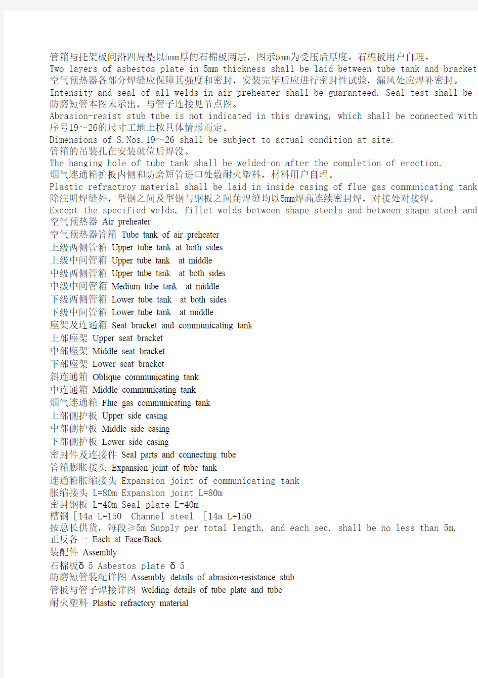
防磨短管装配详图 Assembly details of abrasion-resistance stub
管板与管子焊接详图 Welding details of tube plate and tube
耐火塑料 Plastic refractory material
边缘管孔中心线 Center line of tube hole at edge
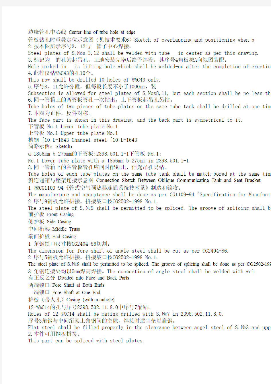
管板钻孔时重叠定位示意图(见技术要求6)Sketch of overlapping and positioning when b
2.按本图所示序号3、12与 管子中心焊接。
Steel plates of S.Nos.3,12 shall be welded with tube in center as per this drawing.
3.标记为 的孔为起吊孔,工地安装完毕后给予焊没,其序号4角板按A向视图装配。
Hole marked in is lifting hole which shall be welded-on after the completion of erection 4.此排仅钻%%C43的孔10个。
This row shall be drilled 10 holes of %%C43 only.
5.序号8、11允许分段,但每段长度不小于1000mm,装
Subsection is allowed for steel plates of S.Nos8,11, but each section shall be no less tha 6.同一管箱上的两管板管孔一次钻出,上下管板起吊孔另钻。
Tube holes of two pieces of tube plates on the same tube tank shall be drilled at one time 7.本图为正件,反件对称。
The face part is shown in this drawing, and the back part is symmetrical to it.
下管板 No.1 Lower tube plate No.1
上管板 No.1 Upper tube plate No.1
槽钢 [10 L=1643 Channel steel [10 L=1643
简略示例:Sketch:
a=1856mm b=275mm的下管板:2398.501.1-1下管板 No.1:
No.1 Lower tube plate with a=1856mm b=275mm in 2398.501.1-1
3.同一管箱上的各管板管孔应同时配钻出,但起吊孔另钻。
Tube holes of each tube plates on the same tube tank shall be match-bored at the same time 斜连通箱与座架连接示意图 Connection Sketch Between Oblique Communicating Tank and Seat Bracket
1 按CG1109-94《管式空气预热器连通系统技术条》制造和验收。
The manufacture and acceptance shall be done as per CG1109-94 "Specification for Manufactu 2 序号9钢板允许拼接,拼接坡口按CG2502-1998 No.1。
The steel plate of S.№9 shall be permitted to be spliced. The groove of splicing shall be 前护板 Front Casing
侧护板 Side Casing
中间桁架 Middle Truss
端面护板 End Casing
1 角钢锁口尺寸按CG2404-86切割。
The dimension for fore shaft of angle steel shall be cut as per CG2404-86.
2 序号5钢板允许拼接,拼接坡口按CG2502-1998 No.1。
The steel plate of S.№9 shall be permitted to be spliced. The groove of splicing shall be done as per CG2502-199 3 角钢连接处均以5mm焊高焊接。The connection of angle steel shall be welded with wel
有正反之分 Divided into Face and Back Parts
两端锁口 Fore Shaft at Both Ends
一端锁口 Fore Shaft at One End
护板(带人孔)Casing (with manhole)
12-%%C14的孔与序号2398.502.11.8.0中序号7配钻。
Holes of 12-%%C14 shall be mating drilled with S.№7 in 2398.502.11.8.0.
序号3角钢与中间绗架上角钢间的空隙,焊接时适当垫以扁钢。
Flat steel shall be filled properly in the clearance between angel steel of S.№3 and uppe 2.本件可用钢板拼接。
This part can be spliced with steel plates.
人孔装置480X340 Manhole Device 480X340
未注明型钢连接以 焊接。
Connection of shape steel not indicated shall be welded as per .
允许拼接,拼接焊缝按CG2502-1998No.1进行。
Splicing shall be permitted, and splicing welds shall be done as per CG2502-1998 No.1.
3.角钢与槽钢锁口尺寸按CG2408-86加工。
Dimension of fore shaft between angle steel and channel steel shall be done as per CG2408-4.槽钢与槽钢锁口尺寸按CG2407-86加工。
Dimension of fore shaft between channel steel shall be done as per CG2407-86.
直角胀缩接头 Rignt-angle Expansion Joint
1.序号1,3,4,5可分段出厂,每段不小于1m。
S.№1,3,4 and S.№5 can be delivered in sections, and each section shall not be less than 2.序号1,3,4,5包括安装余量。
S.№1,3,4 and S.№5 include erection allowances.
按中径展开长度=149mm。
The developed length as per pitch diameter is 149mm.
按图切割;切割面。
Cutting shall be done as per this drawing, and cutting surface is .
凡图中未注出而又有可能影响气密性的地方现场封焊,以保证密封。
All those not indicated but key to the air tightness shall be close welded to ensure the s 护板与护板的连接参照C-C、D-D、 B-B。
As for the connection of casing, please refer to C-C, D-D and B-B.
护板与护板之间的连接,除注明外,所有连接处均按K=4的角焊缝焊接。
Except for those indicated, the connection of casing shall be welded with fillet welds of 序号26本图未示出,作为现场密封用。
S.№26 not indicated in this drawing shall be used for sealing at site.
本图各安装件现场安装时允许修割,但必须保证密封和连接。
All erection parts in this drawing shall be permitted to be cut during the erection at sit 灰斗 Hopper
放灰装置 Ash Discharge Device
and bracket plates all around. 5mm indicated in drawing is the compressed thickness,an
风处应焊补密封。
eal test shall be done after the completion of erection and repair and seal welding shall be done fo be connected with tube as per Node Dra..
f erection.
communicating tank and inlet of abrasion-resist stub tube, and the material shall be supplied by cli 处对接焊。
en shape steel and steel plate shall receive continuous seal welding with reinforcement of 5mm, and less than 5m.
hen boring on tube plate(Refer to Specification 6)
this drawing.
pletion of erection at site, and angle plate of S.No4 shall be assembled as per Section A.
hall be no less than 1000mm,and gap of 2~4mm shall be reserved between each shall be drilled separa drilled at one time, and the lifting hole of upper and lower tube plate shall be drilled separately.
ed at the same time, but the lifting hole shall be bored separately.
and Seat Bracket
or Manufacture of Communicating System of Air Preheater".
f splicin
g shall be done as per CG2502-1998 №1.
one as per CG2502-1998 №1.
h weld height of 5mm.
l of S.№3 and upper angle steel of middle truss.
98 No.1.
done as per CG2408-86.
l not be less than 1m.
ded to ensure the sealing.
th fillet welds of K=4.
the erection at site. Sealing connection must be ensured.
ss,and the asbestos plate shall be supplied by client himself. ng shall be done for leakage area.
be supplied by client himself.
cement of 5mm, and the butting place shall receive butt welding.
illed separately. drilled separately.