
Engineering Structures29(2007)2503–2513
https://www.doczj.com/doc/ab9325786.html,/locate/engstruct
Optimum lead–rubber isolation bearings for near-fault motions
R.S.Jangid
Department of Civil Engineering,Indian Institute of Technology Bombay,Powai,Mumbai–400076,India
Received29May2006;received in revised form23October2006;accepted8December2006
Available online12February2007
Abstract
Analytical seismic response of multi-storey buildings isolated by lead–rubber bearings(LRB)is investigated under near-fault motions.The superstructure is idealized as a linear shear type?exible building.The force–deformation behaviour of the LRB is modelled as bilinear with viscous damping.The governing equations of motion of the isolated structural system are derived and the response of the system to normal component of six recorded near-fault motions is evaluated by step-by-step numerical method.The variation of top?oor absolute acceleration and bearing displacement of the isolated building is plotted under different system parameters such as superstructure?exibility,isolation period and bearing yield strength.The comparison of results indicated that for low bearing yield strength there is signi?cant displacement in the bearing under near-fault motions.In addition,there also exists a particular value of the yield strength of the LRB for which the top?oor absolute acceleration of the building attains the minimum value.Further,the optimum bearing yield strength is derived for different system parameters under near-fault motions.The criteria selected for optimality are the minimization of both the top?oor acceleration and the bearing displacement.The optimum yield strength of the LRB is found to be in the range of10%–15%of the total weight of the building under near-fault motions.In addition,the response of bridge seismically isolated by the LRB is also investigated and found that there exists a particular value of the bearing yield strength for which the pier base shear and deck acceleration attain the minimum value under near-fault motions.
c 2006Elsevier Ltd.All rights reserved.
Keywords:Base isolation;Earthquake;Near-fault motion;Lead–rubber bearings;Bearing yield strength;Superstructure?exibility;Optimum parameters
1.Introduction
Seismic isolation is an old design idea,proposing the decoupling of a structure or part of it,or even of equipment placed in the structure,from the damaging effects of ground accelerations.One of the goals of seismic isolation is to shift the fundamental frequency of a structure away from the dominant frequencies of earthquake ground motion and the fundamental frequency of the?xed base superstructure.The other purpose of an isolation system is to provide an additional means of energy dissipation,thereby reducing the transmitted acceleration into the superstructure.This innovative design approach aims mainly at the isolation of a structure from the supporting ground,generally in the horizontal direction,in order to reduce the transmission of the earthquake motion to the structure.Thus,base isolation essentially decouples the structure from the ground during earthquake excitation.
A variety of isolation devices including elastomeric bearings (with and without lead core),frictional/sliding bearings and E-mail address:rsjangid@civil.iitb.ac.in.roller bearings have been developed and used practically for aseismic design of buildings during the last20years[1,2]. Among the various base isolation systems,the lead–rubber bearings(LRB)had been used extensively in New Zealand, Japan and United States.The LR
B consists of alternate layers of rubber and steel plates with one or more lead plugs that are inserted into the holes.The lead core deforms in shear providing the bilinear response(i.e.adds hysteretic damping in the isolated structure)and also provides the initial rigidity against minor earthquakes and strong winds[3].The?rst building isolated by the LRB was the William Clayton building in Wellington,New Zealand completed in1981and followed by other buildings in several countries.The buildings isolated with LRB performed very well during the1994Northridge and 1995Kobe earthquakes con?rming the suitability of LRB as a base isolator[4–6].
Several seismologists have suggested that base-isolated buildings are vulnerable to large pulse-like ground motions generated at near-fault locations[7,8].The base-isolated buildings might perform poorly because of large isolator
0141-0296/$-see front matter c 2006Elsevier Ltd.All rights reserved. doi:10.1016/j.engstruct.2006.12.010
2504R.S.Jangid/Engineering Structures29(2007)
2503–2513
(a)Flexible superstructure.(b)Force–deformation of LRB.
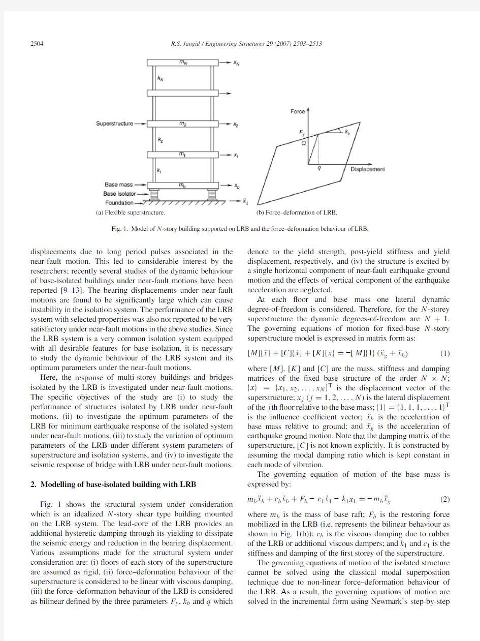
Fig.1.Model of N-story building supported on LRB and the force–deformation behaviour of LRB.
displacements due to long period pulses associated in the near-fault motion.This led to considerable interest by the researchers;recently several studies of the dynamic behaviour of base-isolated buildings under near-fault motions have been reported[9–13].The bearing displacements under near-fault motions are found to be signi?cantly large which can cause instability in the isolation system.The performance of the LRB system with selected properties was also not reported to be very satisfactory under near-fault motions in the above studies.Since the LRB system is a very common isolation system equipped with all desirable features for base isolation,it is necessary to study the dynamic behaviour of the LRB system and its optimum parameters under the near-fault motions.
Here,the response of multi-storey buildings and bridges isolated by the LRB is investigated under near-fault motions. The speci?c objectives of the study are(i)to study the performance of structures isolated by LRB under near-fault motions,(ii)to investigate the optimum parameters of the LRB for minimum earthquake response of the isolated system under near-fault motions,(iii)to study the variation of optimum parameters of the LRB under different system parameters of superstructure and isolation systems,and(iv)to investigate the seismic response of bridge with LRB under near-fault motions.
2.Modelling of base-isolated building with LRB
Fig.1shows the structural system under consideration which is an idealized N-story shear type building mounted on the LRB system.The lead-core of the LRB provides an additional hysteretic damping through its yielding to dissipate the seismic energy and reduction in the bearing displacement. Various assumptions made for the structural system under consideration are:(i)?oors of each story of the superstructure are assumed as rigid,(ii)force–deformation behaviour of the superstructure is considered to be linear with viscous damping, (iii)the force–deformation behaviour of the LRB is considered as bilinear de?ned by the three parameters F y,k b and q which denote to the yield strength,post-yield stiffness and yield displacement,respectively,and(iv)the structure is excited by a single horizontal component of near-fault earthquake ground motion and the effects of vertical component of the earthquake acceleration are neglected.
At each?oor and base mass one lateral dynamic degree-of-freedom is considered.Therefore,for the N-storey superstructure the dynamic degrees-of-freedom are N+1. The governing equations of motion for?xed-base N-story superstructure model is expressed in matrix form as:
[M]{¨x}+[C]{˙x}+[K]{x}=?[M]{1}(¨x g+¨x b)(1) where[M],[K]and[C]are the mass,stiffness and damping matrices of the?xed base structure of the order N×N; {x}={x1,x2,...,x N}T is the displacement vector of the superstructure;x j(j=1,2,...,N)is the lateral displacement
of the j th?oor relative to the base mass;{1}={1,1,1,...,1}T is the in?uence coef?cient vector;¨x b is the acceleration of base mass relative to ground;and¨x g is the acceleration of earthquake ground motion.Note that the damping matrix of the superstructure,[C]is not known explicitly.It is constructed by assuming the modal damping ratio which is kept constant in each mode of vibration.
The governing equation of motion of the base mass is expressed by:
m b¨x b+c b˙x b+F b?c1˙x1?k1x1=?m b¨x g(2) where m b is the mass of base raft;F b is the restoring force mobilized in the LRB(i.e.represents the bilinear behaviour as shown in Fig.1(b));c b is the viscous damping due to rubber of the LRB or additional viscous dampers;and k1and c1is the stiffness and damping of the?rst storey of the superstructure.
The governing equations of motion of the isolated structure cannot be solved using the classical modal superposition technique due to non-linear force–deformation behaviour of the LRB.As a result,the governing equations of motion are solved in the incremental form using Newmark’s step-by-step
R.S.Jangid/Engineering Structures29(2007)2503–25132505 Table1
Peak acceleration of normal component of six near-fault motions
Near-fault earthquake motions Peak acceleration(g)Peak velocity(m/s) October15,1979Imperial Valley,California(Array#5)0.360.746
October15,1979Imperial Valley,California(Array#7)0.45 1.132
January17,1994Northridge,California(Newhall station)0.70 1.188
June28,1992Landers,California(Lucerene Valley station)0.710.625
January17,1994Northridge,California(Rinaldi station)0.87 1.745
January17,1994Northridge,California(Sylmar station)0.72 1.222
Average0.64 1.110
method assuming linear variation of acceleration over small
time interval, t.The maximum time interval selected for
solving the equations of motion is10?3s.
3.Bilinear modelling of lead–rubber bearings
The bilinear force–deformation behaviour of the LRB
requires the speci?cation of three parameters namely F y,k b and
q as shown in Fig.1(b).The post-yield stiffness,k b of the LRB
is designed in such a way as to provide the speci?c value of the
isolation period,T b expressed as:
T b=2π
M
k b
(3)
where M=
m b+
N
j=1
m j
is the total mass of the isolated
building;and m j is the mass of the j th?oor.
The yield strength of the bearing is normalized with respect to the total weight of the isolated building and expressed by the parameter,F0de?ned as:
F0=F y
W
(4)
where W=Mg is the total weight of the isolated building;and g is the acceleration due to gravity.
The viscous damping,c b in the bearing due to rubber is evaluated by the damping ratio,ξb expressed as:
ξb=c b
2Mωb
(5) whereωb=2π/T b is the base isolation frequency.
Thus,the modelling of LRB requires the speci?cation of four parameters namely the isolation period(T b),damping ratio (ξb),normalized yield strength(F0)and yield displacement (q).
4.Numerical study
For the present study,the mass matrix of the superstructure, [M]is diagonal and characterised by the mass of each?oor which is kept constant(i.e.m i=m for i=1,2,...,N). Also,for simplicity the stiffness of all the?oors is taken as constant expressed by the parameter k.The value of k is selected such as to provide the required fundamental time period of superstructure as a?xed base.The damping matrix of the superstructure,[C]is not known explicitly.It is
constructed Fig. 2.Time variation of top?oor absolute acceleration and bearing displacement of a?ve-storey base-isolated structure under Imperial Valley, 1979(Array#5)earthquake ground motion(T s=0.5s,T b=2.5s,ξb=0.05 and q=5cm).
by assuming the modal damping ratio which is kept constant in each mode of vibration.Thus,the superstructure and the base mass of the isolated structural system under consideration can be completely characterized by the parameters namely, the fundamental time period of the superstructure(T s), damping ratio of the superstructure(ξs),number of stories
in the superstructure(N),and the ratio of base mass to the superstructure?oor mass(m b/m).For the present study,the parametersξs and m b/m are held constant withξs=0.02and m b/m=1.
The seismic response of the base-isolated structure is obtained under the normal component of six near-fault earthquake ground motions.The peak ground acceleration and velocity of the selected earthquake motions is given in Table1.For the base-isolated building,the response quantities of interest are the top?oor absolute acceleration(i.e.¨x a=¨x N+¨x b+¨x g)and the relative bearing displacement(x b). The absolute acceleration is directly proportional to the forces exerted in the superstructure due to earthquake ground motion. On the other hand,the relative base displacement is crucial from the design point of view of the isolation system.
Fig.2shows the time variation of the top?oor absolute acceleration and bearing displacement of structure isolated by the LRB system under Imperial Valley,1979earthquake motion.The response is shown for two values of the bearing yield strength i.e.F0=0.075and0.15with T b=2.5s,ξb=0.05and q=5cm.The superstructure considered
2506R.S.Jangid /Engineering Structures 29(2007)
2503–2513
Fig. 3.Time variation of top ?oor absolute acceleration and bearing displacement of a ?ve-storey base-isolated structure under Northridge,1994(Sylmar station)earthquake ground motion (T s =0.5s,T b =2.5s,ξb =0.05and q =5cm).
is of ?ve-storey with fundamental time period,T s =0.5s.The ?gure indicates that there is same reduction in the top ?oor acceleration of the building for both values of the yield strengths of LRB.The reduction in the top ?oor acceleration is of the order of about 80%implying that the LRB is quite effective for buildings under near-fault motions.However,there is signi?cant difference in the peak values of the bearing displacement.The peak bearing displacements are 42.95cm and 17.88cm for F 0=0.075and 0.15,respectively.This implies that under the near-fault motions the increase in the bearing yield strength can reduce the peak bearing displacement signi?cantly without much altering to the superstructure accelerations.Similar differences in the response of isolated structure for two values of the bearing yield strengths are also depicted in Fig.3under 1994Northridge earthquake motion (recorded at Sylmar station).Thus,it is possible to reduce the peak displacement in the LRB by increasing its yield strength without sacri?cing the bene?ts of base isolation in the reduction of superstructure accelerations under near-fault motions.
In order to distinguish the difference in the response of the isolated building for two values of the bearing yield strengths,the corresponding force–deformation loops are plotted for comparison in Fig.4.It is observed that for F 0=0.075the bearing displacement and ductility is quite excessive as compared with F 0=0.15.The ?gure indicates that the relatively better performance of the LRB at higher yield strength is not due to hysteretic damping of the LRB (as there are not many force reversal cycles).The better performance can be attributed due to stiffening of the isolator produced by the higher yield strength under near-fault motions.This stiffening effect results in a period of the isolated structure away from the typical pulse periods (i.e.in the range of 2–3s).For relatively low values of the bearing yield strength,the effective period of the isolated structure is about 2.5s which is quite close to the pulse duration resulting in large bearing displacements.Thus,the yield strength of the LRB should be such that it provides
the enough initial rigidity as well as isolation when there is no yielding in the lead-core.
Fig.5shows the variation of the peak top ?oor absolute acceleration and the bearing displacement against the normalized bearing yield strength,F 0under different near-fault motions.The responses are shown for a ?ve-storey building with T s =0.5s,T b =2.5s,ξb =0.05and for two values of bearing yield displacements (i.e.q =2.5cm and 5cm).It is observed from the Fig.5that as the bearing yield strength increases the top ?oor absolute acceleration ?rst decreases attaining a minimum value and then increases with the increase of yield strength.This indicates that there exists a particular value of the yield strength of the LRB for which the top ?oor superstructure acceleration of a given structural system attains the minimum value under the near-fault motions.In Fig.5,the variation of the average top ?oor acceleration and bearing displacement is also plotted for comparison.The average of peak top ?oor acceleration attains the minimum value at F 0=0.04and 0.07for q =2.5cm and 5cm,respectively.Further,the top ?oor acceleration is not much in?uenced by the variation of the bearing yield strength up to a certain value (i.e.up to 0.15).On the other hand,the bearing displacement continues to decrease with the increase in the bearing yield strength.The above observations imply that by designing an optimum LRB,it is possible to reduce the bearing displacements signi?cantly without much increasing the top ?oor accelerations under near-fault motions.
Fig.6shows the variation of average peak top ?oor absolute acceleration and the bearing displacement against the normalized bearing yield strength,F 0for four values of damping ratio of the LRB (i.e.ξb =0.025,0.05,0.075and 0.1).As observed earlier,there exists a particular value of the bearing yield strength for minimum top ?oor acceleration for all values of the bearing damping.In general,the viscous damping of the bearing does not have very signi?cant in?uence on the peak response of the isolated structure except for the lower bearing yield strengths.Thus,the viscous damping of the LRB does not signi?cantly in?uence the peak response of base-isolated building under near-fault motions.Further,the comparison of the response of the LRB for two values of the yield displacements indicates that the bearing with higher yield displacement appears to perform better under near-fault motions.The corresponding minimum top ?oor acceleration for the higher yield displacement of the LRB occurs at a higher value of the bearing yield strength where the peak bearing displacement is signi?cantly less.Thus,the LRB with relatively higher yield displacement performs better than the bearing with low yield displacement under near-fault motions.
The Figs.5and 6had indicated that due to increase in the yield strength of the LRB there is a decrease in the bearing displacement without much increase in the superstructure accelerations under near-fault motions.Infact,there exists a particular value of the yield strength for which the top ?oor acceleration is minimum.Further,it is also observed that in the vicinity of the particular yield strength,the top ?oor acceleration is not much in?uenced with the variation of the bearing yield strength.One can take the advantage of the above
R.S.Jangid/Engineering Structures29(2007)2503–2513
2507 Fig.4.Force–displacement behaviour of the LRB isolating the?ve-storey building for two different levels of yield strength(T s=0.5s,T b=2.5s,ξb=0.05and q=5
cm).
Fig.5.Variation of peak top?oor absolute acceleration and bearing displacement of a?ve-storey base-isolated building against normalized yield strength of LRB, F0=F y/W(T s=0.5s,T b=2.5s andξb=0.05).
behaviour of the isolated structure in designing the optimum LRB in which the yield strength can be kept to a value slightly higher than the corresponding particular value of minimum acceleration to achieve maximum isolation with lesser bearing displacement.Thus,the optimum yield strength of the LRB can be obtained by minimization of a force quantity which is
2508R.S.Jangid/Engineering Structures29(2007)
2503–2513
Fig.6.Variation of average peak top?oor absolute acceleration and bearing displacement of a?ve-storey base-isolated structure against normalized yield strength of LRB,F0=F y/W(T s=0.5s and T b=2.5s).
function of both the peak top?oor absolute acceleration as well as bearing displacement de?ned as
f(¨x a,x b)=Q+2k b x b+M¨x a(6) where f(¨x a,x b)is the force function selected for optimum
yield strength of the LRB;Q is the characteristic strength of the LRB or the yield strength of the lead-core(refer Fig.1(b)).The term M¨x a indicates the maximum force exerted in the superstructure due to earthquake motion(under rigid superstructure condition).The factor2used in the Eq.(6) implies that relatively more weightage is given for reduction in the bearing displacement in comparison to the reduction in the top?oor absolute acceleration.This is due to the fact that the Q+k b x b≈M¨x a(i.e.the maximum bearing force is equal to the maximum earthquake force on the superstructure).If the factor 2is not used in Eq.(6)then the forcing function,f(¨x a,x b) will be minimum when the top?oor acceleration is minimum. The factor2is selected by trial and error with the criterion that the superstructure acceleration does not increase signi?cantly with the decrease in the bearing displacement.It is to be noted that the proposed study for the optimum parameter of the LRB is quite different than that reported in the past[14–17].In these studies the optimum parameters especially the damping were obtained for the minimum superstructure accelerations using the probabilistic approach.The optimum damping exists because of the fact that the higher damping in the isolation system transmits more acceleration for the high frequency components of excitation.The present optimization study is quite different than earlier studies and it is for low frequency pulses associated in the typical of near-fault earthquake motion records for the minimum isolator displacement.
Fig.7shows the variation of different terms of the Eq.(6)
against the normalized yield strength of the LRB,F0for
one and?ve-storey building with two values of bearing yield
displacement(i.e.q=2.5and5cm).The f(¨x a,x b)attains the minimum value for a certain value F0for all cases which
is referred as the optimum normalized yield strength of the
LRB.The optimum value of F0for one-storey building is
found to be0.1for q=2.5cm which is slightly higher
than the corresponding value of yield strength when the top
?oor superstructure acceleration attains the minimum values
(i.e.F0=0.08).The top?oor acceleration is found to be
0.35g and0.36g and bearing displacement are38.35cm and
33.24cm for F0=0.08and0.1.This justi?es the use
of Eq.(6)for evaluation of the optimum yield strength of
the LRB where the top?oor acceleration of the structure
remains close to the minimum value but with lesser bearing
displacement.The optimum F0for one-story building with
q=5cm is0.12implying that the optimum bearing yield strength increases marginally with the increase of the yield displacement.The corresponding optimum values of F0for the ?ve-storey building are0.1and0.11for q=2.5and5cm.
Figs.8and9shows the variation of optimum F0of the
LRB along with the corresponding peak top?oor acceleration
and relative bearing displacement against the fundamental
time period of the superstructure,T s for a one and?ve-story
superstructure.The optimum parameters are obtained for three
periods of isolation(i.e.T b=2,2.5and3s)and two values
of yield displacement(i.e.q=2.5and5cm).The optimum
F0of the LRB for different system parameters is found to
be in the range of0.1–0.15.It is also observed from these
?gures that as the time period of the superstructure increases
R.S.Jangid/Engineering Structures29(2007)2503–2513
2509 Fig.7.Variation of the function f(¨x a,x b)and its different terms against normalized yield strength of LRB,F0=F y/W(T s=0.5s,T b=2.5s andξb=0.
05). Fig.8.Variations of optimum bearing yield strength and corresponding average peak top?oor absolute acceleration and bearing displacement of a one-storey base-isolated building against fundamental time period of superstructure(ξb=0.05).
the optimum F0decreases.The optimum F0also decreases with the increase of the isolation period of the structure based on the post-yield stiffness of the LRB.The decrease of optimum F0with the increase of isolation period(i.e.lower value of the post-yield stiffness,k b)is expected from the selected form of objective function expressed by Eq.(6)where the weighing
2510R.S.Jangid/Engineering Structures29(2007)
2503–2513
Fig.9.Variation of optimum bearing yield strength and corresponding average peak top?oor absolute acceleration and bearing displacement of a?ve-storey base-isolated building against fundamental time period of superstructure(ξb=0.05).
factor to displacement is reduced which favours the acceleration control of structure resulting in the lower optimal bearing yield strength.Further,the optimum F0are relatively higher for bearing with q=2.5as compared to that of q=5cm.On the other hand,the peak bearing displacement corresponding to the optimum F0increases with the increase of the time period of superstructure and isolation system.The corresponding top ?oor absolute acceleration increases mildly with the increase of the?exibility of the structure and decreases with the increase of the?exibility of the LRB.Thus,the optimum yield strength of the LRB under near-fault motions is found to be in the range of the10%–15%of the weight of the isolated structure and it increases with stiffness of both superstructure as well as LRB.The desired value of the yield strength of the bearing can be achieved by suitably selecting the size of the lead-core of the LRB.In Fig.10,the variation of the optimum F0of the LRB and corresponding top?oor acceleration and bearing displacement are plotted against the number of stories in the superstructure,N.The period of the superstructure,T s is?xed as0.1N s.For a given value of N,the inter-story stiffness of the superstructure is adjusted such that the fundamental time period obtained from the eigenvalues analysis of the mass and stiffness matrix provides the desired value of T s.It is observed from the Fig.10that the effects of the superstructure and isolator?exibility on the optimum parameters of the LRB and corresponding peak responses are similar to that observed in Figs.8and9.5.Response bridges with LRB
Bridges are lifeline structures and act as an important link in surface transportation network.Failure of bridges during a seismic event will seriously hamper the relief and rehabilitation work.There has been considerable interest in earthquake-resistant design of bridges by seismic isolation in which the isolation bearings are used which replace the conventional bridge bearings to decouple the bridge deck from bridge substructure during earthquakes[17–21].There are several bridges constructed and retro?tted using the seismic isolation devices including the LRB.In order to study the performance of LRB for bridges under near-fault motions,consider a three-span span continuous deck bridge as shown in Fig.11(a).The LRB are provided both at abutment as well as at pier level. The bridge is mathematically modelled for studying the seismic response as shown in Fig.11(b)assuming the rigid deck17.The same numbers of LRB with identical properties are provided at piers and abutments level.The entire LRB are designed to provide the speci?c values of three parameters namely,T b,ξb and F0based on the parameter M equal to the deck mass(refer Eqs.(4)–(6)).The properties of the three-span bridge taken from Ref.[18]are:deck mass=771.12×10³kg;mass of each pier=39.26×10³kg;moment of inertia of piers=0.64m4; Young’s modules of elasticity=20.67×10⁹(N/m2);pier height=8m;and total length of bridge=90m.
The variation of average peak base shear,deck acceleration and bearing displacements of the isolated bridge against the normalized yield strength of LRB is shown in Fig.12for six
R.S.Jangid/Engineering Structures29(2007)2503–25132511
Fig.10.Variation of optimum bearing yield strength and corresponding average peak top?oor absolute acceleration and bearing displacement of base-isolated building against number of stories of superstructure(T s=N/10s andξb=0.05).
Fig.11.Model of a bridge seismically isolated by the LRB.
near-fault motions.The responses are plotted for three values of isolation period of the bearing(i.e.T b=2,2.5and3s)to study the effects of bearing?exibility.The bearing damping ratio and yield displacements are taken as0.05and5cm.It is
2512R.S.Jangid/Engineering Structures29(2007)
2503–2513
Fig.12.Variation of average peak pier base shear,deck acceleration and bearing displacement of the isolated bridge against normalized yield strength of LRB, F0=ΣF y/W d(ξb=0.05and q=5cm).
observed from the?gure that with the increase in F0decreases the bearing displacements.This is due to the fact that for higher values of yield strength the isolation system becomes relative stiff,as a result,the bearing displacements are reduced.On the other hand,the pier base shear and deck acceleration?rst decreases,attains the minimum value and than increases with the increase of the bearing yield strength.This implies that there exists a particular value of the bearing yield strength for which the peak pier base shear and deck acceleration attains the minimum value under near-fault motions.The minimum value of the pier base shear and deck acceleration occurs for the value of F0in the range of0.1–0.15for different values of the isolation periods.It is also observed that the pier base shear and deck acceleration decreases with the increase in isolation period implying that the effectiveness of LRB increases with the increase of its?exibility.On the other hand,the relative bearing displacements are also relatively higher for the higher values of isolation periods especially for the lower bearing yield strengths.
The variation of the response of isolated bridge system in Fig.12indicates that the best LRB for the bridges under near-fault motions can be designed by taking the high bearing yield strength(in the range of0.15–0.2times deck weight)with post-yield stiffness providing the period of the isolated bridge in the range of2.5–3s.
6.Conclusions
Analytical seismic response of the multi-story buildings isolated by the lead–rubber bearings(LRB)is investigated under near-fault motion.The normal component of six recorded near-fault motions is used to investigate the variation of the top?oor acceleration and bearing displacement of the isolated building.The response of the isolated building is plotted under different system parameters such as superstructure?exibility, isolation period and bearing yield strength.Further,the optimum yield strength of LRB is derived for different system parameters under near-fault motions.The criteria selected for the optimality is to minimization of both top?oor absolute acceleration as well as the bearing displacement.In addition, the response of bridge seismically isolated by the LRB is also investigated under near-fault motions.From the trends of the results of the present study,the following conclusions may be drawn:
(1)For low values of the bearing yield strength there is
signi?cant displacement in the LRB under near-fault motions.The increase in the bearing yield strength can reduce the bearing displacement signi?cantly without much altering to the superstructure accelerations.
(2)The LRB with appropriate properties is quite effective for
seismic isolation of structures under near-fault motions.
The LRB with higher yield displacement(i.e.soft bearings) perform better than the bearing with low yield displacement under near-fault motions.
(3)There exists a particular value of the yield strength of the
bearing for which the top?oor absolute acceleration of the multi-story building attains the minimum value.
(4)In the vicinity of the particular yield strength of the
bearing,the top?oor absolute acceleration is not much in?uenced by the variation of the bearing yield strength.
However,the bearing displacement decreases signi?cantly
R.S.Jangid/Engineering Structures29(2007)2503–25132513
with the increase of yield strength around the particular yield strength.
(5)The optimum yield strength of the LRB based on the
criterion of minimization of both top?oor absolute acceleration and bearing displacement is found to be in the range of10%–15%of the total weight of the building under near-fault motions.
(6)The optimum yield strength of LRB under near-fault
motions is found to increases with stiffness of both LRB as well as superstructure.However,the bearing displacement at optimum yield strength increases with the increase of the ?exibility of the bearing and the superstructure.
(7)The response of bridge seismically isolated by LRB under
near-fault motions indicated that there exists a particular value of the bearing yield strength for which the pier base shear and deck acceleration attain the minimum value. References
[1]Kelly JM.A seismic base isolation:Review and bibliography.Soil
Dynamics and Earthquake Engineering1986;5:202–16.
[2]Jangid RS,Datta TK.Seismic behaviour of base isolated building—A-
state-of-the-art-review.Structures and Buildings1995;110:186–203. [3]Tyler RG,Robinson WH.High-strain tests on lead–rubber bearings
for earthquake loadings.Bulletin of New Zealand National Society Earthquake Engineering1984;17:90–105.
[4]Asher JW,Hoskere SN,Ewing RD,Mayes RL,Button MR,Van
V olkinburg DR.Performance of seismically isolated structures in the 1994Northridge and1995Kobe earthquakes.Proceedings of Structures Congress,vol.XV.ASCE;1997.
[5]Nagarajaiah S,Sun X.Response of base isolated USC hospital building
in Northridge earthquake.Journal of Structural Engineering ASCE2000;
126:1177–86.
[6]Nagarajaiah S,Sun X.Base isolated FCC building:Impact response in
Northridge earthquake.Journal of Structural Engineering,ASCE2001;
127:1063–74.
[7]Heaton TH,Hall JF,Wald DJ,Halling MW.Response of high-rise and
base-isolated buildings to a hypothetical MW7.0blind Thrust earthquake.
Science1995;267:206–11.
[8]Hall JF,Heaton TH,Halling MW,Wald DJ.Near-source ground
motion and its effects on?exible buildings.Earthquake Spectra1995;11: 569–605.
[9]Makris N.Rigidity–plasticity–viscosity:Can electrorheological dampers
protect base-isolated structures from near-source ground motions?
Earthquake Engineering and Structural Dynamics1997;26:571–91. [10]Makris N,Chang S-P.Response of damped oscillators to cycloidal pulses.
Journal of Engineering Mechanics,ASCE2000;126:123–31.
[11]Jangid RS,Kelly JM.Base isolation for near-fault motions.Earthquake
Engineering and Structural Dynamics2001;30:691–707.
[12]Liao W-I,Loh C-H,Lee https://www.doczj.com/doc/ab9325786.html,parison of dynamic response of
isolated and non-isolated continuous girder bridges subjected to near-fault ground motions.Engineering Structures2004;26:2173–83.
[13]Jangid RS.Optimum friction pendulum system for near-fault motions.
Engineering Structures2005;27:349–59.
[14]Constantinou MC,Tadjbakhsh IG.Hysteretic dampers in base isolation:
Random approach.Journal of Structural Engineering,ASCE1985;111: 705–21.
[15]Inaudi J,Kelly JM.Optimum damping in linear isolation systems.
Earthquake Engineering and Structural Dynamics1993;22:583–98. [16]Jangid RS.Optimum damping in a non-linear base isolation system.
Journal of Sound and Vibration1996;189:477–87.
[17]Li X-M.Optimization of the stochastic response of a bridge isolation
system with hysteretic dampers.Earthquake Engineering and Structural Dynamics1989;18:951–64.
[18]Wang YP,Chung LL,Liao WH.Seismic response analysis of bridges
isolated with friction pendulum bearings.Earthquake Engineering and Structural Dynamics1998;27:1069–93.
[19]Tongaonkar NP,Jangid RS.Seismic response of isolated bridges with
soil-structure-interaction.Soil Dynamics and Earthquake Engineering 2003;23:287–302.
[20]Jangid RS.Seismic response of isolated bridges.Journal of Bridge
Engineering,ASCE2004;9:156–66.
[21]Kunde MC,Jangid RS.Effects of pier and deck?exibility on the seismic
response of the isolated bridges.Journal of Bridge Engineering,ASCE 2006;11:109–21.
大班美术活动教案《种子粘贴画》 活动目标: 1、能利用种子进行粘贴作画,根据种子不同的外形特征表现一定的物体形象。 2、发现自然材料的美,体验成功的乐趣。 3、能在活动中耐心、细心完成作品。 活动准备: 1、收集不同种类的种子如“瓜子、芝麻、绿豆、黑米、大红豆等,每组提供一份。 2、不同颜色卡纸画、胶水、棉签、卫生纸若干。 3、课件《种子粘贴画》。 活动过程: 1、出示“种子盒”,导入活动,激发幼儿兴趣。 教师摇动盒子,请幼儿根据声音来猜测盒子里装的是什么。猜完之后,导入透明盒子里请幼儿看一看都有哪些种子。 2、小朋友想一想种子可以用来做什么? 幼儿自由回答。 教师小结:小朋友刚才说了种子可以发芽,可以做粥等等。今天老师带来了许多好看的图画,我们一起请它们出来好不好? 3、播放课件,边看边讲解操作过程和注意事项。
(1)、出示种子示范画,引导幼儿欣赏观察。 教师:小朋友们,种子宝宝们可真厉害啊,这些图画可真漂亮啊!由各种各样颜色和形状的种子宝宝组成的的图画就叫做种子粘贴画。 (2)、教师边示范边讲解。 教师:刚才看了这么多好看的种子粘贴画,相信小朋友们很好奇是怎么做出来的吧!下面就跟着老师一起看看样该怎样操作。 首先,用棉签沾上胶水涂在图画里,不能涂的太多哦!然后选择你喜欢的种子宝宝粘在胶水上面,粘上后用嘴巴吹一吹。如果是小米可以直接撒在上面。拿种子的时候要互相谦让。保持画面的干净。这样我们的图画就会变的漂亮了。 4、展示作品、进行点评。 活动延伸:我们的种子粘贴画都完成的不错,下面我们把它放到作业袋里面吧。你可以请好朋友去和你一起欣赏哦。 《种子粘贴画》反思 通过这节课,孩子们利用种子进行粘贴,让孩子们初步认识了种子,了解它们除了可以食用,还可以制作种子画。激发了孩子们好奇心和探索欲望,让孩子们体验成功的乐趣。
一、绘图命令: 1、圆的输入法: ①点圆的命令;或在命令行输入“C” ②确定圆心所在位置 ③输入半径,回车。 ④也可以输入直径:先打“D”,回车,再输入直径,回车 ⑤画圆的方法还可以根据实际情况选择三点定圆(3P),二点定圆(2P)等 ⑥若:使用“相切、相切、半径”画圆: (1)命令行输入“C”,右击,选中“相切、相切、半径”;或再输入“T” (2)在需与之相切的圆或直线上各找一个相切点。 (3)输入半径,回车 ⑦圆的画法还可以直接从“绘图”下选“圆”,并从下拉菜单中选择其中一种输入方法。 2、直线的输入法: ①点直线的命令;或在命令行输入“L”,回车;或在“绘图”下选“直线” ②指定直线的起点 ③对应正交或极轴,输入直线的距离,回车 ④回车或空格或右击点“确定”,结束直线命令。 附:带角度的斜线输入法 ①点直线命令 ②鼠标点取一点,在命令行输入公式:@直线的距离<角度,回车 如:@ IOO(长度)<60(角度),长度和角度根据实际需要可输入正数和负数 3、正多边形的输入法: ①点正多边形命令;或在命令行输入“POL”,回车;或在“绘图”下选“正多边形” ②输入边的数目,回车 ③指定正多边形的中心点 ④输入“I”或“C”,回车;或右击选“内接于圆”或“外切于圆” ⑤输入圆的半径,回车 注:若选“内接圆(I)”,则半径为正多边形两角之间的距离 若选“外切圆(C)”,则圆的半径为正多边形两边之间的距离 也可以根据需要输入正多边的边长: 在命令行输入“POL”,输入边的数目,再输入“E”,指定第一个端点,配合极轴 对正正多边方向,输入边长,回车。 4、矩形的输入法: ①点矩形的命令;或在命令行输入“REC”,回车;或在“绘图”下选“矩形” ②指定起点,根据需要可以输入矩形对角线的尺寸,回车(按住左键向需要的方 向拖拽,输入尺寸,回车); ③也可以输入矩形长和宽:@长度,宽度;或输入“D”,根据命令行提示输入矩 形长度,回车,宽度,回车。 注:点矩形命令后,右击可以选择:倒角、宽度设置等;或根据命令行提示输入相应的字母,进行倒角、倒圆角、宽度等设置。(倒角是矩形四个角全部倒出来,若不 需要倒角了,则重新将倒角距离设为0,即可) “标高”和“厚度”在三维图的绘制中用到。…… 5、多段线的输入法: ①点多段线的命令;或在命令行输入“PL”;或在“绘图”下选“多段线”
中班美术活动种子粘贴画教案反思 中班美术活动种子粘贴画教案反思主要包含了活动目标,活动准备,活动过程,活动延伸,活动反思等内容,能利用种子进行粘贴作画,根据种子不同的外形特征表现一定的物体形象,发现自然材料的美,体验成功的乐趣,适合幼儿园老师们上中班美术活动课,快来看看种子粘贴画教案吧。 活动目标: 1、能利用种子进行粘贴作画,根据种子不同的外形特征表现一定的物体形象。 2、发现自然材料的美,体验成功的乐趣。 3、能在活动中耐心、细心完成作品。 4、引导幼儿能用辅助材料丰富作品,培养他们大胆创新能力。 5、让幼儿体验自主、独立、创造的能力。 活动准备: 1、收集不同种类的种子,如“葵花子、白芝麻、绿豆、黑米、红豆等,每组提供一份。 2、画有各种图案的彩色卡纸、胶水、棉签、湿毛巾若干。 3、《种子粘贴画》ppt 。 活动过程: 1、出示“种子瓶”,玩《听音辨物》游戏导入活动,激发幼儿参与活动的兴趣。 教师摇动装有种子的瓶子,让幼儿根据声音来猜测盒子里装的是什么。猜完之后,导入透明盒子里请幼儿看一看都有哪些种子。 2、讨论:种子可以用来做什么? 幼儿自由回答。 教师小结:小朋友刚才说了很多种子的用途,老师也用种子做了许多好看的东西,你们想知道吗?那我们一起来看吧。 3、播放《种子粘贴画》ppt,引导幼儿欣赏观察。 (1)、刚刚你们都看到了哪些漂亮的图片?谁来告诉大家这些漂亮的图片都是用什么东西做成的? 教师:小朋友们,种子宝宝们可真厉害啊,变出了这么多的漂亮图片,我们把这些漂亮图片叫做种子粘贴画。 (2)、教师边示范边讲解。 教师:刚才看了这么多好看的种子粘贴画,你们想不想也用种子来做一幅漂亮的图画呢?那现在我们就一起来看一看种子粘贴画是怎么完成的。 首先,取出一张画有图案的画纸,根据图案想一想,选择哪些种子来进行粘贴,接着,用棉签沾上胶水涂在图画里,注意不能涂的太多哦!然后,用你选择的种子宝宝粘在胶水上面,并轻轻地按一按,将图案里都粘贴上了种子宝宝,种子粘贴画就完成了,图案不同的地方我们可选择不一样的种子,而且拿种子的时候要小心,不能将种子撒了。(教师边讲解,边示范制作过程) 4、幼儿动手制作种子粘贴画。 幼儿制作时,教师巡回观察,提醒幼儿注意胶水不能太多,拿种子时要小心,注意谦让等。 5、展示作品、进行简单点评。 活动延伸: 将幼儿制作的种子粘贴画创设一个作品展示栏,让孩子们进一步感受自然材料的创作之美,体验成功感的快乐。 活动反思: 原来的粘贴相框的活动只是单一的技能要求以直线条为主,这一操作任务对孩子已经不再具有挑战性了,这就向我们发出信号,提醒我们要调整材料,作出应答。这正是《纲要》中提倡的教师在组织实施教育活动时应“关注幼儿在活动中的表现和反应,敏感的觉察他们的需要,及时以适应的方式应答,形成合作探究式的师幼互动。”
CAD中常用命令 ctrl+o 打开 ctrl+p 打印 Pl 多段线 o 偏移 Tr 修剪 mi 对称 Ex 延伸 ma 格式涮 H 填色 co 多重复制 E 删除 ctrl+z 撤销 Ro 旋转 sc 扩大或缩小 ctrl+c 复制 list 显示所选图形属性 ctrl+v 粘贴 f 圆角 M 移动 arc 圆弧 Mo 显示属性 x 打散 Br 打断 B 块 Di 测量距离 Ol单独保留某一图层 Ff单独关闭某一图层 La调出所有图层列表 Un命令修改单位 新建文件才可以进行下面操作 修改背景色 工具--选项--显示--颜色 测距离(di) 测出实际距离和cad中图上距离后, Sc-r-填写实际距离 (根据实际距离在CAD中放大倍数) 退出当前操作(ESC) 图层前置(dr) 延伸(ex) 如果想把A线延伸至B线处,可以先点击“延伸”,也可以输入命令EXTEND,然后左键选中B线,点右键或者点回车后,再选中A线即可。
修剪(tr) 全选区域—tr命令—点要剪的地方 点修剪命令,点与要剪的线相交的线,右击,再点要剪线的那部分! 如图,要剪右边的线部分,点修剪命令后再点竖线,右击,点横线在竖线右边的那部分,OK了。如果还有一条竖线和这横线相交,要剪两竖线之间的横线部分,则点修剪命令后再选两竖线,右击,点两竖线之间的横线部分,OK了。 对称(mi) 点"镜像"按钮或在命令行输入"mi",选中要转换的图形,点右键,确定对称轴,确定。OK 够详细了吧 多段线编辑(pe) 合并、多样化曲线、变宽等 圆角化处理 f-r-输入半径-点要圆角化的交叉线 色块填充(选择solid) 公共绿地 72 块的建立 具体操作如下:1.选择“绘图”——“块”——“创建”菜单,打开“块定义”对话框。 2.在“名称”编辑框中输入块的名。 3.在“基点”设置区单击“拾取点”,然后在绘图区中拾取中心线的交点作为插入基点,或直接在对话框中输入该点坐标。4,在“对象”设置区单击“对象选择”,然后在绘图区中选取整个图形,按回车返回“块定义”对话框。在“对象”设置区中还有三个单选按钮,功能如下:保留:可以在定义块后保留原图。转换为块:定义块后将原对象转换为块。删除:定义块后将原对象删除。5.在设置区中“快单位”下拉菜单中可以为块设置单位。一般来说,最好不要给块指定单位(即在“快单位”下
教学资料参考范本 幼儿园小班美术教案种子粘贴画(三篇)目录: 幼儿园小班美术教案种子粘贴画一 幼儿园小班美术教案笔宝宝走路二 幼儿园小班美术教案篮子里的蔬菜三
幼儿园小班美术教案种子粘贴画一 【活动目标】 1、能利用种子进行粘贴作画,根据种子不同的外形特征表现一定的物体形象。 2、发现自然材料的美,体验成功的乐趣。 3、能在活动中耐心、细心完成作品。 【活动准备】 1、收集不同种类的种子如瓜子、芝麻、绿豆、黑米、大红豆等,每组提供一份。 2、不同颜色卡纸画、胶水、棉签、卫生纸若干。 3、课件《种子粘贴画》。 【活动过程】 1、出示“种子盒”,导入活动,激发幼儿兴趣。 教师摇动盒子,请幼儿根据声音来猜测盒子里装的是什么。猜 完之后,导入透明盒子里请幼儿看一看都有哪些种子。 2、小朋友想一想种子可以用来做什么? 幼儿自由回答。 教师小结:小朋友刚才说了种子可以发芽,可以做粥等等。今 天老师带来了许多好看的图画,我们一起请它们出来好不好? 3、播放课件,边看边讲解操作过程和注意事项。 (1)出示种子示范画,引导幼儿欣赏观察。
师:小朋友们,种子宝宝们可真厉害啊,这些图画可真漂亮啊!由各种各样颜色和形状的种子宝宝组成的的图画就叫做“种子粘贴画”。 (2)教师边示范边讲解。 师:刚才看了这么多好看的种子粘贴画,相信小朋友们很好奇是怎么做出来的吧!下面就跟着老师一起看看样该怎样操作。 师:首先,用棉签沾上胶水涂在图画里,不能涂的太多哦!然后选择你喜欢的种子宝宝粘在胶水上面,粘上后用嘴巴吹一吹。如果是小米可以直接撒在上面。拿种子的时候要互相()谦让。保持画面的干净。这样我们的图画就会变的漂亮了。 4、展示作品、进行点评。
CAD快捷键命令及使用方法大全 AutoCAD已经提供了完善的菜单和工具栏两种输入方法,但是要提高绘图速度,只有掌握AutoCAD提供的快捷的命令输入方法。 快捷命令的命名规律 举个例子:复制(Copy)的快捷命令是“CO”(CO,*COPY);直线(Line)的快捷命令是“L”,等等 在使用过程中,试着用命令的第一个字母,不行就用前两个字母,最多用前三个字母,这样操作者可以不必记忆繁琐的英文命令,只需记忆常用命令的前缀即可,这样既大大减少了操作者绘图时所花费的时间,也减少了脑力劳动,何乐而不为? 第二种常用的快捷命令通常是由“Ctrl键+一个字母”组成的,或者用功能键F1~F8来定义。比如Ctrl键+“N”,Ctrl键 +“O”,Ctrl键+“S”,Ctrl键+“P”分别表示新建、打开、保存、打印文件;F3表示“对象捕捉”。当然这在其他的操作软件中也可以见到,本文不再详解... 下面是AutoCAD中常用到的操作命令:(注:粗体的是常用到的一些命令,请着重记忆。。) 3DARRAY:创建三维阵列3A 3DFACE:创建三维面3F 3DORBIT:控制在三维空间中交互式查看对象3DO 3DPOLY:在三维空间中使用“连续”线型创建由直线段组成的多段线3P ADCENTER:管理内容ADC ALIGN:在二维和三维空间中将某对象与其他对象对齐AL
APPLOAD:加载或卸载应用程序并指定启动时要加载的应用程序AP ARC:创建圆弧A AREA:计算对象或指定区域的面积和周长AA ARRAY:创建按指定方式排列的多重对象副本AR ATTDEF:创建属性定义ATT ATTEDIT:改变属性信息ATE ATTEXT:提取属性数据DDATTEXT BHATCH:使用图案填充封闭区域或选定对象H、BH BLOCK:根据选定对象创建块定义B BOUNDARY:从封闭区域创建面域或多段线BO BREAK:部分删除对象或把对象分解为两部分BR CHAMFER:给对象的边加倒角CHA CHANGE:修改现有对象的特性-CH CIRCLE:创建圆形C(注:在绘制其他图形过程中输入此命令,则为闭合..) COLOR:定义新对象的颜色COL COPY:复制对象CO、CP DBCONNECT:为外部数据库表提供AutoCAD接口AAD、AEX、ALI、ASQ、ARO、ASE、DBC DDEDIT:编辑文字和属性定义ED DDVPOINT:设置三维观察方向VP DIMALIGNED:创建对齐线性标注DAL
CAD图层操作命令
CAD的图层操作主要有三个方法: 1,打开图层菜单,开关或锁定、冻结特定图层。适用于全局操作,可速度太慢,多次重复操作会感觉太繁琐。 2,使用Express下拉菜单中的图层操作,或使用图层操作图标。命令很实用,但鼠标来回精确移动点击也慢。 3,使用Express下拉菜单中的图层操作,但改用快捷键输入。快捷键最好设于键盘左侧,左手手指不用移位或只移一格就能把快捷键输出。左手键盘右手鼠标,协同操作速度是最快的。各人应制定一套固定的快捷键,经反复使用,在熟练之后,鼠标键盘如臂指使,灵活运用图层切换操作,可以节省大量时间。画图有多快?看你的思维有多快! 建议使用的常用命令快捷键设定: AC, *LAYCUR 把所选图形放到当前图层里面AS, *LAYISO 独立图层 AF, *LAYFRZ 冻结图层 AAF, *LAYTHW 解冻图层 AQ, *LAYLCK 锁定图层 AAQ, *LAYULK 解锁图层 CV, *LAYOFF 关闭图层
ZX, *LAYON 打开图层 AM, *LAYMCH 把第一次选择的图形放到第二次选择图形的图层里面 Q, *ai_molc 将对象图层置为当前。DQ,就是当前喽。 TC, *LAYER 图层对话框。图层首字母。TTC, *layerp 上一个图层状态。多加了一个T,和上面的命令区别开 TCC, *copytolayer 将图对象复制到XX图层,选好对象后,空格,会出一个对话框, TD, *layon 图层打开 TF, *layoff 图层关闭 TG, *layiso 将对象所在图层孤立出来,即,关闭除对象图层外的所有图层。支持多选。TS, *laylck 图层锁定 TSS, *layulk 图层解锁,多加了个S,和上面的区别开。 TTh, *laymrg 图层合并,具体用法我不记得了。呵呵。。只是当时定义了一下。 TZ, *layfrz 图层冻住。 TZZ, *LAYTHW 图层解冻 Tq, *LAYCUR 将所选对象移动到当前图
一、教学内容:大班美术活动《种子粘贴画》 二、教学目标: 1.能利用种子进行粘贴作画,根据种子不同的外形特征表现一定的物体形象。 2.发现自然材料的美,体验成功的乐趣。 3.能在活动中耐心、细心完成作品。 三、教学准备: 1.收集不同种类的种子如“瓜子、芝麻、绿豆、黑米、大红豆等,每组提供一份。 2.不同颜色卡纸画、胶水、棉签、卫生纸若干。 3.课件《种子粘贴画》。 四、教学重点与难点:能根据种子的不同的外形特征表现一定的物体形象。 五、教学方法与手段:多媒体辅助教学、欣赏法、讨论法 六、教学过程 教师活动幼儿活动设计意图 一、出示“种子盒”,导入活动,激发幼儿兴趣。 教师摇动盒子,请幼儿根据声音来猜测盒子里装的是什么。猜完之后,导入透明盒子里请幼儿看一看都有哪些种子。幼儿根据听到 的声音进行猜 测。 通过猜的游戏 激发幼儿的兴 趣。 二、小朋友想一想种子可以用来做什么? 幼儿自由回答。 教师小结:小朋友刚才说了种子可以发芽,可以做粥等等。今天老师带来了许多好看的图画,我们一起请它们出来好不好?幼儿各自谈谈 自己对种子用 处的了解。 通过幼儿的回 答了解种子的 作用。 三、播放课件,边看边讲解操作过程和注意事项。 1.出示种子示范画,引导幼儿欣赏观察。 教师:小朋友们,种子宝宝们可真厉幼儿欣赏种子 范画。 通过观看种子 范画萌发幼儿 制作种子的画 的激情。
害啊,这些图画可真漂亮啊!由各种各样颜色和形状的种子宝宝组成的的图画就叫做种子粘贴画。 2.教师边示范边讲解。 教师:刚才看了这么多好看的种子粘贴画,相信小朋友们很好奇是怎么做出来的吧!下面就跟着老师一起看看样该怎样操作。 首先,用棉签沾上胶水涂在图画里,不能涂的太多哦!然后选择你喜欢的种子宝宝粘在胶水上面,粘上后用嘴巴吹一吹。如果是小米可以直接撒在上面。拿种子的时候要互相谦让。保持画面的干净。这样我们的图画就会变的漂亮了。幼儿欣赏制作 过程,了解一 些制作的注意 事项。 通过教师的边 示范边讲解,让 幼儿知道制作 过程。 四、展示作品、进行点评。 活动延伸:我们的种子粘贴画都完成的不错,下面我们把它放到作业袋里面吧。你可以请好朋友去和你一起欣赏哦!幼儿把自己的 作品放到作业 袋,相互欣赏、 点评作品。 通过欣赏和点 评让幼儿体验 成功的快乐。 七、教学反思:
CAD具体的透明命令和使用方法 CAD具体的透明命令和使用方法 2006-9-6 15:28 提问者:formatzy | 悬赏分:15 | 浏览次数:20475次 那位朋友能发一下CAD的大部分透明命令,以后他们的使用方法,谢谢 2006-9-6 15:50 最佳答案显示关于AutoCAD 的信息 “帮助”菜单:关于 命令行:about(或'about,用于透明使用) 控制对象捕捉靶框大小 命令行:aperture(或'aperture,用于透明使用) 对象捕捉靶框高度(1-50 像素) <当前值>: 输入值(1-50) 或按ENTER 键 对象捕捉仅适用于对象捕捉靶框中的或与对象捕捉靶框相交的对象。APBOX 系统变量控制对象捕捉靶框的显示。使用APERTURE 输入的像素数目控制对象捕捉靶框的大小。数目越大,靶框越大。也可以在“选项”对话框“绘图”选项卡更改此设置。 APERTURE 控制的是对象捕捉靶框,而不是“选择对象”提示下显示的拾取框。对象选择拾取框还受PICKBOX 系统变量控制。 全局控制属性的可见性 属性是与块相关联的文字信息。ATTDISP 控制属性在图形中是否可见。 “视图”菜单:显示属性显示 命令行:attdisp(或'attdisp,用于透明使用) 输入属性的可见性设置[普通(N)/开(On)/关(Off)] <当前>: 除非REGENAUTO(控制自动重生成的变量)处于关闭状态,否则改变属性的可见性后AutoCAD 将重生成图形。AutoCAD 将属性的当前可见性存储在ATTMODE 系统变量中。 普通 保持每个属性的当前可见性。只显示可见属性。不显示不可见属性。 开
CAD常用快捷键 CAD常用命令 一、绘图工具栏中的绘图命令(英文名)及命令快捷键 1、直线(line) L 2、参照线又叫结构线(xline)XL: 1)平行。 2)垂直。 3)角度:反方向的角输入负值。 4)二等分(角的平分线):顶、角、角。 5)偏移:前题是必须先有一个参照线存在。 3、多线(mline)ML: 1、对正: 1)上:在光标下绘制多线。。 2)无(中):将光标作为原点绘制多线。 3)下:在光标上绘制多线。 4)比例:多线之间的全局宽度。 5)样式:系统外的样式。(需外挂) 4、多段线(pline)PL: 1)圆弧:将弧线段添加到多段线中。 2)闭合:在当前位置到多段线起点之间绘制一条直线段以闭合多线段。 3)半宽:指定宽多段线线段的中心到其一边的宽度。 4)取消:U。删除最近一次添加到多段线上的直线段 5)长度:以前一段线段相同的角度并按指定长度(也可用鼠标指定角度方向、长度)绘制直线段。如果前一线段为圆弧,AutoCAD将绘制一条直线段与弧线段相切。 6)宽度:指定下一条直线段的宽度。 5、多边形(polygon)POL:(有3到1024条等长边的封闭多线段) 6、矩形(rectang)REC: 1)倒角: 2)圆角: 3)宽度:指定矩形线的宽度。 7、圆弧(arc)A:默认下有三种画法(共11种画法) 常用的画法是:起点、端点、方向。 圆(circle)C:默认下有三种画法。 8、样条曲线(spline)SPL 9、椭圆(ellipse)EL: 1)中心点:通过指定的中心点来创建椭圆。 2)轴端点:通过指定两个端点来创建椭圆。 3)椭圆弧:先确定了椭圆,再根据此椭圆样式来编辑弧的大小。 10、插入块(insert)I: 1)输入块的名称。 2)选择路径: A:插入点
Cad常用命令及使用方法 一、绘图命令 直线:L 用法:输入命令L/回车/鼠标指定第一点/输入数值(也就是指定第二点)/回车(这时直线就画出来了)/回车(结束命令) 射线:RAY 用法:输入命令RAY/回车/鼠标指定射线起点/指定通过点/回车(结束命令) 构造线:XL 用法:输入命令XL/回车/鼠标指定构造线起点/指定通过点/回车(结束命令) 多段线:PL 用法1:同直线命令 用法2:输入命令PL/回车/指定起点/输入W(绘制带有宽度的线)/回车/指定线起点宽度/回车/指定线结束点宽度/回车/输入数值(线的长度值)/回车(结束命令) 正多边形:POL 用法:输入命令POL/回车/指定边数/回车/鼠标指定正多边形的中心点/输入选项(C外切于圆;I内接于圆)/回车/输入半径/回车(结束命令) 矩形:REC 用法1:输入命令REC/回车/鼠标指定第一角点/指定第二角点 用法2:输入命令REC/回车/输入C(绘制带有倒角的矩形)/回车/输入第一倒角值/回车/输入第二倒角值/回车/鼠标指定第一角点/指定第二角点 用法3:输入命令REC/回车/输入F(绘制带有圆角的矩形)/回车/输入圆角半径/回车/指定第一角点/指定第二角点 圆弧:A 用法:输入命令A/回车/指定圆弧起点/指定圆弧中点/指定圆弧结束点 (绘制圆弧的方法有11种,可参考绘图菜单---圆弧选项) 圆:C 用法:输入命令C/回车/鼠标指定圆心/输入半径值/回车(命令结束) (绘制圆的方法有6种,可参考绘图菜单---圆选项) 样条曲线:SPL 用法:输入命令SPL/回车/鼠标指定要绘制的范围即可/需要三下回车结束命令 椭圆:EL
美术活动:种子粘贴画 活动目标: 1、能利用种子进行粘贴作画,根据种子不同的外形特征表现一定的物体形象。 2、发现自然材料的美,体验成功的乐趣。 3、能在活动中耐心、细心完成作品。 活动准备: 1、收集不同种类的种子,如:西瓜子、南瓜子、芝麻、小米、红豆、绿豆、玉米等。 2、不同颜色卡纸、乳胶、勾线笔。 3、欣赏图片PPT 活动过程: 1、出示“种子盒”,导入活动,激发幼儿兴趣。 教师摇动盒子,请幼儿根据声音来猜测盒子里装的是什么。猜完之后,导入透明盒子里请幼儿看一看都有哪些种子。 2、小朋友想一想种子可以用来做什么? 小结:小朋友刚才说了种子可以发芽,可以做粥等等。今天老师带来了许多好看的图画,我们一起请它们出来好不好? 3、播放课件,边看边讲解操作过程和注意事项。 (1)、出示种子示范画,引导幼儿欣赏观察。 小朋友们,种子宝宝们可真厉害啊,这些图画可真漂亮啊!由各种各样颜色和形状的种子宝宝组成的的图画就叫做种子粘贴画。 (2)、教师边示范边讲解。 刚才看了这么多好看的种子粘贴画,相信小朋友们很好奇是怎么做出来的吧!下面就跟着老师一起看看样该怎样操作。首先,用棉签沾上胶水涂在图画里,不能涂的太多哦!然后选择你喜欢的种子宝宝粘在胶水上面,粘上后用嘴巴吹一吹。如果是小米可以直接撒在上面。拿种子的时候要互相谦让。保持画面的干净。这样我们的图画就会变的漂亮了。 4、与幼儿共同讨论制作的方法及注意事项。 (1)在卡纸上用勾线笔画出自己想表现的画面。
(2)分区域涂上乳胶,并选用合适的种子粘贴上去。 5、幼儿制作,教师指导。 (1)引导幼儿先想好作品主题再进行绘画制作。(2)分部位选择需要的种子进行粘贴。 (3)使用乳胶时注意保持双手、衣服的干净。 (4)鼓励幼儿大胆想象、制作。 6、展示作品、进行点评。 -----精心整理,希望对您有所帮助!
Cad英文全称:computer aided design 即计算机辅助设计方法应用于建筑、机械设计,服装等领域,在图形表达时,如果没有特殊说明,均以毫米为单位 1.操作前准备工作 a) 去除右键功能 工具-选项-用户系统配置-绘图区域 b) 打开cad 对象捕捉功能:F3(全部选中) c) 打开极轴功能:F10 d) 设置对象平滑度: viewres:20000 工具-选 项-显示 e) 加选修改:工具-选项-选择-取消用shift添加到选 择集选项 f) 设置自动保存首先要手工保存一次指定保存路径 及文件名备份文件的使用:将扩展名改为.dwg g) 密码设置:工具/选项/打开和保存/下面的安全选项 视图-重生成 re h)更改拾取框的大小:pickbox 默认:3 最大:50 命 令:pickbox:5 i) UCS图标可见性:视图/显示/UCS图标/(开/关) 相对坐标:前面加上@ 相对直角坐标格式:@x的变量,Y的变量 相对极坐标格式:@长度<角度
角度为与水平正方向所成的角度: 水平方向右为“0”度,逆时针为正,顺时针为负 绘制直线时,U为撤消一步 C为封闭,也可以按CTRL+Z 等于撤消到上一次操作 启用对象捕捉快捷键(F3) 正交模式快捷键(F8) F2键为命令行窗口和绘图窗口相互之间进行切换 在AutoCAD的操作中,一般情况下,空格键、鼠标右键等同于回车键 操作完成后,再按一次空格键为重复上一次的操作 2)直线(L):全称(line) 在屏幕上指定两点可画出一条直线。也可用相对坐标构造线:xl 偏移:o 等分线:b 角度:a 通过:t(though) 3)样条曲线(spl): 用左键确定各点后,三次回车:第一次断开,第二次起点切线方向,第三次终点切线方向 修剪命令:tr a)选择修剪按钮后,右击,再点击要修剪的对象 b)选择修剪按钮,选择修剪的边界后,右击、再点
好好学吧~学会了都是自己的~~
85条高级AutoCAD工程师绘图技巧 1.如何替换找不到的原文字体? 复制要替换的字库为将被替换的字库名,如:打开一幅图,提示未找到字体jd,你想用hztxt.shx替换它,那么你可以去找AutoCAD字体文件夹(font)把里面的hztxt.shx 复制一份,重新命名为jd.shx,然后在把XX.shx放到font里面,在重新打开此图就可以了。以后如果你打开的图包含jd这样你机子里没有的字体,就再也不会不停的要你找字体替换了。 2.如何删除顽固图层? 方法1:将无用的图层关闭,全选,COPY 粘贴至一新文件中,那些无用的图层就不会贴过来。如果曾经在这个不要的图层中定义过块,又在另一图层中插入了这个块,那么这个不要的图层是不能用这种方法删除的。 方法2:选择需要留下的图形,然后选择文件菜单->输出->块文件,这样的块文件就是选中部分的图形了,如果这些图形中没有指定的层,这些层也不会被保存在新的图块图形中。 方法3:打开一个CAD文件,把要删的层先关闭,在图面上只留下你需要的可见图形,点文件-另存为,确定文件名,在文件类型栏选*.DXF格式,在弹出的对话窗口中点工具-选项-DXF选项,再在选择对象处打钩,点确定,接着点保存,就可选择保存对象了,把可见或要用的图形选上就可以确定保存了,完成后退出这个刚保存的文件,再打开来看看,你会发现你不想要的图层不见了。 方法4:用命令laytrans,可将需删除的图层影射为0层即可,这个方法可以删除具有实体对象或被其它块嵌套定义的图层。 3.打开旧图遇到异常错误而中断退出怎么办? 新建一个图形文件,而把旧图以图块形式插入即可。 4.在 AUTOCAD中插入 EXCEL表格的方法。 复制EXCEL中的内容,然后在CAD中点编辑(EDIT)--选择性粘贴(PASTE SPECIAL)--AutoCAD图元--确定--选择插入点—插入后炸开即可。 5.在 Word文档中插入 AutoCAD图形的发法。 可以先将AutoCAD图形拷贝到剪贴板,再在Word文档中粘贴。须注意的是,由于AutoCAD默认背景颜色为黑色,而Word背景颜色为白色,首先应将AutoCAD 图形背景颜色改成白色(工具-选项-显示-颜色)。另外,AutoCAD图形插入Word 文档后,往往空边过大,效果不理想,可以利用Word图片工具栏上的裁剪功能进行修整,空边过大问题即可解决。 6.将AutoCAD中的图形插入WORD中有时会发现圆变成了正多边形怎么办?
新修订幼儿园阶段原创精品配套教材 大班美术活动教案:《种子粘贴画》教材定制 / 提高课堂效率 /内容可修改 Teaching plan of the large class art activities: "Seed Paste Painting" 教师:风老师 风顺第二幼儿园 编订:FoonShion教育
大班美术活动教案:《种子粘贴画》 活动目标: 1、能利用种子进行粘贴作画,根据种子不同的外形特征表现一定的物体形象。 2、发现自然材料的美,体验成功的乐趣。 3、能在活动中耐心、细心完成作品。 活动准备: 1、收集不同种类的种子如“瓜子、芝麻、绿豆、黑米、大红豆等,每组提供一份。 2、不同颜色卡纸画、胶水、棉签、卫生纸若干。 3、课件《种子粘贴画》。 活动过程: 1、出示“种子盒”,导入活动,激发幼儿兴趣。 教师摇动盒子,请幼儿根据声音来猜测盒子里装的是什么。猜完之后,导入透明盒子里请幼儿看一看都有哪些种子。 2、小朋友想一想种子可以用来做什么? 幼儿自由回答。
教师小结:小朋友刚才说了种子可以发芽,可以做粥等等。今天老师带来了许多好看的图画,我们一起请它们出来好不好? 3、播放课件,边看边讲解操作过程和注意事项。 (1)、出示种子示范画,引导幼儿欣赏观察。 教师:小朋友们,种子宝宝们可真厉害啊,这些图画可真漂亮啊!由各种各样颜色和形状的种子宝宝组成的的图画就叫做种子粘贴画。 (2)、教师边示范边讲解。 教师:刚才看了这么多好看的种子粘贴画,相信小朋友们很好奇是怎么做出来的吧!下面就跟着老师一起看看样该怎样操作。 首先,用棉签沾上胶水涂在图画里,不能涂的太多哦!然后选择你喜欢的种子宝宝粘在胶水上面,粘上后用嘴巴吹一吹。如果是小米可以直接撒在上面。拿种子的时候要互相谦让。保持画面的干净。这样我们的图画就会变的漂亮了。 4、展示作品、进行点评。 活动延伸:我们的种子粘贴画都完成的不错,下面我们把它放到作业袋里面吧。你可以请好朋友去和你一起欣赏哦! FoonShion教育研究中心编制 Prepared by foonshion Education Research Center
一、绘图命令 直线:L 用法:输入命令L/回车/鼠标指定第一点/输入数值(也就是指定第二点)/回车(这时直线就画出来了)/回车(结束命令) 多段线:PL 用法1:同直线命令 用法2:输入命令PL/回车/指定起点/输入W(绘制带有宽度的线)/回车/指定线起点宽度/回车/指定线结束点宽度/回车/输入数值(线的长度值)/回车(结束命令) 矩形:REC 用法1:输入命令REC/回车/鼠标指定第一角点/指定第二角点 用法2:输入命令REC/回车/输入C(绘制带有倒角的矩形)/回车/输入第一倒角值/回车/输入第二倒角值/回车/鼠标指定第一角点/指定第二角点 用法3:输入命令REC/回车/输入F(绘制带有圆角的矩形)/回车/输入圆角半径/回车/指定第一角点/指定第二角点 圆弧:A 用法:输入命令A/回车/指定圆弧起点/指定圆弧中点/指定圆弧结束点 (绘制圆弧的方法有11种,可参考绘图菜单圆弧选项) 圆:C 用法:输入命令C/回车/鼠标指定圆心/输入半径值/回车(命令结束) (绘制圆的方法有6种,可参考绘图菜单圆选项) 样条曲线:SPL 用法:输入命令SPL/回车/鼠标指定要绘制的范围即可/需要三下回车结束命令 点:PO 用法:输入命令PO/回车/鼠标指定点的位置即可 面域:REG 用法:输入命令REG/回车/选择要创建面域的对象/回车(命令结束) 多行文本:T 用法:输入命令T/回车/鼠标指定多行文本的第一角点/指定第二角点/输入文本即可 定义块:B 用法:输入命令B/回车/设置对话框内容(块名称、选择要定义为块的对象、指定插入的基点)/确定即可(定义块指的是定义内部块,只能在本文档中使用) 写块:W 用法:输入命令W/回车/设置对话框内容(块名称、选择要定义为块的对象、指定插入的基点、选择要保存块的位置)/确定即可(写块可以在多个文档中多次使用,可理解为定义外部块)插入块:I 用法:输入命令I/回车/选择要插入的块确定即可 图案填充:H 用法:输入命令H/回车/在图案填充对话框中选择你要填充的图案,拾取填充对象内部点/回车/点击确定即可定数等分:DIV 用法:输入命令DIV/回车/输入等分数目/回车(命令结束)
幼儿园中班美术《我是一颗小种子》教案模板范文.docx 【活动目标】 1、能根据种子的特点、颜色等特征,用种子初步创作一幅粘贴画。 2、能涂胶水、粘贴,学会初步保持画面的整洁性,提高动手操作能力、 想象力与耐心、毅力。 3、能感受到利用自然材料创作的美感,体会美术活动的生命力与乐趣。 【活动准备】 材料准备:大量的、丰富的种子材料;各种种子粘贴画图片。 经验准备:脑海里有各种物品的形象,知道基本图片的造型、颜色等,如 花朵,屋子,小狗等等。 【活动过程】 一、教师提问法导入: 今天老师给大家带来了一个魔法盒,这个魔法盒子里有一些很好玩的东西。大家可以来猜一猜这是什么。 二、教师出示魔法盒,魔法盒里装着各种种子。 教师摇一摇,请小朋友听一听,再来摸一摸,猜一猜。然后请小朋友摸出 种子,教师介绍各种种子的名称、特点。 三、教师提问孩子们,种子可以拿来干什么。 随后教师说“种子呀,不仅可以发芽,可以做菜,煮粥,还可以作画呢!你 们信不信?想不想看?”引起小朋友的热情与好奇。 四、教师出示图片。 请小朋友仔细观察图片上的种子画是用什么做的,是如何做的。 五、教师请小朋友们一起来试一试。 先请小朋友尝试涂胶水。教师示范涂胶水。请小朋友们尝试。 六、涂完胶水后,进行“种子星空”环节,教师示范,将种子抓在手里,轻 轻地将种子洒在涂了胶水的纸上,让小朋友感受到抓握的快感和粘贴种子的自由。 七、正式进入粘贴环节。 教师示范粘贴的正确动作,提醒孩子易发生的错误。请小朋友们独立或者 合作,舱室完成一幅完整的种子粘贴画。教师逐个观察与指导。 八、粘贴画完成,教师请“大画家”上台展示,并且说出创作意图。教师拍 照留念与鼓励。
CAD基本操作命令 ?L, *LINE 直线 ML, *MLINE 多线(创建多条平行线) PL, *PLINE 多段线 PE, *PEDIT 编辑多段线 SPL, *SPLINE 样条曲线 SPE, *SPLINEDIT 编辑样条曲线 XL, *XLINE 构造线(创建无限长的线) A, *ARC 圆弧 C, *CIRCLE 圆 DO, *DONUT 圆环 EL, *ELLIPSE 椭圆 PO, *POINT 点 DCE, *DIMCENTER 中心标记 POL, *POLYGON 正多边形 REC, *RECTANG 矩形 REG, *REGION 面域 H, *BHA TCH 图案填充 BH, *BHA TCH 图案填充 -H, *HA TCH HE, *HA TCHEDIT 图案填充...(修改一个图案或渐变填充)SO, *SOLID 二维填充(创建实体填充的三角形和四边形)*revcloud 修订云线 *ellipse 椭圆弧 DI, *DIST 距离 ME, *MEASURE 定距等分 DIV, *DIVIDE 定数等分 DT, *TEXT 单行文字 T, *MTEXT 多行文字 -T, *-MTEXT 多行文字(命令行输入) MT, *MTEXT 多行文字 ED, *DDEDIT 编辑文字、标注文字、属性定义和特征控制框ST, *STYLE 文字样式 B, *BLOCK 创建块... -B, *-BLOCK 创建块...(命令行输入) I, *INSERT 插入块 -I, *-INSERT 插入块(命令行输入) W, *WBLOCK “写块”对话框(将对象或块写入新图形文件)
中班美工活动:种子粘贴画教学设计Middle class art activity: teaching design of se ed paste painting
中班美工活动:种子粘贴画教学设计 前言:小泰温馨提醒,幼儿园是针对幼儿集中进行保育和教育的学前教育机构,幼儿不仅可以学到知识,从小接触集体生活,帮助孩子健康快乐地度过童年时光。幼儿园教育作为整个教育体系基础的基础,是对儿童进行预备教育,包括性格完整健康、行为习惯良好、初步的自然与社会常识。本教案是根据幼儿园中班儿童的学习特点、发展特点来设计并编辑成教学活动的内容。便于学习和使用,本文下载后内容可随意修改调整及打印。 1、初步学习用种子粘贴作话画的方法。 2、能够大胆的想象构图,敢于创作。 3、培养幼儿的动手操作能力及合作能力。 [教学准备] 1、收集各种种子。 2、教师制作一幅种子粘贴范画。 3、粘贴用具:双面胶、卡纸。 [教学重点] 幼儿有目的的粘贴出自己喜欢的画。 [教学难点] 幼儿具有创造性的粘贴出一定的图案。 [教学过程] 1、认识各种种子 老师说:刚才我们认识了许多水果的种子,除了水果里有种子还有很多植物也有种子,你还认识哪些种子?(随着幼儿的回答出示相应的种子)
小结:小朋友认识了这么多种子宝宝,我们可以用它来干什么呢?(粘贴画) 2、出示范画:小朋友看一下,老师用种子贴出了什么?是用哪些种子贴的? 怎么粘贴画呢?小朋友说,老师来粘贴。 3、示范讲解: (1)设计作品进行构图 (2)选择合适的种子 (3)粘贴 (4)添画。(强调先粘贴再添画) 老师的画做成了,小朋友想做一幅什么样的画呢?个别幼儿回答。 4、幼儿动手操作:教师将各种种子发给幼儿,幼儿进行操作活动。(放上轻音乐)教师巡回指导: (1)指导幼儿的粘贴方法,保持画面整洁干净。 (2)提醒幼儿团结协作,可以两人合作完成一幅作品。 (3)帮助能力差的幼儿确定主题,完成任务。 (4)引导能力强的幼儿补充内容,使画面更加精彩。 5、展示作品: (1)幼儿完成作品,教师组织幼儿进行展示,个别幼儿对作品讲解,说说作品的内容,其他幼儿指出它的优点与不足。 (2)对有进步的幼儿进行鼓励。对画面整洁的幼儿进行鼓
中班创意活动教案:种子粘贴画设计意图: 开展本次活动主要是为了结合幼儿的生活经验,让幼儿 学习利用自然物制作工艺品。幼儿的想象力较丰富,造 型美观、立体感强的种子能激发幼儿展开丰富的想象, 启迪他们的智慧。活动中先向幼儿展示各种子,启发幼 儿进行大胆的想象,再观看种子组合成的图画,引起幼 儿操作的兴趣,而且也能让幼儿自然、愉快地了解自然 物的有用之处。接着让幼儿动手操作,利用种子制作粘 贴画,在做做玩玩时进一步感受其中的乐趣。 活动目标: 1、能利用种子进行粘贴作画,根据种子不同的外形特征表现一定的物体形象。 2. 发现自然材料的美,体验成功的乐趣。 3. 能在活动中耐心、细心地完成作品。 活动准备: 1、幼儿与家长共同收集不同种类的种子,如黄豆、芝麻、黑豆、绿豆等。 2、教幼儿课前学习绘画树叶、花朵,小鸟等。 3、卡纸、白乳胶、勾线笔、棉签、抹布。 4、老师准备示范作品3幅。 活动过程:
(一)出示种子盒,导入活动,激发幼儿兴趣。 1、教师摇盒子,幼儿根据声音,猜测盒子里是什么?(种子) 2、小朋友想想看种子可以做什么呢? 老师小结:小朋友刚才说了种子可以播种、做粥等等, 今天老师用种子做一个特别的东西,你们喊1-2-3把它 请出来,好不好? (二)出示范画,引导幼儿观察,讨论作画步骤。 1、小朋友,请你们仔细观察,看看这幅图和平时看到的有什么不一样呢?(平时用蜡笔涂颜色,这幅图上镶嵌着各种各样的种子。) 2、小朋友再来找找看,老师贴上去的种子有什么规律呢?(相邻的部位贴得颜色不一样。) 3、老师三幅范画有什么不同。(第一幅沿画边粘贴,第二幅画是同种类、同颗粒大小的种子进行粘贴,第三幅 是用大小颗粒不同的画粘贴) 4、小朋友,按照先贴外面的轮廓、再贴里面部位的顺序,用棉签均匀地涂上白乳胶,然后放上你要贴的种子,用 小手轻轻一按,种子就贴上去了。我们用同样的方法把 其它的部位也贴上各种各样的种子,这样我们的画就变 得更漂亮了。(师边讲边示范) (三)交代要求,幼儿操作,老师指导。
CAD命令相关知识 一,光标的调节 工具/选项 2、光标的选择 蓝色----从左往右-----全部选择才可以选中 绿色----从右往左-----部分选择就可以选中 3、取消esc 删除delete 撤销Ctrl+Z 重做ctrl+Y 4、鼠标中键 双击----全部展示在屏幕上 5、命令栏 通过观察命令栏来绘制图形 6、正交快捷键 F8 7、确定键 空格键、回车键、鼠标右键 8、输入角度 首先输入长度-----再次点击Tab键 首先输入角度-----然后点击小于号键 9、绘制圆弧 采用“端点+起点+半径”的时候,当圆弧大于半圆的时候,输入的半径应是负值,当圆弧小于半圆的时候输入正直。 圆弧绘制都是按照逆时针绘制的。 10、多段线PL 多段线绘制有宽度的圆弧的时候,应该首先指定宽度然后在绘制圆弧。 输入有宽度的线段的时候,首先输入起点宽度再输入端点宽度,然后再指定长度。11、如何将不连续的线段转换成多段线 选择修改---对象----多段线。 12、标注 比例因子:实际标注的实际大小的比例 换算单位:标注出来的大小可以显示出英制大小。 13、矩形rec 倒角---首先指定第一条边的切下来的长度------然后指定第二条边切下来的大小。 圆角---首先指定圆角的半径----当接下来直接绘制举行的时候需要再次指定圆角的半径。 取消圆角的办法是再次选择圆角-----半径选择为0. 14、样条曲线 样条曲线是绘制波浪线,完成之后需要点击三次确定键才可以绘制完成。 15、椭圆弧 椭圆弧----和圆弧的使用方法是一样的----注意旋转角度是逆时针旋转。
封闭图形 填充-----选择图案----拾取封闭图形内部点------预览-----选择比例(可以选择图形填充角度)。 未封闭图形 填充----首先将未封闭图形封闭------拾取封闭图形内部点-----预览------选择比例因子(可以填充图形角度)。 17、颜色填充 填充时如果不是白色,在填充的过程中图案中会出现渐变色,想要调节为纯色需要将“着色”和“渐变”的滑块调到中间。 Esc键是返回对话框键。 18、创建块 首先将要创建的图形绘制出来-----点击创建快------命名------选择基点(基点就是插入块时的插入点)-------选择对象。创建快成功。 19、插入块 点击插入块---如果命令栏出现未知命令-----输入redefine-------再次输入insert。 缩放比例------改变插入块的大小-----要勾选同一比例(否则块的三维上改变的不一样)。 旋转角度------如果绘制机械图纸可能需要旋转角度-----此时可以改变旋转角度。 在块上插入文字-----选择绘图-----块-----定义属性-----标记格里面编辑需要在块上添加的文字或者数字-----点击缩放改变文字大小------点击移动改变文字在块上的位置----重复编辑块属性再次编辑块----输入块-----需要改变块上的文字-----双击----改变文字。 外部模块插入到图形中-----ctrl+c复制----ctrl+V粘贴。 块是无法修改的-------不过用分解工具分解就可以修改。 20、点po 格式----点样式---选择需要的点样式。 绘图-----点-----定数等分 绘图-----点-----定距等分------光标点击右边选择对象从右开始等分-------光标从左选择对象从左开始等分。 在图形上等数插入块------绘图------点-----定数等分----选择对象-----右键-----选择块等分---输入块的名称----点击确定。 21、如果显示工具无法使用显示F1查看 直接输入redefine,点击确定后直接输入命令的英文名。 22、多线ml 格式-----多线样式-----选择基础样式-------改变多线样式----封口(选择封口的样式)------图元(选择线条的间距和线条的个数)-----填充线条键的颜色。 绘图-----多线 多线-----对正----包含上对正和中对正以及下对正。 标注使用外部标注使用上对正。 标注使用内部标注使用下对正。 23、面域reg 将一个封闭的对象转换成一个面。 查看创建成的面域-----视图------视觉样式------概念。 面域运算----修改----实体编辑-----交集,并集,(同时选择)-------差集(选择图形具有先后顺序)。