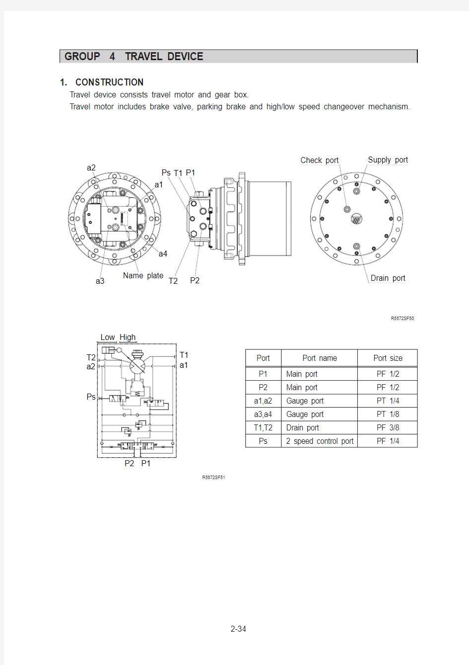
1. CONSTRUCTION
T ravel device consists travel motor and gear box.
T ravel motor includes brake valve, parking brake and high/low speed changeover mechanism.
T2
P2
Drain port
Check port
Ps P1T1Supply port
a3
a2
a4
a1
Name plate
R5572SF50
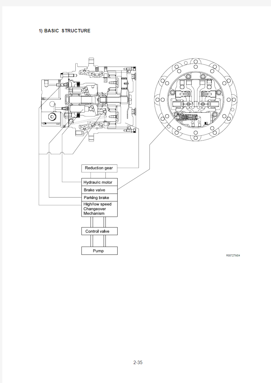
BASIC STRUCTURE 1)
STRUCTURE 2)
2Main shaft
3Swash plate 4Cylinder block 5Piston
6Shoe
7Retainer plate 8Thrust ball
9Timing plate 10Washer
11Collar washer 12Parking piston 13Spring
14Spring
15Friction plate 16Mating plate 18Valve seat 20Spring
21VP plug
22Ring
23Main spool
24Plug
25Spring retainer
26Plug
27Valve
28Spring
30Spring
32Oil seal
33O-ring
35O-ring
36O-ring
37O-ring
38O-ring
40O-ring
41Parallel pin
42Parallel pin
43Socket bolt
44PT plug
45Snap ring
46O-ring
47Back up ring
48Back up ring
49Roller bearing
50Ball bearing
51Roller
52RO plug
54NPTF plug
60Spring
61Piston
63Valve
64Stopper
65Ring
66Spring
67Pivot
68Steel ball
70Socket bolt
74O-ring
75O-ring
76Snap ring
89Name plate
90Rivet screw
91PT plug
101Holder flange
102Floating seal
103Nut ring
105Housing
106Steel ball
107PT plug
108Planetary gear(F)
109Thrust washer
110Screw
111Needle bearing
112Collar
113Thrust plate(F)
114Sun gear
115Snap ring
116Holder
117Planetary gear(R)
118Needle bearing
119Inner race
120Spring pin
122Thrust plate(R)
123Cover
124Socket bolt
125Angular bearing
126O-ring
127O-ring
201Valve block
202Seat
203Plunger
204Spring
205Body
206Shim
207Piston
208Rod
209Plug
210Backup ring
The pressurized oil delivered from the hydraulic pump flows to rear flange(1) of the motor, passes through the brake valve mechanism, and is introduced into cylinder block(4) via timing plate(9). This oil constructively introduced only to one side of (Y1)-(Y2) connecting the upper and lower dead points of stroke of piston(5). The pressurized oil fed to one side in cylinder block(4) pushes each piston(5)(four or five) and generates a force F(kgf)= P(kgf/cm2)YA(cm2).
This force acts on swash plate(3), and is resolves into components(F2 and F3) because swash plate(3) is fixed at an angle ?with the axis of drive shaft(2).
Radial component(F3) generates respective torques (T=F3Yri) for (T1)-(Y2). This residual of torque (T=S(F3Yri)) rotates cylinder block(4) via piston(5). Cylinder block(4) is spline coupled with drive shaft(2).
So the drive shaft(2) rotates and the torque is transmitted.
BRAKE VALVE
Brake released(starting/running)
When the pressurized oil supplied from port (A) the oil opens valve(27) and flows into port (C)at the suction side of hydraulic motor to rotate motor.
At the same time, the pressurized oil passes through pipe line (a) from a small hole in spool(23) and flow into chamber (b).The oil acts on the end face of spool(23)which is put in neutral position by the force
of spring(28), thus causing spool(23) to slide to the left. When spool(23) slides,
port (D)on the passage at the return side
of hydraulic motor, which is closed by the spool groove during stoppage,communicates with port (B)at the tank side
and the return oil from the hydraulic motor runs into the tank. In consequence, the hydraulic motor rotates. Moreover, sliding of spool(23) causes the pressurized oil to flow into ports (P) and (S).
The pressurized oil admitted into port (P) activates piston(12) of the parking brake to release the parking brake force (For details, refer to description of the parking brake).
On the other hand, the pressurized oil introduced into port (S) flows into chamber (t) and presses stopper(57) against the inside of body(55) to prevent spool(58) from moving, thus disabling communication at port (C) side of the hydraulic motor (Suction side and return side of hydraulic motor). When the pressurized oil is supplied from port (B) spool(23) and valve(27) move reversely and the hydraulic motor also rotates reversely .
2)(1)
Brake applied(stopping/stalling)
When the pressurized oil supplied from port (A) is stopped during traveling, no hydraulic pressure is applied and spool(23) which has slided to the left will
return on the right(neutral) via spring retainer(25) by the force of spring(28).The oil in chamber (b) will flow to port (A)side through pipe line (a) in spool(23).However, a back pressure produced by the restricting effect of pipe line (a)
whereby the return speed of spool(23) is controlled.
At the same time, the hydraulic motor will
rotate by the force of inertia even if the pressurized oil is stopped.
Accordingly, the return oil will return to port (B) side from port (D) through a passage between the groove in spool(23)and rear flange(1). When spool(23)completely returns to neutral, the above-mentioned passage is fully closed and the hydraulic motor stops.
As explained above, the hydraulic motor is smoothly braked and stopped by gradually controlling the return oil from the hydraulic motor by the return speed of spool(23), its shape, etc.
However, the hydraulic motor will rotate by the force of inertia. This means that the hydraulic motor will suck oil functioning as a pump.
However, no oil is supplied because the pressurized oil is stopped. In consequence, cavitation occurs on the hydraulic motor, thus adversely affecting it.
At the same time, the passage closed by spool(23), whereby the return oil from the hydraulic motor is enclosed at port (D) side and the pressure is increased.
This pressure slides plunger(203) to the left to short-circuit port (D) and (C) which prevents pressure rise and cavitation (surge cut valve function and anti-cavitation valve function).
Valve(27) is activated by a slight negative pressure to open the oil passage between the oil line at port (A) side and port (C) at the suction side of motor, thus preventing cavitation of the hydraulic motor.
(2)
PARKING BRAKE
Running
When the pressurized oil is supplied from the valve, the spool of brake valve in the hydraulic motor assembly actuates to open the passage to the parking brake and the pressurized oil is introduced into cylinder chamber (a) which is composed of the spindle of reduction gear assembly and piston(12).
When the hydraulic pressure reaches 9kgf/cm 2(0.88Mpa ) or more, it overcomes the force of spring(13) and shifts piston(12) with shift of piston(12) no pressing force is applied to mating plate(16) and friction plate(15) and the movement of friction plate(15) becomes free, whereby the brake force to the cylinder in the hydraulic motor assembly is released.
3)(1)
Stopping
When the pressurized oil from the brake valve is shut off and the pressure in cylinder chamber (a) drops 9kgf/cm 2(0.88Mpa ) or less, piston(12) will return by the force of spring(13).
Piston(12) is pushed by this force of spring(13), and mating plate(16) and friction plate(15) in free condition are pressed against the holder flange of reduction gear assembly .
The friction force produced by this pressing stops rotation of the cylinder and gives a braking torque(8.4kgf ?m (60.8 N ?m )) to the hydraulic motor shaft.
Note that oil control through a proper oil
passage ensures smooth operation.
(2)
valve(63) is pressed toward the left by the force of spring(166), the pressurized oil supply port B is shut off, and oil in chamber (C) is released into the motor case via valve(63).Consequently , swash plate(3) is tilted at a maximum angle(?1á) and the piston displacement of hydraulic motor becomes maximum, thus leading to low-speed rotation.
H IGH/LOW SPEED CHANGEOVER MECHANISM
At low speed-at pilot pressure of less than 10kgf/cm 2(0.98Mpa )
4)(1)
pressure overcomes the force of spring(66) and valve(63) is pressed toward the right. The pressurized oil at supply port (B) is then introduced into chamber (C) via valve(63).Piston(61) pushes up swash plate(3) until it touches side (b) of the holder flange.At this time, swash plate(3) is tilted at a minimum angle(?2á) and the piston displacement of hydraulic motor becomes maximum, thus leading to high-speed rotation.
A t high speed-at pilot pressure of 20kgf/cm 2(1.96Mpa ) or more
(2)
Reduction ratio=(Housing T eeth/Drive Gear T eeth + 1)
Y(Housing T eeth/Sun Gear T eeth + 1) - 1.