外文资料:
Robots
1. Introduction
Nowadays, the applications of machines and robots to assist human in performing their tasks has become increasingly extensive. In industrial applications, the use of robotics system has reached the level which surpasses human ability in terms of speed and accuracy. On the other hand, in the field of domestic robots or service robots, the developments are still far from perfection. The main factor that distinguishes industrial robots from service robots is their working environment. For a service robot to perfectly perform its tasks, it needs to be able to adapt and cope with the normal human living environment. From the practical point of view, bipedal robot is the most suitable robot structure due to its similarity of physical configuration with human especially in terms of locomotion method. However, the realization of bipedal robot is more challenging compared to other types of mobile robot due the unstable nature of bipedal walking. Therefore, many studies have been carried out especially concerning the stability sensing and control strategies of bipedal robot. The common approach in defining the stability of bipedal robot is by using the “Zero Moment Point” (Z MP) criterion [1]. The simplest implementation of ZMP is to generate the joint trajectories based on the pre-planned walking gait while maintaining the ZMP at the given references, but this approach has a limitation in maintaining the balance if there is any unknown external disturbance [2-5]. Many studies specifically focus on the techniques to monitor the real-time ZMP position from the physical system and used it as the feedback component [6-9]. Takanishi and Kato [7] proposed a method to monitor the ZMP position by measuring the force and moment acting on the robot’s shank by using universal forcemoment sensor. Another method utilizes an array of force sensitive resistor placed on the sole of the robot’s foot to obtain the ground reaction force at different locations of the foot. The reaction forces measured from the sensor array is then used to compute the position of the center of pressure which reflects the position of the ZMP [9]. The inverted pendulum technique is another alternative for analyzing the robot stability [10]. This method monitor the instability by constantly reading the body acceleration and tilt angle by means of accelerometer and gyroscope. However, the readings from both sensors are subject to noise and drift during the operation and the effort to apply filters in correcting the measurements often requires considerable amount of computing power [11]. This paper proposed a novel method for sensing and stability control of bipedal robot. The use of specially designed flexible ankle joint allows fast detection and prediction of robot sideway instability. Placing an additional one degree-offreedom rotary joint with built-in angle detection sensor at the robot ankle allows the robot’s body to tilt freely in any sideway direction and detect the tendency of imbalance that may potentially occur. Based on this essential sensor’s information, the controller will quickly adjust position of the counterbalance mass located at the robot waist in order to restore the sideway balance of the robot. The advantage of using counterbalance mass and rotary joint at the ankle is to allow the walking subsystem and sideway balancing subsystem of the robot to be decoupled from each other and work in
independently controlled modes. It is different from the traditional approach when the robot’s posture is corrected to satisfy both conditions at once, smooth forward walking and continuous sideway (sagittal) stability. Details of the proposed method are presented as follows. In section 2 the locomotion mechanism, ankle structure, sensing technique and balancing strategy are introduced. Section 3 discusses the mathematical model of the system. In section 4 experiment method is discussed and the viability of the proposed system is proven by the experimental result. Finally, the conclusions are described in section 5.
2. Mechanical Structure of Biped Robot
2.1. Robot locomotion mechanism
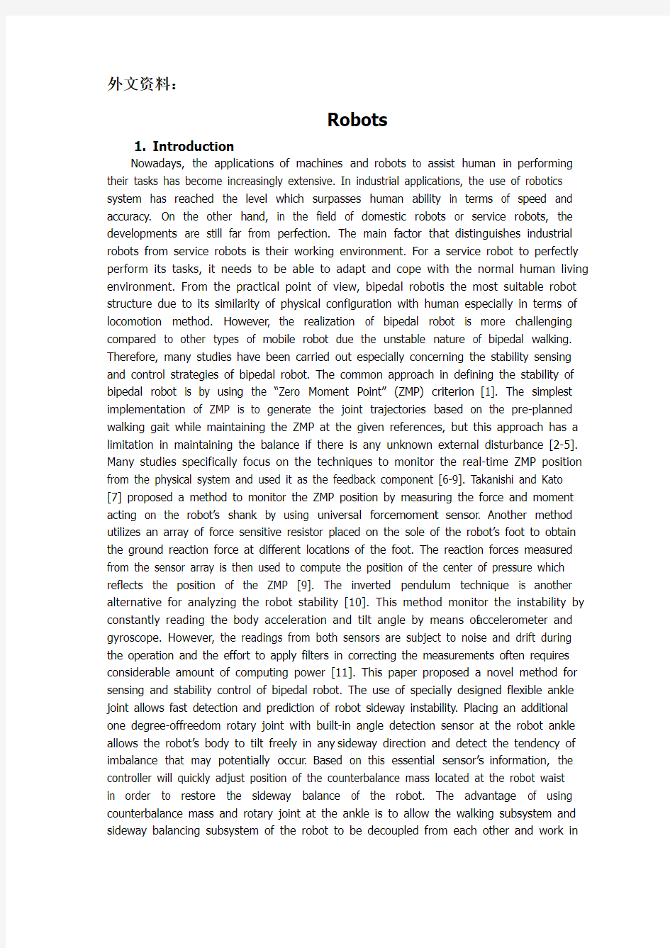
The biped robot is designed to realize two dimensional walking with minimum number of actuations. The locomotion system of the robot consists of four actuators, two for the hip joints and two for the knee joints. The ankle joint is not actuated by any actuators but instead it utilizes a series of parallelogram mechanism to passively control the ankle joint in order to maintain the position of the foot. The usage of parallelogram mechanism provides benefits by reducing the number of actuators needed which results in the simplification of the mechanism design and reduction of the overall robot’s weight. Fig 1(a) shows the stick diagram of the leg in different configuration. The orientation of link a is always parallel to the hip due to the constraint applied by link 1 and link 2. The orientation of link b which represents the foot is always parallel to link a due to the constraint applied by link 3 and link 4. Therefore, the foot is always kept parallel by the parallelogram mechanism regardless of any configuration of the leg. Fig 1(b), (c) show the physical implementation of the parallel leg in different postures. The prototype of the biped robot is mainly constructed using hollow sections of extruded aluminium due to its lightness and strength. The overall height of the biped robot is 0.9 m with the total weight of 7 kg. The length for both thigh and shank are 0.3 m and the spacing between two legs is 0.15 m. For the actuation, each joint is equipped with Robotis Dynamixel RX-64 Smart Actuator, which combines gear transmission, controller, driver and network function in a single package. The output of the hip motor is connected directly to the hip joint and the output of the knee motor is transmitted to the knee joint via a four bar linkage. The purpose of placing the actuators on the hip is to reduce the weight of the leg which will minimize the dynamics forces created by the leg movement. The other advantage of this structural arrangement is that the angular count at each joint is always referenced to the fixed vertical axis of the stationary world coordinate frame regardless of the leg postures.
(a) (b) (c)
Fig. 1. (a) Stick diagram of parallelogram leg; (b), (c) Robot standing with different leg configurations
2.2. Flexible ankle joint to utilize stability measurement
In order to achieve a stable walk on a biped robot, the ability to accurately detect any possible instability is quite crucial. This paper introduces a new approach of sensing the instability by introducing an additional degree of freedom in sideway direction next to the ankle joint. Fig 2(a) shows the structure of that degree of freedom where the free rotary joint on the frontal plane is placed at the ankle between the foot and ankle joint. It will let the unconstrained robot body standing on one leg to tilt (angle ) freely in sideway (sagittal) direction for any possible disturbance in that direction. By installing a rotary sensor on the free joint the controller will be able to detect instantly any instability and immediately react to restore the balance.
(a)(b)
Fig. 2 (a) Schematic picture of the flexible ankle structure; (b) Physical implementation of
flexible ankle
2.3. Split balancing mass for faster system response
The walking cycle of bipedal robot consists of single support phase and double support phase which are executed sequentially and repeatedly. In single support phase, the robot is standing on one leg while another leg is transferred forward. During this phase, the robot body will be tilted sideways due to the unbalanced torque created by the weight of the lifted leg and the dynamic forces generated due to the leg movement. In order to maintain stability of the robot, a set of counterbalance masses are located at a specific position to compensate the unbalanced mass of the lifted leg and other possible disturbance. Fig 3 shows the simplified 3-masses model of bipedal robot: mL represents the lumped mass of the hanging leg, mB1 represents the major balancing mass and mB2 represents the minor balancing mass.
Major balancing mass is mainly used to compensate the weight of the lifted leg. This mass is positioned at a precalculated location in order to balance the torque created by the mass of the lifted leg mL. The minor balancing mass mB2 is continuously repositioned based on the information gathered from the sensor located at the additional ankle joint. This mass works as a counterbalance to maintain the robot to be always vertical regardless of any external sideway disturbance.
The use of two separate counterbalance masses provides several advantages such as:
? Faster response time can be achieved by only moving small inerti a counterbalancing mass instead of moving a larger one,
? Energy efficiency can be improved by reducing load of the motor that drives a smaller inertia counterbalancing mass.
Fig. 3 Simplified model of the bipedal robot
3. System modeling and control
From the diagram on Fig 3, the dynamic equation using Newton’s second law about point O gives:
Σ
(1)Since the major balancing mass is mainly use to compensate for the torque created by the weight of the hanging leg , the major balancing mass can be positioned at the pre-calculated location on the opposite side of the hanging leg. The required position of the major balancing mass can be calculated based on the equilibrium of torque at point O as follows:
Σ
(2)Substituting from Eq.(2) into L.H.S of Eq.(1) gives:
(3)
Rearranging the differential equation from Eq.(3) gives:
(4)
The differential equation in Eq.(4) has two distinct parts. The right hand side only presents parts of the ordinary differential equation with constant time invariant coefficients and the left hand side presents all remaining parts of the equation. Therefore, the left hand side includes:
● Non-linear functions of the main dependent argument, namely ,
●Additional but independent from the main argument parameter
●The parameters that comprises both a and arguments, namely
Fig 4 shows the simplified control block diagram of the balancing system. The PID controller constantly monitors the tilt angle () from the sensor of the additional ankle joint and compares the reading with that of the desired angle. If any tilt is detected, the controller will actuate the balancing mass to the opposite direction in order to regain the balance.
Fig. 4 Simplified block diagram of the stability control system
4. Experimental results
The experiment is carried out to verify the effectiveness of the proposed mechanical structure and control strategies in maintaining the robot’s balance in single support p hase. During the experiment, the robot is standing on one leg with another leg lifted up and floating. The external disturbance is applied by making a push on the edge of the robot’s hip which will cause the robot to tilt sideways (Fig 5(a)). The intensity of the pushing force is measured by a force sensor mounted on the hip (Fig 5(b)).
Fig 6 shows the measurement of the tilt angle from the additional ankle joint, balancing mass position a and the disturbance force when the external disturbance is applied. It is apparent from the figure that once the disturbance is applied the sensor detects change in tilt angle and the controller immediately reacts by moving the mass to the opposite direction of the tilt in order to regain the balance. Fig 7 shows the measurement when an excessive disturbance force is applied approximately at the 37th seconds, the tilt angle changes abruptly and the balancing mass is not able to recover the balance. The saturated angle measurement at the end of the plots indicates that the robot is falling. It is due to the fact that the value of minor mass mB2 and the allowable range of
its motion a are limited in this design. The overall resistance to the externally generated force can be increased by either increasing mB2 or a.
(a) (b)
Fig. 5 (a) Hip plane of the robot; (b) Force sensor attachment to measure applied
disturbance force
Fig. 6. System response to disturbance (balance maintained)
Fig. 7. System response to disturbance (excessive force applied)
5. Conclusion
This paper presents stability control method for bipedal walking robot which includes the leg design with additional (redundant) degree of freedom at the ankle joint and split balancing mass. The proposed method enables the sensing, control and balancing of bipedal robot to be implemented in a simple yet cost effective manner. The effectiveness of the design method is proven by the experimental results. The implementation of this method also allows the walk controlling algorithms to be decoupled from the stability control algorithms to increase the system response time.
References
[1] Vukobratovic M., Juricic D., 1969. Contribution to the synthesis of biped gait, IEEE Transaction on Biomedical Engineering 16, p.1-6.
[2] Erbatur K., Kurt O., 2006. “Humanoid Walking Robot Control with Natural ZMP References,” IEEE Industrial Electronics - Proceedings of the 32nd Annual Conference, p. 4100-4106.
[3] Lim H.-ok, Setiawan S. A., Takanishi A., 2001. “Balance and impedance control for biped humanoid robot locomotion,” Intelligent Robots and Systems - Proceedings of the 2001 IEEE/RSJ International Conference, p. 494-499.
[4] Liu L., Zhao M., Lin D., Wang J., Chen K., 2003. “Gait designing of biped robot according to human walking based on six-axis force sensors,”Computational Intelligence in Robotics and Automation - Proceedings of the 2003 IEEE International Symposium, p.
360–365.
[5] Sardain P., Bessonnet G., 2004. Zero moment point-measurements from a human walker wearing robot feet as shoes, IEEE Transactions on Systems, Man and Cybernetics, Part A: Systems and Humans 34, p. 638–648.
[6] Loffler K., Gienger M., Pfeiffer F., Ulbrich H., 2004. Sensors and control concept of a biped robot, IEEE Transactions on Industrial Electronics 51, p. 972-980.
[7] Takanishi A., Kato I., 1991. “A biped walking robot having a ZMP measurement system using universal force-moment sensors,” Intelligent Robots and Systems - Proceedings of the 1991 IEEE/RSJ International Workshop, p. 1568-1573.
[8] Kagami S., Takahashi Y., Nishiwaki K., Mochimaru M., Mizoguchi H., “High-speed matrix pressure sensor for humanoid robot by using thin force sensing resistance rubber sheet,” Sensors - Proceedings of the 2004 IEEE Conference, p. 1534–1537.
[9] Kalamdani A., Messom C., Siegel M., 2007. Robots with sensitive feet, IEEE Instrumentation and Measurement Magazine 10, p. 46–53.
[10] Caux S., Mateo E., Zapata R.,1998. “Balance of biped robots: special double inverted pendulum” Systems, Man and Cybernetics - IEEE International Conference, p. 3961-3969.
[11] Braunl T., 2006. Embedded Robotics, Springer, Germany.
译文资料:
机器人
1、介绍
现在,机械和机器人的应用帮助人类执行他们的任务已经变得越来越广泛。在工业应用中,使用机器人系统已经达到了在速度和准确度上超过人类能力的水平。另一方面,在家用或服务机器人的领域,发展的还很不完善。区别工业机器人和服务机器人的主要因素在于它们的工作环境。对于服务机器人,去完美的执行它的任务,需要适应和应对正常人的生活环境。来自实践的观点,双足机器人是最合适的机器人结构,这归因于它的身体形态与人类相似,特别在运动方法方面(in terms of)。然而,由于双足行走不稳定的天性,对比其它类型的移动机器人,双足机器人的实现(realization)更具挑战。因此,很多研究一直在继续,尤其关心双足机器人的稳定感和控制策略。
通常定义双足机器人稳定性的途径是使用“零力矩点”(ZMP)标准。ZMP最简单的实施办法是设法产生一个基于预先计划行走步法的节点轨迹,同时保持ZMP有一个给定参考,但是这个途径在存在不明外部干扰的情况下有一个限制。许多技术研究尤其关注从物理系统中监视ZMP的实时位置,并且把它当作反馈元件。T akanishi和Kato提出了一个监视ZMP 位置的方法,就是通过使用普通的力学传感器测量作用于机器人小腿的力和力矩。另一种方法是利用大量的布置在机器人脚底的力敏传感器,去获得脚底上不同位置的地面反作用力。随后用这些传感器阵列测得的数据计算出能反映ZMP中心位置的受力中心。
倒立摆技术是另一个可供选择的分析机器人稳定性的方法。这个方法通过加速度计和陀螺仪不断读取身体加速度和倾角信息,来监测不稳定性。然而,从这两个传感器读到的数据受制于(be subject to)操作过程中的噪声和漂移,并且修正测量数据的努力需要强大的计算能力。
本文提供了双足机器人的感知和稳定控制的新方法。使用特制的灵活踝关节,快速探测和预报机器人的侧面失稳。在机器人的踝关节上放置一个额外的单自由度角位移传感器,允许机器人向任何方向自由倾斜,探测潜在发生的不稳趋势。基于这个必要的传感器的信息,控制器将会快速调整平衡块的位置,为了恢复机器人的侧面平衡,抵消聚集在机器人腰部的不平衡力。使用平衡块和回转头的优势在于让行走子系统和平衡子系统彼此不挂钩,并运行在独立的两个控制模块里。这与传统方法不同,当机器人的姿态同时满足两个条件,顺利的向前行走和不断地稳定调整。
该方法提出了如下(as follows)的细节。第二节介绍了运动装置、关节结构、测知技术和平衡策略。第三节讨论了系统的数学模型。第四节,用实验结果证实了所讨论的实验方法和所提出系统的可行性。最终,第五章描述了结论。
2、双足机器人的机械结构
2.1 机器人行走机构
设计双足机器人的目的是驱动最小量实现二维面的行走。机器人的运动系统包含了四个驱动器,两个用在髋关节,两个用于膝关节。踝关节不由驱动器驱动,但是代替它的是一系列的平行四边形机构,来被动控制踝关节,为维持脚的位置。使用平行四边形机构能提供利益通过减少所需驱动器的数量,还能简化机械设计,减轻机器人质量。
图1(a)展示了机械腿在不同位置下的符号图。由于1杆和2杆的约束作用,A杆的连接方向总是跟臀部平行。由于3杆和4杆的约束作用,B杆(脚)的连接方向始终跟A 杆平行。这样,脚总是通过平行四边形机构保持平行,不管腿怎样配置。图1(b)(c)展
示了平行的腿在不同姿态下的物理实现。
出于轻盈和强度的需要,双足机器人的模型主要使用挤制铝材的空心管构造。机器人全高0.9m,总质量7kg。每条大腿和小腿的长度为0.3m,两腿间距0.15m。
为了驱动,每个关节配备有Robotis Dynamixel RX-64 Smart Actuator,它结合了齿轮传动装置、控制器、驱动程序和网络功能在单一封装里。臀部的输出马达直接连接臀部关节,膝盖的输出马达通过四杆机构给膝盖传递动力。把驱动器放在臀部的目的是减轻腿部的重量,这样可以让使腿部运动的驱动力最小化。这种结构布局的其它优势在于不管腿的姿势,每个关节的角度计算都能参照固定坐标系的纵轴。
(a)(b)(c)
图1(a)平行四边形腿的符号图;(b),(c)机器人腿在不同配置下的站立图
2.2 灵活的踝关节利用稳定的测量
为了在双足机器人上实现稳定行走,精确探测任何可能不稳的能力十分重要。本文介绍了一种新的测知不稳的途径,通过在侧面引进一个额外的自由度放在踝关节之后。图(2)展示了前面板上自由旋转节的结构,它被放在脚和踝关节的连接之间。这将会让无约束的机器人在身体站立的同时,一只脚能在侧面(矢状面)方向自由倾斜(角度θ)任意可能的距离。通过在自由关节处安装角位移传感器,控制器将能够立刻(instantly)探测到任何不稳并立即(immediately)反应恢复平衡。
(a)(b)
图2(a) 灵活踝关节的结构图片;(b)灵活踝关节的物理实现
2.3 分割平衡块为更快的系统响应
双足机器人的行走周期包含被顺序(sequentially)和循环(repeatedly)执行的单足支
撑阶段和双足支撑阶段。在单足支撑阶段,当机器人另一条腿移动时,一条腿站立。在这个阶段,由于抬腿重量产生(created)的不平衡扭矩以及腿部运动产生(generated)的动态力,机器人的身体会向侧面倾斜。
为了保持机器人的稳定,一套抵消平衡质量块被放置在特别的位置去补偿抬腿的不平衡质量。图(3)展示了已简化的双足机器人3质量块模型:代表腿在挂立时的集中质量,代表主要质量平衡块,代表次要质量平衡块。
主要质量平衡块主要用于抬腿时的重量补偿。为了平衡抬腿质量产生的扭矩,这个质量块被安放在预先计算好的位置。次要质量平衡块基于放置在踝关节的额外传感器收集到的信息,不断改变位置。这个质量块作为一个平衡力维持机器人垂直,无论侧面怎么受干扰。
使用两个分离的平衡质量块能提供不少优势,例如:
●获得更快的响应时间,能使平衡质量块移动很小的距离,而不是很大距离,
●能源效率能提高,通过驱动小的平衡质量块,减少电机的负载。
图3 双足机器人的简化模型
3.系统模型和控制
图3中,动力方程使用牛顿第二定律关于坐标系原点O给出:
Σ
(1)
由于主要的平衡质量块主要用于补偿悬挂着的腿的重量所产生的扭矩,主要平衡质量块能放置在预先计算好的位置,在悬挂腿的相反方向。主要平衡质量块所需的位置
能基于在坐标系原点计算出的平衡扭矩,建立方程如下:
Σ
(2)把方程(2)中的代入方程(1)得:
(3)整理方程(3)得:
(4)
方程(4)中的微分方程有两个明显的部分。等式的右边只列出了常微分方程系数不随时间变化的部分,左边列出了方程全部的剩余部分。因此,等式左边包含:
●主要取决于角度θ的非线性方程,即,
●额外的独立于主要角度θ的参数
●包含角度和的参数,即
图(4)展示了已简化的平衡系统的控制框图。这个PID控制器从附加的踝关节传感器中不断监视倾斜角(θ),比较读取值与所需值。若有一点倾斜被检测到,控制器就会驱动平衡块去反向运动,恢复平衡。
图4 已简化的稳定控制系统的方框图
4.实验结果
这个实验证实了所提机械结构和控制策略在维持单腿支撑机器人身体平衡的有效性。在实验期间,机器人一条腿站立,另一条腿抬起或浮空运动。
图6显示了来自额外踝关节连接的倾角的测量,平衡质量块的位置和实施外部干扰时产生的扰动。一旦在身体上实施明显干扰,传感器就会探测到倾角变化然后控制器立即通过移动质量块向反方向倾斜来使机器人恢复平衡。图7展示了当外部干扰施加过多时大约37秒,倾角突然改变,平衡质量块不能再恢复平衡。最后环节的饱和角度测试表明机器人正在摔倒。由于次要平衡质量块的价值和运动a的允许范围在设计中被限制。全部对外力的抵抗能通过增加参数和a的大小得到提高。
(a) (b)
图5(a)机器人的臀部平台;(b)测量干扰外力的力传感器连接
图(6)系统对干扰的响应(维持平衡)
图(7)系统对干扰测响应(施力过度)
5.结论
本文介绍了双足步行机器人稳定控制方法,包括腿部额外在踝关节的自由度和分裂平衡质量设计。该方法使感知、控制和平衡双足机器人以简单而有效的方式实现的。设计方法的有效性通过实验结果证明。这个方法还允许行走控制的实现算法与稳定控制算法无关,提高系统的响应速率。
参考
[1]Vukobratovic米。,Juricic D。,1969年。贡献的合成两足动物步态,IEEE事务在生物医学工程16日p.1-6。
[2]Erbatur K。,库尔特·O。,2006年。“仿人步行机器人控制与自然ZMP引用,“IEEE工业电子,第32届研讨会论文集,页4100 - 4106。
[3]Lim H。-好的,塞。Takanishi。,2001年。“平衡和阻抗控制的两足动物仿人机器人运动,“智能机器人和系统——2001 IEEE / RSJ国际研讨会论文集,p . 494 - 499。
[4]刘L。,赵米。林,D。王,J。陈,K。,2003年。“两足机器人的步态设计基于基础力传感器,根据人类行走”计算智能机器人与自动化学报2003年IEEE国际研讨会,p . 360 - 365。
[5]Sardain P。Bessonnet G。,2004年。零时刻point-measurements沃克从人类机器人的脚穿鞋,IEEE系统,人与控制论,一个部分:系统和人类34,p . 638 - 648。
[6]Loffler K。基恩戈尔,M。菲佛F。,Ulbrich H。,2004年。传感器和控制两足机器人的概念,IEEE工业电子51,p . 972 - 980。
[7]Takanishi。我,加藤。,1991年。“两足步行机器人ZMP使用通用force-moment传感器测量系统,“智能机器人和系统-学报1991年IEEE / RSJ国际研讨会,页1568 - 1573。[8]Kagami年代。,高桥Y。,Nishiwaki K。,Mochimaru米。沟口健二小时。,“高速矩阵压
力传感器为仿人机器人通过使用薄力传感电阻橡胶板,“传感器——2004年IEEE会议程序,p . 1534 - 1537。
[9]Kalamdani。,Messom C。,西格尔米。,2007年。机器人敏感的脚,IEEE仪表和测量杂志10日46-53页。
[10]Caux年代。马特奥E。萨帕塔R。1998。“两足机器人的平衡:特殊双倒立摆”系统,人与控制论IEEE国际会议,p . 3961 - 3969。
[11]Braunl T。,2006年。嵌入式机器人,德国施普林格。
四足步行机器人研究现状及展望 (郑州轻工业学院机电工程学院河南郑州) 摘要:文章对国内外四足步行机器人研究现状进行了综述,归纳分析了四足机器人质心距离测量系统研究的关键技术,并展望了四足机器人的发展趋势。 关键词:四足步行机器人;研究现状;关键技术;发展趋势 引言:目前,常见的步行机器人以两足式、四足式、六足式应用较多。其中,四足步行机器人机构简单且灵活,承载能力强、稳定性好,在抢险救灾、探险、娱乐及军事等许多方面有很好的应用前景,其研制工作一直受到国内外的重视。1国内外研究四足步行机器人的历史和现状 20世纪60年代,四足步行机器人的研究工作开始起步。随着计算机技术和机器人控制技术的研究和应用,到了 20 世纪 80 年代,现代四足步行机器人的研制工作进入了广泛开展的阶段。 世界上第一台真正意义的四足步行机器人是由 Frank 和 McGhee 于 1977 年制作的。该机器人具有较好的步态运动稳定性,但其缺点是,该机器人的关节是由逻辑电路组成的状态机控制的,因此机器人的行为受到限制,只能呈现固定的运动形式[1]。 20 世纪 80、90 年代最具代表性的四足步行机器人是日本 Shigeo Hirose 实验室研制的 TITAN 系列。1981~1984年Hirose教授研制成功脚部装有传感和信号处理系统的TITAN-III[2]。它的脚底部由形状记忆合金组成,可自动检测与地面接触的状态。姿态传感器和姿态控制系统根据传感信息做出的控制决策,实现在不平整地面的自适应静态步行。 TITAN-Ⅵ[3]机器人采用新型的直动型腿机构,避免了上楼梯过程中各腿间的干涉,并采用两级变速驱动机构,对腿的支撑相和摆动相分别进行驱动。
英文原文出自《Advanced Technology Libraries》2008年第5期 Robot Robot is a type of mechantronics equipment which synthesizes the last research achievement of engine and precision engine, micro-electronics and computer, automation control and drive, sensor and message dispose and artificial intelligence and so on. With the development of economic and the demand for automation control, robot technology is developed quickly and all types of the robots products are come into being. The practicality use of robot products not only solves the problems which are difficult to operate for human being, but also advances the industrial automation program. At present, the research and development of robot involves several kinds of technology and the robot system configuration is so complex that the cost at large is high which to a certain extent limit the robot abroad use. To development economic practicality and high reliability robot system will be value to robot social application and economy development. With the rapid progress with the control economy and expanding of the modern cities, the let of sewage is increasing quickly: With the development of modern technology and the enhancement of consciousness about environment reserve, more and more people realized the importance and urgent of sewage disposal. Active bacteria method is an effective technique for sewage disposal,The lacunaris plastic is an effective basement for active bacteria adhesion for sewage disposal. The abundance requirement for lacunaris plastic makes it is a consequent for the plastic producing with automation and high productivity. Therefore, it is very necessary to design a manipulator that can automatically fulfill the plastic holding. With the analysis of the problems in the design of the plastic holding manipulator and synthesizing the robot research and development condition in recent years, a economic scheme is concluded on the basis of the analysis of mechanical configuration, transform system, drive device and control system and guided by the idea of the characteristic and complex of mechanical configuration,
附录外文文献 原文 Industrial Robots Definition “A robot is a reprogrammable,multifunctional machine designed to manipulate materials,parts,tools,or specialized devices,through variable programmed motions for the performance of a variety of tasks.” --Robotics Industries Association “A robot is an automatic device that performs functions normally ascribrd to humans or a machine in orm of a human.” --Websters Dictionary The industrial robot is used in the manufacturing environment to increase productivity . It can be used to do routine and tedious assembly line jobs , or it can perform jobs that might be hazardous to do routine and tedious assembly line jobs , or it can perform jobs that might be hazardous to the human worker . For example , one of the first industrial robots was used to replace the nuclear fuel rods in nuclear power plants . A human doing this job might be exposed to harmful amounts of radiation . The industrial robot can also operate on the assembly line , putting together small components , such as placing electronic components on a printed circuit board . Thus , the human worker can be relieved of the routine operation of this tedious task . Robots can also be programmed to defuse bombs , to serve the handicapped , and to perform functions in numerous applications in our society . The robot can be thought of as a machine that will move an end-of-arm tool , sensor , and gripper to a preprogrammed location . When the robot arrives at this location , it will perform some sort of task . This task could be welding , sealing , machine loading , machine unloading , or a host of assembly jobs . Generally , this work can be accomplished without the involvement of a human being , except for programming and for turning the system on and off . The basic terminology of robotic systems is introduced in the following :
基于单片机控制的双足行走机器人设计 摘要:21世纪机器人发展日新月异,从传统的履带式机器人到如今的双足行走机器人,机器人的应用范围越来越广。本系统以单片机(STC89c52)为系统的中央控制器,以单片机(STC12c5410ad)为舵机控制模块。将中央控制器与舵机控制器,舵机,各类传感设备及受控部件等有机结合,构成整个双足行走机器人,达到行走、做动作的目的。单片机中央控制器与舵机控制器以串口通信方式实现。系统的硬件设计中,对主要硬件舵机控制器和STC89C52单片机及其外围电路进行了详细的讲述。硬件包括舵机控制器,STC12C5410AD 单片机,按键,各种传感器和数据采集与处理单元。软件包括单片机初始化、主程序、信号采集中断程序、通过串口通讯的接收和发送程序。论文的最后部分以双足行走机器人为基础,结合传感器,外围控制设备组成控制系统,并给出了此系统应用领域的一些探讨和研究。 关键词:单片机;舵机控制; STC12C5410AD
Bipedal robot design based on MCU Abstract:In the 21st century robot development changes with each passing day, from the traditional crawler robot to now bipedal robot, the robot's application scope is more and more widely.This system by single chip microcomputer (STC89c52) as the central controller in the system, STC12c5410ad MCU as the steering gear control module. The central controller and the servo controller, Steering gear, all kinds of sensing and control components such as organic combination, make up the whole bipedal robot, the purpose of to walk, do the action.Single chip microcomputer central controller and the servo controller to realize serial communication way.System hardware design, the main hardware servo controller and STC89C52 single-chip microcomputer and peripheral circuit in detail. Hardware including servo controller, STC12C5410AD micro controller, buttons, all kinds of sensor and data acquisition and processing unit. Software includes MCU initialization, the main program, and interrupts program signal collection, through a serial port communication to send and receive procedures. The last part of the paper on the basis of bipedal robot, combined with the sensor, the peripheral control device of control system, this system is also given some discussions and research in the field of application. Keywords:MCU; Servo Control; STC12C5410AD
中英文资料对照外文翻译 FEM Optimization for Robot Structure Abstract In optimal design for robot structures, design models need to he modified and computed repeatedly. Because modifying usually can not automatically be run, it consumes a lot of time. This paper gives a method that uses APDL language of ANSYS 5.5 software to generate an optimal control program, which mike optimal procedure run automatically and optimal efficiency be improved. 1)Introduction Industrial robot is a kind of machine, which is controlled by computers. Because efficiency and maneuverability are higher than traditional machines, industrial robot is used extensively in industry. For the sake of efficiency and maneuverability, reducing mass and increasing stiffness is more important than traditional machines, in structure design of industrial robot. A lot of methods are used in optimization design of structure. Finite element method is a much effective method. In general, modeling and modifying are manual, which is feasible when model is simple. When model is complicated, optimization time is longer. In the longer optimization time, calculation time is usually very little, a majority of time is used for modeling and modifying. It is key of improving efficiency of structure optimization how to reduce modeling and modifying time. APDL language is an interactive development tool, which is based on ANSYS and is offered to program users. APDL language has typical function of some large computer languages. For example, parameter definition similar to constant and variable definition, branch and loop control, and macro call similar to function and subroutine call, etc. Besides these, it possesses powerful capability of mathematical calculation. The capability of mathematical calculation includes arithmetic calculation, comparison, rounding, and trigonometric function, exponential function and hyperbola function of standard FORTRAN language, etc. By means of APDL language, the data can be read and then calculated, which is in database of ANSYS program, and running process of ANSYS program can be controlled.
目录 第1章序言 (2) 1.1 双足机器人现状 (2) 1.2 技能综合训练意义 (2) 1.3 技能训练的内容 (2) 第2章元件选择、结构设计 (3) 2.1元件选择 (3) 2.2结构设计三维设计图 (4) 2.2.1零件三位模型以及装配 (4) 2.2.2装配三维模型 (7) 第3章控制系统设计 (10) 第4章系统软件编程与仿真 (12) 第5章结论...................................................................... 错误!未定义书签。参考文献 (17)
第1章序言 1.1双足机器人现状 随着世界第一台工业机器人1962年在美国诞生,机器人已经有了三十多年的发展史。三十多年来,机器人由工业机器人到智能机器人,成为21世纪具有代表性的高新技术之一,其研究涉及的学科涵盖机械、电子、生物、传感器、驱动与控制等多个领域。 世界著名机器人学专家,日本早稻田大学的加藤一郎教授说过:“机器人应当具有的最大特征之一是步行功能。”双足机器人属于类人机器人,典型特点是机器人的下肢以刚性构件通过转动副联接,模仿人类的腿及髋关节、膝关节和踝关节,并以执行装置代替肌肉,实现对身体的支撑及连续地协调运动,各关节之间可以有一定角度的相对转动。 双足机器人不仅具有广阔的工作空间,而且对步行环境要求很低,能适应各种地面且具有较高的逾越障碍的能力,其步行性能是其它步行结构无法比拟的。研究双足行走机器人具有重要的意义 1.2技能综合训练意义 技能训练是在学生修完除毕业设计外全部理论和时间课程以后的一次综合性时间教学环节,其目的和意义在于: 通过技能训练,了解机器人机构及控制系统设计的基础知识; 掌握机器人系统中元部件的正确选择方法和特性参数的确定; 培养学生对所学知识的综合应用,理论联系实际的能力; 培养学生的动手能力和实际操作能力; 1.3技能训练的内容 1、主要内容: 1)、机器人结构设计; 2)、控制系统软硬件设计与仿真; 3)、八自由度机器人运动控制。 2、训练形式 学生以小组为单位,集体讨论确定整体方案;指导教师给出实训方向,技术指标等,协助学生完成训练任务。
自制六自由度双足机器人 一、制作六自由度双足机器人步骤: 1、确定舵机:舵机的好坏直接影响机器人的效果; 2、自制舵机后盖:它是连接舵机和U型架的重要组成部件;(买一 个标准的舵机后盖是最好不过,但你的动手能力 和思考问题解决问题的能力就没有提高,因此我 选择自制一个舵机后盖) ①选择铁皮为制作材料; ②测量舵机尺寸,截取合适铁皮条(尺寸为20mm*116mm); ③折弯,注意左右对称; ④确定固定用定位孔的位置,并使用1mm钻头打孔; ⑤打固定用螺丝孔(使用3mm钻头); ⑥确定舵机输出同轴定位孔的位置,并使用1mm钻头打孔; ⑦打舵机输出同轴螺丝孔(使用3mm钻头); ⑧打舵机后盖过线孔(6mm*8mm); 注:脚上的舵机后盖比较特殊,要考虑它要和脚底板相连,我的解决方法是在上述舵机后盖的基础上,增加宽度,并折弯,打孔,同脚底板相连。 3、自制U型架:在双足机器人中,舵机相当于人的关节,那U型架 就是人的骨骼。U型架的制作:(以下是我的设计, 可根据具体需求,自行设计尺寸) ①选择铝合金板(厚度一般为1.5mm);
②将铝合金板切成细条(尺寸为20mm*116mm); ③折弯,注意左右高度相等; ④打定位孔(使用1mm钻头),注意孔的位置以U型架的“U” 字底为基准; ⑤打螺丝孔(使用3mm钻头); ⑥磨削加工。 4、自制脚底板:脚底板的设计可以多种多样,但要保证一点,即机 器人抬脚走路时,要保证重心用你设计的脚底板可 以承受得住。 5、自制机器人腰部:其实就是连接两条腿的部件,长宽是根据设计 的脚底板的大小确定的。 二、需要注意的问题: 1、机器人左右质量要保证尽量一致,否则走路会有偏差。 2、制作部件时,要注意基准。 三、软件编程: 软件编程,主要是靠控制舵机旋转不同的角度。
成绩 采用ADAMS和MATLAB建立机械装置或机电装置虚拟样机 ——四足机器人建模与仿真 实验报告 院(系)名称自动化科学与电气工程 专业名称控制工程 学生学号0 学生姓名0 指导教师0 2016年4月
一、实验背景 1. 参照自然界四足哺乳动物如猫狗的运动形式,对四足机器人进行建模,结合虚拟样机技术软件ADAMS,对四足机器人进行步态规划、运动学和动力学分析,使四足机器人模型良好运行。 2. 利用拉格朗日能量法建立四足机器人坐标系并对四足机器人进行运动学分析。 3.在Solidworks中建立四足机器人三维模型,之后将三维模型导入至虚拟样机软件ADAMS中,在ADAMS中建立虚拟样机模型,并利用样条曲线来规划机器人的运动轨迹,进行仿真,实现机器人的直线行走。 二、实验原理 2.1 研究对象背景分析 移动机器人按移动方式大体分为两大类;一是由现代车辆技术延伸发展成轮式移动机器人(包括履带式);二是基于仿生技术的运动仿生机器人。运动仿生机器人按移动方式分为足式移动、蠕动、蛇行、游动及扑翼飞行等形式,其中足式机器人是研究最多的一类运动仿生机器人。 自然环境中有约50%的地形,轮式或履带式车辆到达不了,而这些地方如森林,草地湿地,山林地等地域中拥有巨大的资源,要探测和利用且要尽可能少的破坏环境,足式机器人以其固有的移动优势成为野外探测工作的首选,另外,如海底和极地的科学考察和探索,足式机器人也具有明显的优势,因而足式机器人的研究得到世界各国的广泛重视。现研制成功的足式机器人有1足,2足,4足,6足,8足等系列,大于8足的研究很少。 曾长期作为人类主要交通工具的马,牛,驴,骆驼等四足动物因其优越的野外行走能力和负载能力自然是人们研究足式机器人的重点仿生对象。因而四足机器人在足式机器人中占有很大的比例,四足机器人的研究深具社会意义和实用价值。 2.2 研究对象数学模型分析 四足机器人整体结构由躯体、左前腿、右前腿、左后腿、右后腿五部分组成。
外文翻译 专业机械电子工程 学生姓名张华 班级 B机电092 学号 05 指导教师袁健
外文资料名称:Research,design and experiment of end effector for wafer transfer robot 外文资料出处:Industrail Robot:An International Journal 附件: 1.外文资料翻译译文 2.外文原文
晶片传送机器人末端效应器研究、设计和实验 刘延杰、徐梦、曹玉梅 张华译 摘要:目的——晶片传送机器人扮演一个重要角色IC制造行业并且末端执行器是一个重要的组成部分的机器人。本文的目的是使晶片传送机器人通过研究其末端执行器提高传输效率,同时减少晶片变形。 设计/方法/方法——有限元方法分析了晶片变形。对于在真空晶片传送机器人工作,首先,作者运用来自壁虎的超细纤维阵列的设计灵感研究机器人的末端执行器,和现在之间方程机器人的交通加速度和参数的超细纤维数组。基于这些研究,一种微阵列凹凸设计和应用到一个结构优化的末端执行器。对于晶片传送机器人工作在大气环境中,作者分析了不同因素的影响晶片变形。在吸收面积的压力分布的计算公式,提出了最大传输加速度。最后, 根据这些研究得到了一个新的种末端执行器设计大气机器人。 结果——实验结果表明, 通过本文研究应用晶片传送机器人的转换效率已经得到显着提高。并且晶片变形吸收力得到控制。 实际意义——通过实验可以看出,通过本文的研究,可以用来提高机器人传输能力, 在生产环境中减少晶片变形。还为进一步改进和研究末端执行器打下坚实的基础,。 创意/价值——这是第一次应用研究由壁虎启发了的超细纤维阵列真空晶片传送机器人。本文还通过有限元方法仔细分析不同因素在晶片变形的影响。关键词:晶片传送机器人末端执行器、超细纤维数组、晶片 1.介绍
中英文对照资料外文翻译文献 FEM Optimization for Robot Structure Abstract In optimal design for robot structures, design models need to he modified and computed repeatedly. Because modifying usually can not automatically be run, it consumes a lot of time. This paper gives a method that uses APDL language of ANSYS 5.5 software to generate an optimal control program, which mike optimal procedure run automatically and optimal efficiency be improved. 1)Introduction Industrial robot is a kind of machine, which is controlled by computers. Because efficiency and maneuverability are higher than traditional machines, industrial robot is used extensively in industry. For the sake of efficiency and maneuverability, reducing mass and increasing stiffness is more important than traditional machines, in structure design of industrial robot. A lot of methods are used in optimization design of structure. Finite element method is a much effective method. In general, modeling and modifying are manual, which is feasible when model is simple. When model is complicated, optimization time is longer. In the longer optimization time, calculation time is usually very little, a majority of time is used for modeling and modifying. It is key of improving efficiency of structure optimization how to reduce modeling and modifying time. APDL language is an interactive development tool, which is based on ANSYS and is offered to program users. APDL language has typical function of some large computer languages. For example, parameter definition similar to constant and variable definition, branch and loop control, and macro call similar to function and subroutine call, etc. Besides these, it possesses powerful capability of mathematical calculation. The capability of mathematical calculation includes arithmetic calculation, comparison, rounding, and trigonometric function, exponential function and hyperbola function of standard FORTRAN language, etc. By means of APDL language, the data can be read and then calculated, which is in database of ANSYS program, and running process of ANSYS program can be controlled.
摘要:对四足机器人研究应用的历史与现状做了介绍,列举出国内外主要研究机构及其主要研究成果,对四足机器人研究的热点和难点问题进行了归纳总结,并展望了四足机器人的发展趋势。 关键词:四足机器人;研究与应用;历史与现状;难点与热点;发展趋势 1. 引言 移动机器人按移动方式大体分为两大类;一是由现代车辆技术延伸发展成轮式移动机器人(包括履带式);二是基于仿生技术的运动仿生机器人。运动仿生机器人按移动方式分为足式移动、蠕动、蛇行、游动及扑翼飞行等形式,其中足式机器人是研究最多的一类运动仿生机器人。 自然环境中有约50%的地形,轮式或履带式车辆到达不了,而这些地方如森林,草地湿地,山林地等地域中拥有巨大的资源,要探测和利用且要尽可能少的破坏环境,足式机器人以其固有的移动优势成为野外探测工作的首选,另外,如海底和极地的科学考察和探索,足式机器人也具有明显的优势,因而足式机器人的研究得到世界各国的广泛重视。现研制成功的足式机器人有1足,2足,4足,6足,8足等系列,大于8足的研究很少。 曾长期作为人类主要交通工具的马,牛,驴,骆驼等四足动物因其优越的野外行走能力和负载能力自然是人们研究足式机器人的重点仿生对象。因而四足机器人在足式机器人中占有很大的比例。长期从事足式机器人研究的日本东京工业大学的広濑茂男等学者认为:从稳定性和控制难易程度及制造成本等方面综合考虑,四足机是最佳的足式机器人形式[1],四足机器人的研究深具社会意义和实用价值。 2. 国内外四足机器人研究历史与现状 四足机器人的研究可分为早期探索和现代自主机器人研究两个阶段。 2.1 四足机器的早期探索 中国古代的“木牛流马”以及国外十九世纪由Rygg设计的“机械马”,是人类对足式行走行机器的早期探索。而Muybridge在1899年用连续摄影的方法研究动物的行走步态,则是人们研究足式机器人的开端。20世纪60年代,机器人进入了以机械和液压控制实现运动的发展阶段。美国学者Shigley(1960)和Baldwin(1966)都使用凸轮连杆机构设计了机动的步行车[2]。这一阶段的研究成果最具代表性的是美国的Mosher于1968年设计的四足车“Walking Truck” [3](图1)。 图1 Walking truck 80年代,随着计算机技术和机器人控制技术的广泛研究和应用,真正进入了具有自主行为的现代足式机器人的广泛研究阶段。
机器人技术发展中英文对照外文翻译文献(文档含英文原文和中文翻译)
外文资料: Robots First, I explain the background robots, robot technology development. It should be said it is a common scientific and technological development of a comprehensive results, for the socio-economic development of a significant impact on a science and technology. It attributed the development of all countries in the Second World War to strengthen the economic input on strengthening the country's economic development. But they also demand the development of the productive forces the inevitable result of human development itself is the inevitable result then with the development of humanity, people constantly discuss the natural process, in understanding and reconstructing the natural process, people need to be able to liberate a slave. So this is the slave people to be able to replace the complex and engaged in heavy manual labor, People do not realize right up to the world's understanding and transformation of this technology as well as people in the development process of an objective need. Robots are three stages of development, in other words, we are accustomed to regarding robots are divided into three categories. is a first-generation robots, also known as teach-type robot, it is through a computer, to control over one of a mechanical degrees of freedom Through teaching and information stored procedures, working hours to read out information, and then issued a directive so the robot can repeat according to the people at that time said the results show this kind of movement again, For example, the car spot welding robots, only to put this spot welding process, after teaching, and it is always a repeat of a work It has the external environment is no perception that the force manipulation of the size of the work piece there does not exist, welding 0S It does not know, then this fact from the first generation robot, it will exist this shortcoming, it in the 20th century, the late 1970s, people started to study the second-generation robot, called Robot with the feeling that This feeling with the robot is similar in function of a certain feeling, for instance, force and touch, slipping, visual, hearing and who is analogous to that with all kinds of feelings, say in a robot grasping objects, In fact, it can be the size of feeling out, it can through visual, to be able to feel and identify its shape, size, color Grasping an egg, it adopted a acumen, aware of its power and the size of the slide.
双足机器人制作及其步态运行 一、实验目的 1 . 掌握实验室设备使用方法 2 . 学会AutoCAD知识并运用以及学习arduino单片机的基本开发 3 . 了解双足机器人平衡控制方法。 二、原理说明 1.Arduino使用说明 Arduino是一款便捷灵活、方便上手的开源电子原型平台。包含硬件(各种型号的Arduino板)和软件(Arduino IDE)。它构建于开放原始 码simple I/O介面版,并且具有使用类似Java、C语言的 Processing/Wiring开发环境。主要包含两个主要的部分:硬件部分是可 以用来做电路连接的Arduino电路板;另外一个则是Arduino IDE,你的 计算机中的程序开发环境。你只要在IDE中编写双足步态程序代码,将 程序上传到Arduino电路板后,程序便会告诉Arduino电路板要做怎样 的步态运行。 2 . 双足步态算法 双足机器人平衡控制方法其中的“静态步行”(static walking),这种方法是在机器人步行的整个过程中,重心(COG,Center of Gravity)在机器人底部水平面的投影一直处在不规则的支撑区域(support region)内,这种平衡控制方法的好处是整个机器人行走的过程中,保证机器人 稳定行动,不会摔倒。但是这个平衡控制方法缺点是行动速度非常缓慢 (因为整个过程中重心的投影始终位于支撑区域)。另一种使用的平衡 控制方法是“动态步行”(dynamic walking),在这个控制方法中机器 人的步行速度得到了极大的飞跃,显而易见,在得到快速的步行速度同 时,机器人很难做到立即停止。从而使得机器人在状态转换的过程中显 现不稳定的状态,为了避免速度带来的影响。零力矩点(ZMP)被引入 到这个控制策略中,在单脚支撑相中,引入ZMP=COG。引入ZMP的好 处在于,如果ZMP严格的存在于机器人的支撑区域中,机器人绝不摔倒。