Instruction Manual Form 5468
June 2005
Type EZR
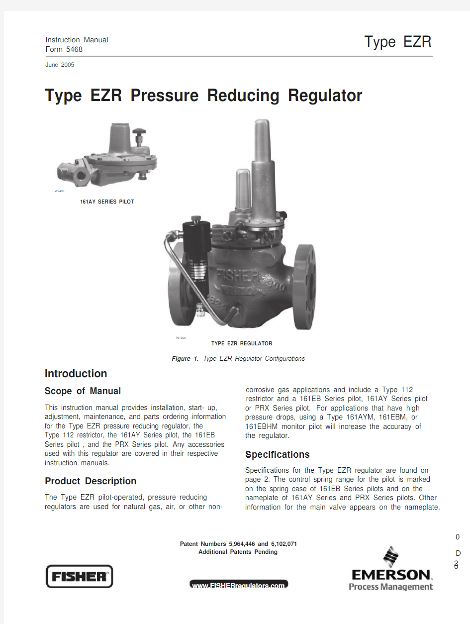
Type EZR Pressure Reducing Regulator
W7430
161AY SERIES PILOT
W7399
TYPE EZR REGULATOR
Introduction
Scope of Manual
Figure 1. Type EZR Regulator Con?gurations
corrosive gas applications and include a Type 112 restrictor and a 161EB Series pilot, 161AY Series pilot
This instruction manual provides installation, start- up, adjustment, maintenance, and parts ordering information for the Type EZR pressure reducing regulator, the Type 112 restrictor, the 161AY Series pilot, the 161EB Series pilot , and the PRX Series pilot. Any accessories used with this regulator are covered in their respective instruction manuals.
Product Description
The Type EZR pilot-operated, pressure reducing regulators are used for natural gas, air, or other non-
or PRX Series pilot. For applications that have high pressure drops, using a Type 161AYM, 161EBM, or 161EBHM monitor pilot will increase the accuracy of the regulator.
Speci?cations
Speci?cations for the Type EZR regulator are found on page 2. The control spring range for the pilot is marked on the spring case of 161EB Series pilots and on the nameplate of 161AY Series and PRX Series pilots. Other information for the main valve appears on the nameplate.
0 Patent Numbers 5,964,446 and 6,102,071
Additional Patents Pending
D
R
2 0
Type EZR Speci?cations
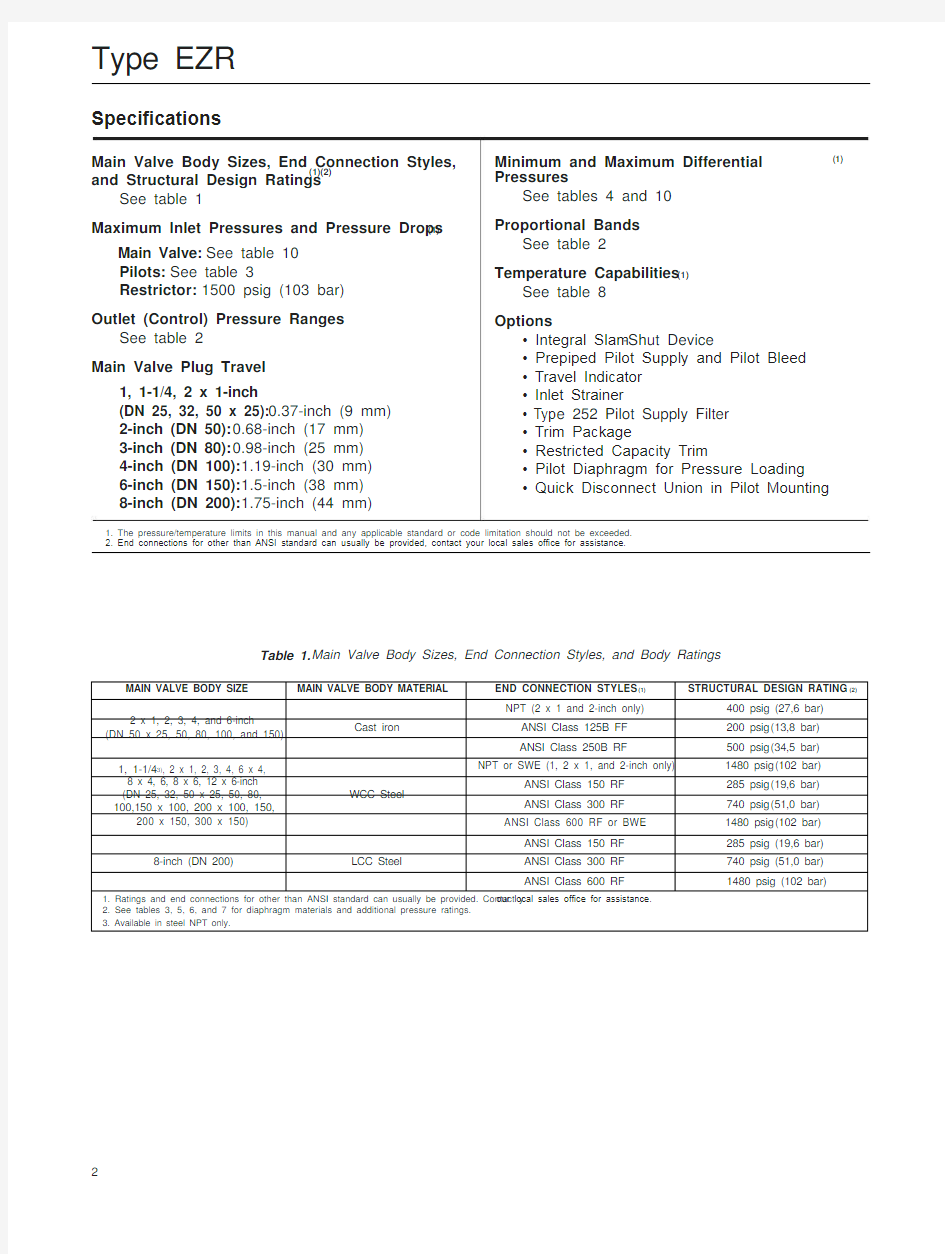
Main Valve Body Sizes, End Connection Styles, and Structural Design Ratings
See table 1
Maximum Inlet Pressures and Pressure Drops(1) Main Valve: See table 10
Pilots: See table 3
Restrictor: 1500 psig (103 bar)
Outlet (Control) Pressure Ranges
See table 2
Main Valve Plug Travel
1, 1-1/4, 2 x 1-inch
(DN 25, 32, 50 x 25): 0.37-inch (9 mm)
2-inch (DN 50): 0.68-inch (17 mm)
3-inch (DN 80): 0.98-inch (25 mm)
4-inch (DN 100): 1.19-inch (30 mm)
6-inch (DN 150): 1.5-inch (38 mm)
8-inch (DN 200): 1.75-inch (44 mm)Minimum and Maximum Differential
Pressures
See tables 4 and 10
Proportional Bands
See table 2
Temperature Capabilities(1)
See table 8
Options
? Integral Slam-Shut Device
? Prepiped Pilot Supply and Pilot Bleed
? Travel Indicator
? Inlet Strainer
? Typ e 252 Pilot Supply Filter
? Trim Package
? Restricted Capacity Trim
? Pilot Diaphragm for Pressure Loading
? Quick Disconnect Union in Pilot Mounting
(1)
1. The pressure/temperature limits in this manual and any applicable standard or code limitation should not be exceeded.
2. End connections for other than ANSI standard can usually be provided, contact your local sales of?ce for assistance.
Table 1.Main Valve Body Sizes, End Connection Styles, and Body Ratings
2
(1)(2)
Type EZR
161A Y SERIES PILOT
161EB SERIES PILOT
TYPE 112 RESTRICTOR
TYPE 252 PILOT
SUPPLY FILTER
B2625_2
MAIN SPRING
DIAPHRAGM AND
PLUG ASSEMBLY W7346
INLET PRESSURE
OUTLET PRESSURE
LOADING PRESSURE
ATMOSPHERIC PRESSURE
2A—Type EZR with Types 161EB Pilot, 112 Restrictor and a 252 Filter
TYPE 252 FILTER
RESTRICTOR
TYPE PRX PILOT
DAMPER
E0790
INLET PRESSURE
OUTLET PRESSURE
LOADING PRESSURE
ATMOSPHERIC PRESSURE
2B—Type EZR with PRX Series Pilot and a Type 252 Filter Schematic
Figure 2.Type EZR Operational Schematic
3
Type EZR
Table 2. Outlet (Control) Pressure Ranges, Proportional Bands, and Pilot Control Spring Information
Table 3. Pilot Pressure Ratings
Principle of Operation
As long as the outlet (control) pressure is above the outlet pressure setting, the pilot valve plug or disk remains closed (?gure 2). Force from the main spring, in addition to inlet pressure bleeding through the Type 112 restrictor (the restrictor is integral in the PRX Series pilots), provides downward loading
pressure to keep the main valve diaphragm and plug assembly tightly shut off.
When the outlet pressure decreases below the pilot outlet pressure setting, the pilot plug or disk assembly opens. Loading pressure bleeds downstream through the pilot faster than it can be replaced through the Type 112 restrictor. This reduces loading pressure on top of the main valve diaphragm and plug assembly and lets the unbalanced force between inlet and
4
loading pressure overcome the main spring force to open the Type EZR diaphragm and plug assembly. As the outlet pressure rises toward the outlet pressure setting, it compresses the pilot diaphragm against the pilot control spring and lets the pilot valve plug or disk close. Loading pressure begins building on the Type EZR diaphragm and plug assembly. The loading pressure, along with force from the main spring, pushes the diaphragm and plug assembly onto the knife edged seat, producing tight shutoff.
Pilot Type Descriptions
Type 161AY —Low-pressure pilot with an outlet pressure range from 6-inches w.c. to 7 psig (15 mbar to 0,48 bar). Pilot bleeds (exhausts) downstream through the sense (control) line.
Table 4.Main Valve Minimum Differential Pressures(1)
Type EZR
Type 161AYM—The monitor version of the Type
161AY pilot. The pilot bleed (exhaust) is isolated from the sense (control) line. This pilot is used in monitoring systems requiring an isolated pilot bleed (exhaust). Type 161EB—High accuracy pilot with an outlet pressure range from 5 to 350 psig (0,34 to 24,1 bar). Pilot bleeds (exhausts) downstream through the sense (control) line.
Type 161EBM—The monitor version of the Type
161EB pilot. The pilot bleed (exhaust) is isolated from the sense (control) line. This pilot is used in monitoring systems requiring an isolated pilot bleed (exhaust). Type 161EBH—The high-pressure version of the Type 161EB pilot with an outlet pressure range from 250 to 700 psig (17,2 to 48,3 bar).
Type 161EBHM—The high-pressure version of the Type 161EBM pilot with an outlet pressure range from 250 to 700 psig (17,2 to 48,3 bar).
Type PRX/120—Outlet pressure range of 7.3 to
609 psig (0,5 to 42 bar). The Type PRX/120 can be used as the pilot on single-stage pressure reducing regulators or as the monitor pilot or as the working pilot in wide-open monitor systems. The PRX has a double diaphragm which provides increased accuracy and sensitivity, an integral restrictor adjustment to allow adjustable opening and closing speeds, and
a damper adjustment to allow adjustments to make
for inlet pressure variability and loading pressure oscillations.
Type PRX/120-AP—Outlet pressure range of 435 to 1160 psig (30 to 80 bar). The Type PRX/120-AP can be used as the pilot on single-stage pressure reducing regulators or as the monitor pilot or as the working pilot in wide-open monitor systems.
Type PRX/125—Identical to the Type PRX/120 except the restriction screw is removed. The Type PRX/125 can only be used as the monitor override pilot on working monitor applications.
Type PRX/125-AP—Identical to the Type PRX/120-AP except the restriction screw is removed. The Type PRX/125-AP can only be used as the monitor override pilot on working monitor applications.
5
Type EZR
BLOCK VALVE BLOCK VALVE INLET OUTLET SUPPLY PRESSURE LINE
B2605_A RESTRICTOR
CONTROL LINE
161 SERIES PILOT
HAND VALVE
ALTERNATE CONTROL LINE
3A—161 Series Single Pilot Installation with Pilot Exhaust into Control Line BLOCK VALVE BLOCK VALVE INLET
SUPPLY PRESSURE LINE
B2605_B
RESTRICTOR
161 SERIES
PILOT
PILOT
EXHAUST
CONTROL LINE
OUTLET
HAND VALVE
ALTERNATE CONTROL LINE 3B—161 Series Single Pilot Installation with Separate Pilot Exhaust Line
BLOCK VALVE BLOCK VALVE
INLET
SUPPLY PRESSURE LINE PRX PILOT PILOT
EXHAUST
CONTROL LINE
OUTLET
HAND VALVE
ALTERNATE CONTROL LINE
3C—Type PRX Single-Pilot Installation with Separate Pilot Exhaust Line
Figure 3.Typical Type EZR Single Installation Schematics
6
Type EZR
Note
For applications requiring extremely tight control, using a Type 161AYM, 161EBM, or 161EBHM monitor pilot will increase the accuracy of the regulator.
Type EZR Installation
!
Personal injury, equipment damage, or leakage due to escaping gas or bursting of pressure-containing parts may result if this regulator is overpressured or is installed where service conditions could exceed the li mits given in Speci?cations on page 2, or where conditions exceed any ratings of the adjacent piping or piping connections.
To avoid such injury or damage, provide pressure-relieving or pressure-limiting devices (as required by the appropriate code, regulation, or standard) to prevent service conditions from exceeding limits. Additionally, physical damage to the regulator could break the pilot off the main valve, causing personal injury and property damage due to escaping gas. To avoid such injury and damage, install the regulator in a safe location.
All Installations
The robust design of the Type EZR allows this regulator to be installed indoors or outdoors. When installed outdoors, the Type EZR does not require protective housing. This regulator is designed to withstand the elements. The powder paint coating protects against minor impacts, abrasions, and corrosion.
When installed indoors, no remote venting is required except on the pilot spring case. This regulator can also be installe d in a pit that is subject to ?ooding by venting the pilot spring case above the maximum possible ?ood level so the pilot setting can be referenced at atmospheric pressure.
1.
Only personnel quali?ed through training and experience should install, operate, and maintain a
regulator. Before installation, make sure that there is no damage to, or debris in, the regulator. Also, make sure that all tubing and piping are clean and unobstructed.
Note
The Type EZR optional inlet strainer is intended to prevent occasional large particles from entering the main valve. If the gas contains continuous particles, upstream ?ltration is recommended.
When using an inlet strainer (key 23), do not use the shim (key 23) and vise versa. 2. A Type EZR regulator may be installed in any orientation, as long as ?ow through the regulator matches the direction of the arrow on the main valve body. However, for easier maintenance, install the regulator with the bonnet up.
When installing a Type EZR trim package in an existing E-body, make sure ?ow is up through the center of the cage and down through the cage slots. In some cases, correct ?ow path is achieved by removing the body from the line and turning it around. If this is done, change the ?ow arrow to indicate the correct direction. Damage may result if ?ow is not in the correct direction. After assembly, check the regulator for shutoff and leakage to atmosphere.
3.
The standard pilot mounting position is as shown in ?gure 1. Other mounting positions are available.
4. Apply a good grade of pipe compound to the male pipeline threads for a screwed body, or use suitable line gaskets for a ?anged body. When installing buttweld end connections, remove trim before welding and make sure to use approved welding practices. Use approved piping procedures when installing the regulator.
A regulator may vent some gas to the atmosphere. In hazardous or ?ammable gas service, vented gas may accumulate and cause personal injury, death, or
prope rty damage due to ?re or explosion. Vent a regulator in hazardous gas service to a remote, safe location away from air intakes or any hazardous location. Protect the vent line or stack opening against condensation or clogging.
7
Type EZR
5. A clogged pilot spring case vent may cause the regulator to function improperly. To prevent plugging (and to keep the spring case from collecting moisture, corrosive chemicals, or other foreign material) point
the vent down, orient it to the lowest possible point
on the spring case or otherwise protect it. Inspect the vent regularly to make sure it has not been plugged.
To remotely vent a spring case, remove the vent and install obstruction-free tubing or piping into the
1/4-inch NPT vent tapping. Provide protection on a remote vent by installing a screened vent cap onto the remote end of the vent pipe. The 161AY Series pilot
has a vent re striction (key 55, ?gure 19) to enhance
low ?ow stability. Do not remove this restriction.
!
To avoid freezeup because of pressure
drop and moisture in the gas, use
antifreeze practices, such as heating the
supply gas or adding a de-icing agent to
the supply gas.
6. As shown in ?gure 3, run a supply pressure line from the upstream pipeline to the restrictor inlet
(use 3/8-inch (9,5 mm) outer diameter tubing or larger). Install a Type 252 pilot supply ?lter upstream of the restrictor, if needed, to keep the supply source from clogging the restrictor or pilot. Inspect and clean this
?lter regularly to make sure it has not been plugged.
7. Install a downstream pressure control line
(as shown in the appropriate view of ?gure 3) to the
pilot control line connection. Connect the other end of the control line at a minimum of 8 to 10 pipe diameters downstream of the regulator, in a straight run of pipe.
Do not place control line connection in a turbulent area, such as in or directly downstream of a swage or elbow. Signi?cant restrictions in the control line can prevent proper pressure registration. When using a hand valve, it should be a full ?ow valve, such as a full port ball valve. With a Type 161EBM, 161EBHM or 161AYM pilot run a downstream exhaust bleed line to the downstream bleed line connection in the pilot body assembly.
8. Good piping practices usually require swaging
up to larger downstream piping to obtain reasonable downstream ?uid velocity.
Wide-Open Monitor Installations
1. Follow the procedures in the All Installations section, and then continue with step 2 of this section.
2. Pilot supply for the downstream monitoring regulator must be obtained between the two regulators as shown in ?gure 4. With this arr angement, the downstream monitoring regulator diaphragm changes position with every load change. For sizing purposes, add the minimum differential pressure for each regulator together to establish the required pressure drop across the station. System lockup pressure is equal to the setpoint of the working regulator pilot when a Type 161EBM or a Type 161AYM is used on an upstream regulator, otherwise lockup pressure is equal to monitor pilot lockup pressure.
Working Monitor Installations
On working monitor installations, the working monitor regulator is always upstream and acts as a ?rst-stage regulator through the working pilot during normal operation. This arrangement allows the working monitor’s performance to be observed at all times. Then, should the second-stage regulator fail open, the working monitor regulator assumes the entire pressure reduction function of the system through the monitoring pilot.
Use the following procedure when installing a working monitor system.
1. Follow the procedures in the All Installations section, and then continue with step 2 of this section.
2. Pilot supply pressure for the downstream
Type EZR regulator must be made directly upstream of the Type EZR using intermediate pressure.
3. Signi?cant restric tions in the control line can prevent proper pressure registration. Connect the control line a minimum of 8 to 10 pipe diameters downstream of the regulator in a straight run of pipe. Do not make the control line connection in a turbulent area, such as in or directly downstream of a swage or elbow. When used, a hand valve should be a full ?ow valve such as a full port ball valve.
4. Table 9 gives the spread between normal distribution pressure and the minimum pressure at which the monitor pilot can be set to take over if the working regulator fails open.
5. Table 4 shows the minimum differential pressure requirements across an individual regulator. Because this application uses a ?rst-stage and second-stage pressure reduction, add the minimum differential pressure for each regulator together to establish the required pressure drop across the station. Do not exceed maximum pilot ratings given in table 3.
EZR/PRX Working Monitor
On working monitor installations, the working monitor regulator is always upstream and acts as a ?rst-stage
8
Type EZR
INLET BLOCK VALVE UPSTREAM REGULATOR DOWNSTREAM
REGULATOR
BLOCK VALVE
OUTLET
SUPPLY PRESSURE LINE
B2605_C
RESTRICTOR
161 SERIES PILOT
SUPPLY
PRESSURE
LINE
PILOT RESTRICTOR
EXHAUST
161 SERIES
PILOT
CONTROL LINE
CONTROL
LINE
ALTERNATE
HAND VALVE
HAND
VALVE
4A—161 Series Wide-Open Monitoring System Installation (Upstream or
Downstream)
CONTROL LINE
INLET BLOCK VALVE MONITOR REGULATOR WORKING
REGULATOR
BLOCK VALVE
OUTLET
SUPPLY
PRESSURE LINE RESTRICTOR
161 SERIES
MONITOR PILOT
SUPPLY
PRESSURE
LINE
CONTROL LINE
161 SERIES WORKING
PILOT
RESTRICTOR
CONTROL LINE
161 SERIES
PILOT
ALTERNATE
HAND VALVE
HAND
VALVE
B2605_D
BLOCK VALVE 4B—161 Series Working Monitoring System Installation
UPSTREAM REGULATOR REGULATOR
CONTROL LINE
BLOCK VALVE
INLET OUTLET
SUPPLY PRESSURE LINE
PRX PILOT
SUPPLY
PRESSURE
LINE
PILOT
EXHAUST
PRX
PILOT
CONTROL LINE
HAND
VALVE
HAND
VALVE
ALTERNATE
CONTROL LINE
4C—Type PRX Wide-Open Monitoring System Installation (Upstream or Downstream)
MONITOR REGULATOR REGULATOR
BLOCK VALVE
INLET OUTLET
SUPPLY PRESSURE LINE L
S
B
A
L
B
(1)
SUPPLY
HAND
VALVE
(1) PLUGGED PRX-120
WORKING PILOT
PRX-125
MONITOR PILOT
PRESSURE
LINE
CONTROL LINE
ALTERNATE
CONTROL LINE
HAND
VALVE 4D—Type PRX Working Monitor System Installation
Figure 4.Typical Type EZR Monitoring System Installation Schematics
9
DOWNSTREAM
WORKING
A
S
Type EZR
PRX/120 WORKING PILOT
PRX/125
MONITOR PILOT
(NO RESTRICTOR SCREW)
PRX/120
PILOT
S
L
A B S
L
A
B
S
L
A
B
FILTER (PLUGGED)
FILTER
INLET
INLET PRESSURE
OUTLET PRESSURE
LOADING PRESSURE
INTERMEDIATE PRESSURE
ATMOSPHERIC PRESSURE
INTERMEDIATE
Figure 5.EZR-PRX-PRX Working Monitor Schematic
OUTLET
regulator through the working pilot during normal operation. This arrangement allows the working The pilot supply pressure connection for the downstream Type EZR regulator must be directly
monitor’s performance to be observed at al l times. Then, should the second-stage regulator fail open,
the working monitor regulator assumes the entire pressure reduction function of the system through the monitoring pilot. Use the following procedure when installing a working monitor system.
As shown in ?gure 5, run a supply pressure line
(use 3/8-inch (9,5 mm) outer diameter tubing or larger) from the upstream pipeline to the inlet (Port S) of
the upstream PRX-120 pilot. Install a Type 252 pilot supply ?lter upstream of the pilot, if nee ded, to keep
the supply source from clogging the restrictor in the pilot. Inspect and clean this ?lter regularly to make
sure it has not been plugged.
Connect the loading port (Port L) of the upstream
PRX-120 pilot to the bonnet of the upstream EZR regulator. Connect the ―B‖ port of the upstream
PRX-120 pilot to the ―S‖ port of the upstream PRX-125 pilot. Connect the ―A‖ port (located on the underside
of the pilot) of the upstream PRX-120 pilot to the intermediate pressure between the ?rst and s econd EZR regulators as shown in ?gure 5.
The ―L‖ port of the upstream PRX-125 pilot is plugged. Connect the ―B‖ port of upstream PRX-125 pilot to the intermediate pressure between the ?rst and second EZR regulators.Connect the ―A‖ port of upstream PRX-125 pilot downstream of both regulators.upstream of the Type EZR using intermediate pressure and connected to the ―S‖ port of the downstream
PRX-120. Install a Type 252 pilot supply ?lter upstream of the pilot, if needed, to keep the supply source from clogging the restrictor in the pilot. Inspect and clean this ?lter regularly to make sure it has not been plugged. Connect the loading port (Port L) of the downstream PRX-120 pilot to the bonnet of the downstream
EZR regulator. Connect the ―A‖and ―B‖ ports of the downstream PRX-120 pilot to downstream pressure. Signi?cant restrictions in control lines can prevent proper pressure registration. Connect the control line
a minimum of 8 to 10 pipe diameters downstream of
the regulator in a straight run of pipe. Do not make
the control line connection in a turbulent area, such as in or directly downstream of a swage or elbow. When used, a hand valve should be a full ?ow valve such as full port ball valve.
Table 4 shows the minimum differential pressure requirements across an individual regulator. Because this application uses a ?rst-stage and second-stage pressure reduction, add the minimum differential pressure for each regulator together to establish the required pressure drop across the station. Do not exceed maximum pilot ratings given in table 3.
10
Type EZR
Startup and Adjustment
Note
Table 10 show maximum inlet and differential press ures for speci?c
constructions. Use pressure gauges to monitor inlet pressure, outlet pressure, and any intermediate pressure during startup.
Startup
for Both Single -Re gula tor
and Monitoring Installations
1.
Make sure all block and vent valves are closed.
W4559_1
Figure 6. Restrictor Adjustment
2.
Back out the pilot adjusting screw(s).
3.
For easy initial startup, set the restrictor to the START position. For future startups, the restrictor can be left in the desired run position.
4.
SLOWLY OPEN the valves in the following order:
a. Pilot supply and control line valve(s), if used
b. Inlet block valve
c. Outlet block valve
5.
For a 161 Series pilot with Type 112 restrictor, turn the restrictor(s) to the RUN position (2) or to the desired run position. For a PRX Series pilot, turn the restrictor screw 1 turn counterclockwise from fully seated (turn restrictor fully clockwise then 1 turn counterclockwise) and the damper screw fully counterclockwise (or to the desired run position (2)).
6.
For a single regulator, set the pilot to the
desired outlet (control) pressure according to the pilot adjustment procedure.
For a wide-open downstream monitor installation, adjust the upstream working pilot until intermediate pressure is higher than the desired setpoint of the monitor pilot. Adjust the downstream monitoring pilot to the desired monitoring takeover pressure. Reduce the upstream pilot to the normal outlet pressure setting. For a wide-open upstream monitor installation, adjust the downstream working pilot to a setpoint higher than the setpoint of the monitor pilot. Adjust the upstream monitoring pilot to the desired monitor takeover pressure. Reduce the downstream pilot setting to normal outlet pressure setting.
For a working monitor installation, adjust the set-point of the upstream monitor pilot to the desired maximum pressure. Adjust the upstream working pilot to the desired intermediate pressure setting. Adjust the
downstream pilot to a pressure setting slightly above the upstream monitor pilot pressure setting. Adjust the upstream monitor pilot to its desired setpoint. The setpoint of the monitor pilot should be adjusted at least to the guidelines shown in table 9. The maximum may be greater. Then, establish ?nal desired downstream pressure by adjusting the downstream working regulator pilot.
Pilot Adjustment
For 161 Series pilots, remove the pilot closing cap (key 16, ?gure 19 or key 22, ?gure 20) and, on 161EB Series only, loosen the locknut (key 12, ?gure 19). Turn the adjusting screw (key 11, ?gure 19 or key 35, ?gure 20) into the spring case (key 2, ?gure 19 or key 3, ?gure 20) to increase the downstream pressure. Turn the adjusting screw out of the spring case to decrease the downstream pressure.
For PRX Series pilots (?gure 24), loosen locknut
(key 2) and turn the adjusting screw into the spring case to increase (or out of the spring case to decrease) the downstream pressure. When the required downstream pressure is maintained for several minutes, tighten the locknut to lock the adjusting screw in position
(161EB Series only) and replace the pilot closing cap.
Type 112 Restrictor Adjustment
The Type 112 restrictor controls the regulator’s
proportional band (droop) and speed of response. The restrictor can be used to ?ne tune the regulator for maximum performance by decreasing the restrictor setting for tighter control (increased opening speed, decreased closing speed); or increasing the restrictor setting for maximum stability (decreased opening speed, increased closing speed). A lower setting also provides a narrower proportional band for better accuracy. The START position has the largest ?ow, is
11
Type EZR
most stable, and easiest for startup, however, using
t he START position is not necessary. The ―0‖ setting has the smallest (minimum) ?ow passage; at no point of rotation will the Type 112 restrictor be completely shut off. After initial adjustment, the restrictor does not need to be adjusted for maintenance or startup.
Pilot Adjustment – (For Low Flow Applications Only)
For s table, low-flow operat ion, ot her considerations besides pilot s ettings should also be addressed.
Ins tallation of an over-sized regulator may mak e
low-flow operation difficult. When possible, a
smaller-sized EZR s hould be ins talled. During design of a regulat or inst allation, the downstream piping volume s hould be maximiz ed. Control lines should not be located in or near piping sections
that may experience turbulent flow, such as elbows
or swages. Larger diameter control lines are also recommended in low-flow conditions. The larger control lines are less restrictive and will reduce pilot
ex haust bleed backpres sure to the pilot that may
caus e instability. Separate s ense and exhaust lines may als o help at low flow conditions. This feature
is prov ided on the PRX s eries,161M, 161HM,
161EBM, 161EBHM, and 161AYM pilots. Control
line taps should be located in straight pipe; several pipeline diamet ers (8-10 of largest piping on outlet) downs tream of the regulator. These guidelines
are not mandatory but have been us ed to improv e station stability at low flow in some systems. Shutdown for Both Single-Regulator and Monitoring Installations
Table 5.161 Series and 161EB Series Pilot
Adjustment Recommendations
Table 6.161AY/161AYM Pilot Adjustment Recommendations Table 7.PRX Pilot Adjustment Recommendations
!
If pilot supply pressure is shut down
?rst, the downstream system may be
subjected to full inlet pressure.
1. If the pilot setting must be disturbed, be sure to keep
some tension on the spring. This will prevent trapping inlet pressure during blow down.
2. Close the valves shown in ?gure 5 or 6, in and if used (3) control line valve(s).
3. Open the vent valves to depressurize the system. 12
Type EZR Table 8.Diaphragm Material Selection Information
Gas Temperature
(for lower temperatures
contact your local Sales
Of?ce or Representative) General Applications
Heavy Particle Erosion Natural Gas With:
Up to 3% aromatic hydrocarbon content(2)
3 - 15% aromatic hydrocarbon content(2)
15 - 50% aromatic hydrocarbon content(2)
sul?de or sour gas)
Up to 3% ketone
Up to 10% alcohol
Up to 3% synthetic lube
17E68
NITRILE (NBR)
-20° to 150°F (-28° to 66°C)
Best for cold temperatures.
Fair
Good
Poor
Not recommended
Good
Fair
Good
Fair
17E97
NITRILE (NBR)
0° to 150°F (-17° to 66°C)
Best for high pressure conditions, i.e.
transmission service or high pressure
industrial service.It is also the best for
abrasive or erosive service applications.
Excellent
Excellent
Good
Poor
Good
Fair
Good
Fair
17E88
FLUOROELASTOMER (FKM)
0° to 250°F (-17° to 121°C)(1)
Best for natural gas having aromatic
hydrocarbons.It is also the best for
high temperature applications.
Good
Excellent
Excellent
Excellent
Good
Fair
Fair
Good
1. For differential pressures above 400 psig (27,6 bar) diaphragm temperature is limited to 150°F (66°C).
2. The aromatic hydrocarbon content is based on percent volume.
Table 9. Type EZR Working Monitor Performance
13 Up to 3% H S (hydrogen
Type EZR
Table 10.Main Valve Maximum Pressure Ratings, Diaphragm Selection Information, and Main Spring Selection(1)
14
Type EZR
PILOT SUPPLY CONNECTION: 1/4-INCH NPT PIPE CONNECTS TO UPSTREAM PILOT SUPPLY TAP
LOADING CONNECTION: 1/4-INCH NPT PIPE CONNECTS
TO TYPE EZR DIAPHRAGM LOADING PORT
OUTLET CONNECTION: CONNECTS TO
PILOT INLET CONNECTION
11B5004-A
TYPE 112
OPTIONAL LOADING CONNECTION:
1/4-INCH NPT NORMALLY PLUGGED
CONTROL LINE CONNECTION:
1/2-INCH NPT PRESSURE
REGISTRATION ONLY. USE
3/8-INCH O.D. TUBING OR
LARGER FOR CONTROL LINE
INLET 3/4-INCH NPT
CONNECTS TO 1/4-INCH NPT
TYPE 112 OUTLET
B2609
TYPE 161AY CONTROL LINE CONNECTION:
3/4-INCH NPT PRESSURE
REGISTRATION AND PILOT
BLEED (EXHAUST). USE
3/4-INCH PIPE MINIMUM FOR
CONTROL LINE
INLET 3/4-INCH NPT
CONNECTS TO
1/4-INCH NPT
TYPE 112 OUTLET
TYPE 161AYM
PILOT BLEED (EXHAUST)
CONNECTION: 3/4-INCH NPT. USE
1/2-INCH PIPE MINIMUM FOR
BLEED (EXHAUST) LINE
INLET 1/4-INCH NPT CONNECTS TO 1/4-INCH NPT TYPE 112 OUTLET
21B5005-A
1/4-INCH NPT
NORMALLY PLUGGED
INLET 1/4-INCH NPT
CONNECTS TO
1/4-INCH NPT TYPE
112 OUTLET
CONTROL LINE CONNECTION:
1/4-INCH NPT PRESSURE
REGISTRATION AND PILOT
BLEED (EXHAUST). USE
3/8-INCH O.D. TUBING LARGER
FOR CONTROL LINE
TYPES 161EB AND 161EBH
CONTROL LINE CONNECTION:
1/4-INCH NPT PRESSURE
REGISTRATION ONLY. USE
3/8-INCH O.D. TUBING OR
LARGER FOR CONTROL LINE
PILOT BLEED (EXHAUST)
CONNECTION: 1/4-INCH NPT USE
3/8-INCH O.D. TUBING OR LARGER
FOR BLEED (EXHAUST) LINE
TYPES 161EBM AND 161EBHM
Figure 7.Pilot Port Function and Connection Sizes
15
Type EZR
Maintenance
Regulator parts are subject to normal wear and must be inspected periodically and replaced as necessary. Due to the care Fisher takes in meeting all manufacturing requirements (heat treating,
dimensional tolerances, etc.), use only replacement parts manufactured or furnished by Fisher. Also, when lubrication is required, use a good quality lubricant and sparingly coat the recommended part. The frequency of inspection and parts replacement depends upon the severity of service conditions, applicable codes and government regulations, and company inspection procedures. Table 9 lists various regulator problems and possible solutions for them.
STYLE (IMPRINT) MATERIAL
(IMPRINT)
MATERIAL (INK MARK)
1 1
1 1
11
1
1
STYLE (INK MARK) (MA Y BE IN EITHER
LOCATION)
DOME
IDENTIFICATION
STYLE (INK MARK) (MA Y BE IN EITHER
LOCATION)
Type EZR Main Valve Trim Parts
Instructions are given for complete disassembly and assembly. The main valve may remain in the pipeline during maintenance procedures. Key numbers are referenced in ?gures 14 through 18.
Figure 8. Diaphragm Markings
Table 11. Diaphragm Imprint Codes
Avoid personal injury or damage to property from sudden release of pressure or uncontrolled gas or other process ?uid. Before starting to disassemble, carefully release all pressures according to the shutdown procedure. Use gauges to monitor inlet and outlet pressures while releasing these pressures.
Converting a Fisher E-Body to Type EZR:
Remove all trim parts from the main valve and clean the body interior. Then follow procedure in Assembly section to convert a Fisher E-body to a Type EZR.
When installing a Type EZR trim package make sure ?ow is up through the c enter of the cage and down through the cage slots. In some cases, correct ?ow path is achieved by removing the body from the line and turning it around. If this is done, change the ?ow arrow to indicate the correct direction. Damage may result if ?o w is not in the correct direction. After assembly, check the regulator for shutoff and leakage to atmosphere.
Disassembly
Disassembly of Type EZR:
1.
Shut down, isolate, and depressurize the main valve and pilot.
2.
Remove the cap screws (key 3). Lift up and remove the bonnet (key 2) from the body (key 1).
3. Remove the diaphragm and plug assembly (key 9) and bonnet O-ring (key 28). For 2x1-inch (DN 50 x 25) sizes, use a screwdriver to remove the upper adapter (key 131).
4.
Pull out the cage (key 7), O-ring (key 8), and inlet strainer or strainer shim (key 23) (if no strainer). For 2x1-inch (DN 50 x 25) sizes, remove the lower adapter (key 132).
5.
Clean parts and replace if necessary. To change the O-ring (key 121) on a 6-inch cage with attached restrictor plate (key 71), remove cap screws (key 126).
Assembly
1.
Install the inlet strainer or shim (key 23) into the body (key 1).
16
Type EZR
Table 12. Troubleshooting Guide
Note
When installing in a vertical orientation, apply lubricant to the bottom of the inlet strainer or strainer shim (key 23) to help hold parts in place while installing cage. 2.
Lightly lubricate and install the cage O-ring (key 8).
3.
Apply lubricant lightly to all O-rings or the mating part before installing them.
4.
Install the cage (key 7) and lightly lubricate and install the bonnet O-ring (key 28).
To assemble a 6-inch (152 mm) cage with attached restrictor plate (key 71), lightly lubricate the O-ring
(key 121) and place it on the restrictor plate. Secure the
cage to the restrictor plate with the cap screws (key 126),
using a torque of 10 to 12 foot-pounds (14 to 16 N?m). For 2x1-inch (DN 50 x 25) sizes, the lower adapter
(key 132) must be assembled on the cage before
placing in the body. Lightly lubricate the lower
adapter O-rings (keys 121 and 67) and place the
lower adapter on a ?at surface. Then press the cage
down into the lower adapter.
5.
Lubricate the top and bottom of the outer edge (bead area) of the diaphragm and place diaphragm and plug assembly (key 9) on the cage (key 7). For 2x1-inch (DN 50 x 25) sizes, the upper adapter (key 131) must be placed on the cage before the bonnet (key 2). Lightly lubricate the upper adapter O-ring (key 133) and then press the upper adapter onto the cage.
6. If travel indicator was removed, lightly lubricate the travel indicator assembly threads and screw it into the bonnet (key 2). See Travel Indicator Assembly Maintenance for maintenance.
7.
Install the bonnet (key 2) in proper orientation. Make sure to use a Type EZR
bonnet. The Type EZR bonnet is NOT interchangeable with other Fisher E-body bonnets. Installing an improper bonnet can result in stem assembly breakage and unit failure. The bonnet can be identi?ed by the EZR markings on the top.
17
Type EZR
W7394FLANGED
LOCKNUT
(KEY 13)
BOTTOM PLUG
(KEY 11)
O-RING
(KEY 10)
DIAPHRAGM
(KEY 9)
O-RING
(KEY 70)
O-RING
(KEY 14)
TOP PLUG
(KEY 5) Figure9.Diaphragm and Plug Assembly Components
8. Lubricate cap screws (key 3) and secure the bonnet (key 2), using an even criss-cross pattern. It may be necessary to push down on bonnet to start cap screws. Tighten cap screws to proper torque (see table 13).
Diaphragm and Plug Assembly Maintenance
The diaphragm and plug assembly can be replac ed as a s ingle unit (a diaphragm cartridge), or individual c omponents within the ass embly c an be replaced. When replacing individual components, inspect eac h c omponent for damage and wear,
and replace parts as needed. Key numbers for the following ass embly and disassembly procedure are referenced in ?gures 9 and 14.
1. Place a screwdriver or similar tool through the hole in the top plug (key 5).
2. Remove the ?ange d locknut (key 13) from the bottom plug (key 11). This loosens the entire assembly.
Note
On 1, 1-1/4, and 2 x 1-inch (DN 25, 32,
and 50 x 25) bodies, remove the socket
head screw (key 129) and lock washer
(key 130) from the bottom plug.
3. Remove the bottom plug (key 11) and the bottom plug O-ring (key 10).
4. Remove the diaphragm (key 9).
5. Remove the top plug O-rings (keys 14 and 70).
6. Check all components for damage or wear and replace as necessary.
7. When reassembling, be sure to lubricate all O-rings before installing.
8. Hold the top plug (key 5). Place the parts on the top plug in the following order:
? O-Ring (key 14)
? O-Ring (key 70)
? Diaphragm (key 9)
? O-Ring (key10)
? Bottom Plug (key 11)
? Flanged Locknut (key 13)
9. Reassemble in the reverse order. Tighten ?ange locknut (key 13) to proper torque (see table 13). Travel Indicator Assembly Maintenance Travel indicator assembly key numbers are referenced in ?gures 10, 14, and 18. The indicator assembly
can be removed and installed without removing the bonnet (key 2) from the body (key 1). Travel indicator maintenance is performed for two reasons:
a. When damaged or worn parts need replacing.
b. When travel indicator is removed and replaced with a travel indicator plug assembly.
!
Avoid personal injury or damage
to property from sudden release
of pressure or uncontrolled gas or
other process ?uid. Before starting
to disassemble, carefully release all
pressures according to the shutdown
procedure. Use gauges to monitor inlet,
loading, and outlet pressures while
releasing these pressures.
1. Remove the indicator protector (key 22, ?gure 14) and indicator cover (key 21).
2. Remove the ?rst hex nut (key 4) and the indicator washer (key 20).
18
Type EZR INDICATOR FITTING MAIN SPRING
INDICATOR COVER (KEY 21)HEX NUTS
(KEY 4)
(KEY 19)
O-RING
(KEY 18)
UPPER SPRING
SEAT (KEY 17)(KEY 12)
INDICATOR STEM
(KEY 15)
W7400_1INDICATOR INDICATOR
O-RING (KEY 6)
BACKUP
RINGS
(KEY 16)
WASHER (KEY 79)
(6-INCH SIZE ONLY)
WASHER (KEY 20)
Figure 10.Travel Indicator Parts
Table 13.Torque Values
3. Unscrew the second hex nut (key 4) to the top of the indicator stem (key 15). Do not remove.
4. Use a wrench to remove indicator ?tting (key 19).
5. Lift out travel indicator assembly. If replacing travel indicator with travel indicator plug, skip to step 9.
6. Compress the main spring (key 12). Remove the second hex nut (key 4). Parts will separate easily when the hex nut is removed.
7. Slide the indicator stem (key 15) out of the indicator ?t ting (key 19). The main spring (key 12) and upper spring seat (key 17) will be free.
8. If necessary, use the indicator stem (key 15) to pry the backup rings (key 16) and O-ring (key 18) out of the indicator ?tting (key 19).
9. Check the indicator ?t ting O-ring (key 6). Lubricate and replace if necessary.
10. To replace travel indicator parts, lubricate all
O-rings, backup rings, and threads. To reassemble, hold the indicator stem (key 15) and place the parts
on the stem in the following order:
?Washer (key 79 for 6-inch (DN 150) size only)
? Main Spring (key 12), small end ?rst
? Upper Spring Seat (key 17), make sure to place
the large end toward the spring
? First Backup Ring (key 16)
? O-Ring (key 18)
? Second Backup Ring (key 16)
? Indicator Fitting (key 19), the backup rings (key 16) and O-ring (key 18) should slide into the indicator ?tting and the small end of the upper spring seat
(key 17) should slide into the indicator ?tting.
? First Hex Nut (key 4)
? Indicator Washer (key 20)
? Second Hex Nut (key 4)
Install the indicator ?tting (key 19) into the bonnet (key 2, ?gure 14), tighten to the proper torque
(see table 13).
To set the travel indicator, hold the indicator cover (key 21) next to the indicator ?tting (key 19). Scre w the hex nuts (key 4) and the indicator washer (key 20) down on the indicator stem (key 15) until the washer is even with the lowest marking on the indicator cover. Lightly lubricate the indicator cover threads and install. Replace the indicator protector (key 22).
To replace the travel indicator with the non-travel indicator option, place the main spring (key 12) into the bonnet. Install the indicator plug (key 19) and tighten to proper torque (see table 13).
19
Type EZR
161EB Series Pilots (?gure 19)
Note
This procedure covers all 161EB Series pilots. Types 161EB and 161EBM rated for outlet pressure settings over
200 psig (13,8 bar) and all Types 161EBH and 161EBHM require a diaphragm limiter (key 10). Types 161EB and
161EBM pilots rated for outlet pressure settings under 200 psig (13,8 bar) do not require a diaphragm limiter.
Trim Parts
1. As shown in ?gure 11, remove the body plug (key 3) to let the plug spring (key 6), and valve plug (key 4) drop freely from the body.
2.
Inspect the removed parts and body plug O-ring (key 15), replace as necessary, and make sure the plug seating surfaces are free from debris.
3.
Sparingly apply lubricant to the body plug O-ring (key 15) and the threads of the body plug (key 3). Install the body plug O-ring over the body plug.
4.
Stack the plug spring (key 6), and valve plug (key 4) on the body plug (key 3). Install the body plug with stacked parts into the body (key 1).
Diaphragm Parts
1. Remove the closing cap (key 16), loosen the locknut (key 12), and back out the adjusting screw (key 11) until compression is removed from the control spring (key 9).
2.
Remove the machine screws (key 13, not shown) and separate the spring case (key 2) from the body (key 1). Remove the control spring seat (key 8), the control spring (key 9). If used, remove the diaphragm limiter (key 10) and inspect the diaphragm limiter O-ring (key 23). Replace if necessary.
3.
Remove the diaphragm assembly (key 7) and inspect the diaphragm.
4.
On Type 161EBM and Type 161EBHM pilots, inspect the stem guide seal assembly (key 19) and, if damaged, replace the complete assembly. Inspect the outer O-ring (key 22) and replace if necessary.
5.
Install the diaphragm assembly (key 7) and push down on it to see if the valve plug (key 4) strokes smoothly and approximately 1/16-inch (2 mm).
W4570-1
Figure 11. 161EB Series Pilot Trim Removal/Installation
6. Stack the control spring (key 9), the control spring seat (key 8), and, if used, the diaphragm limiter (key 10) and O-ring (key 23) on the diaphragm assembly (key 7). If used, make sure the diaphragm limiter is installed beveled side up on Types 161EB and 161EBM pilots with 200 to 350 psig (13,8 to 24,1 bar) outlet pressure range. Lightly apply lubricant to the control spring seat.
7. Install the spring case (key 2) on the body (key 1) with the vent (key 18) properly oriented. Make sure the vent is not directly over inlet or outlet piping due to possible icing. Install the machine screws (key 13, not shown), using a crisscross pattern, torque them to 5 to 7 foot-pounds (7 to 9 N?m) for stainless steel bodies and 2 to 3 foot-pounds (3 to 4 N?m) for aluminum bodies. Lubricate the adjusting screw threads.
8.
When maintenance is complete, refer to the Startup and Adjustment section to put the regulator back into operation, and adjust the pressure setting. Tighten the locknut (key 12), replace the closing cap gasket (key 17) if necessary, and install the closing cap (key 16).
161A Y Series Pilots (?gure 20) Body Area
Use this procedure to gain access to the disk
assembly, ori?ce and body O -ring. All pressure must be released from the diaphragm casing, and the disk assembly must be open, before these steps can be performed.
1.
Remove the cap screws (key 2) and separate the diaphragm casing (key 4) from the body (key 1).
2.
Remove body seal O-ring (key 11) and the backup ring (key 50). Inspect the body seal O-ring and replace if necessary.
20
变压器基础知识 第一章变压器的概述
一. 变压器的用途 在各种电气设备中,往往需要不同的电压电源。如我们日常生活的照明用电,家用电器的电压一般都为220V,而各种动力的电压是380V,而线路的电压一般为:6、10、35、110、220、500KV的电压。 这些称为供电系统。3KV以上的称为高压系统。现代化的工业,广泛采用了电力为能源。电能是由水电站、发电厂的发电机转化来的,发电机所发送来的电力根据输电距离将按照不同的电压等级传输出去,这种传输需一种特殊的专门设备。这种设备就是我们熟悉的电力变压器。 变压器在输配电系统中有着很重要的地位,要求它能安全可靠的运行。当变压器出现故障或损坏,将造成大面积的停电。随着技术的发展,工农业生产需要,变压器在很多的领域也广泛的应用。如,根据需要配套的冶炼用的电炉变压器、电解化工用的整流电压器、铁路电力机车用的牵引变压器……等很多。 二. 变压器的分类 按用途分类: 2.1电力变压器:这是目前工农业生产上广泛使用的变压器,它主要用途是为了输配电系统上使用的 变压器。目前电力变压器形成了系列,已经大批量生产。 按容量和电压等级分成以下类别: Ⅰ、Ⅱ类 10~630 KVA Ⅲ类 800~6300 KVA Ⅳ类 8000~63000 KVA Ⅴ类 63000 KVA以上 按电压所用和发电厂的用途不同可分为: 1.降压变压器; 2.升压变压器; 3.其中低压为400伏的降压变压器称为配电变压器。 电能的输配电过程 首先发电厂发电机发出电能,电压一般是6.3或10.5KV,这样低的电压要输送几百公里以外的 地区是不可能的。所以要将电压升高到38.5、121、242、500KV以后再输出去。这样高的电压到 (把电压降为38.5或110KV)和二次变电所(降为10.5或6.3KV)供电区域后还要经过一次变电所, 变压,再把电能直接送到用户区,经过附近的配电变压器降压为(一般为400V)以供工厂或住户 使用。 2.2电炉变压器:
燃气调压撬操作规程 新疆新捷 编制:新疆新捷股份有限公司 博州城市燃气分公司
生产运行部 日期:2016年8月10日
一、(HYTJ-2000 HYTJ-1000) 1.1、运行前 1.将拖车与卸车柱用高压胶管连接好,给调压撬换热器加防冻液,加臭液加到液位计的2/3处。 2.检查调压撬各阀门是否关闭,气路阀门关闭,水路阀门打开。 3.将控制台的电源合上,电加热器在冬季为加热状态,夏季为自动状态,紧急切断阀按钮打在自动状态。 4.将调压撬内所有压力表的底阀打开,并且打开放散阀的底阀,气动切断阀应在开启状态。 5.检查流量计工作是否正常,传输数据是否一致。 1.2、运行 1.当换热器中的温度上升到60℃左右时,慢慢打开卸车柱上高压球阀,并打开调压撬进气阀,使压缩天然气进入到调压撬中并检查调压器仪表风是否工作正常,无漏气。 2.观察进口压力表的读数,待压力稳定后缓慢打开其中一路的高压球阀,另一路上的高压球阀处于关闭状态。 3.压缩天然气经高压球阀、进入一级换热器中,流经盘管的高压天然气通过吸收换热器中热水的热量而升温,
升温后的压缩天然气从一级换热器中出来后进入到过滤器中,过滤后的天然气直接进入到一级调压器中。 4.调节调压器到出口压力(顺时针为将压力调低,逆时针为将压力调高)。观察压力表的读数,调整调压器的出口压力至1.3-1.5MPa,减压后的天然气进入到二级换热器中。 5.在二级换热器中,盘管内的天然气通过吸收热水中的热量而再次升温,升温后的天然气从二级换热器中出来后进入到二级调压器中。 6.经二级调压器调压到0.2-0.3MPa(顺时针为将压力调低,逆时针为将压力调高),打开二级调压器后的碟阀,燃气进入到流量计量系统中。 7.先经过滤器过滤后,再进入到流量计中,经计量后天然气进入到出口管道中。流量计与加臭机用导线连接,加臭机根据当时的流量自动调节加臭量或手动设置加臭量。 8.当使用的一路出现故障时,打开另一路备用管线,操作方法同上。关闭有故障的一路前的高压球阀。保证设备不间断供气。 9.当一级后的压力和出口压力超过压力设定值时,进口处的气动紧急切断阀会自动切断主回路的气源,以保证设备的安全。
产品简介 LSA-2P16YB,LSA-2P25YB,LSA-2P40YB,LSA-H2P10XYB,单相交流半波调压模块 产品详细信息 LSA-2P16YB,LSA-2P25YB,LSA-2P40YB,LSA-H2P10XYB,单相交流半波调压模块LSA-H2P25XYB,LSA-H2P45XYB,LSA-H2P65XY B,LSA-H2P85XYB,
①、电位器手动控制方式:按图示,电位器中间端接到模块cont端,电位器另两端分别接到模块com端和+5V端。+5V电压由模块本身
内部产生,无须外部提供,只配合手控电位器用,不作它用,所选用的电位器阻值在2-10KΩ间。当控制端cont从0-5Vdc改变时,交流负载上的电压从0伏到最大值线性可调,cont端电压越高,模块输出越大。 ②、0-5Vdc控制方式:按图示,可接受单片机等的0-5Vdc模 拟信号,控制输入正极接cont端、负极接com端,模块内部cont 端相对com端的输入阻抗大于30KΩ。当控制端cont从0-5Vdc 改变时,交流负载上的电压从0伏到最大值线性可调,其中cont 在0-0.7Vdc左右时为全关闭区域,可靠关断整个电路的输出; cont在0.7Vdc-4.3Vdc左右为可调区域,即随着控制电压的增大,移相角α从180°到0°线性减小,导通角增大,交流负载上的电压从0伏增大到最大值;cont在4.3Vdc-5Vdc左右时为全开通区域,交流负载上的电压为最大值(接近电网电压)。 ③、0-10Vdc控制方式:按图示,可接受PLC等的0-10Vdc 模拟信号,模块内部0-10Vdc端相对com端的输入阻抗大于15K Ω。 ④、4-20mA控制方式:按图示,可接受温控表等的4-20mA 模拟信号,模块内部4-20mA端相对com端的输入阻抗为250Ω。当以4-20mA控制输入时,4-5mA左右时为全关闭区域,可靠关断整个电路的输出;5-19mA左右为可调区域,即随着控制电流的增大,移相角α从180°到0°线性减小,交流负载上的电
基础知识——调压常识 城镇燃气输配系统 一般由门站、燃气管网、储气设施、调压设施、管理设施、监控系统等组成。 燃气调压装置 是在城镇燃气输配系统中,专为城市门站、分输站、储配站、区域调压站、燃气锅炉、其他专业用户或者居民用户设计的成套调压设备。 基本功能:燃气净化、燃气调压、安全保护(放散、切断)、流量计量等。 扩展功能:自控系统、报警系统、加臭装置、伴热装置(管壁加热保温)、热交换装置(燃气加热)。 用户类型分类:首站、门站、高中压调压装置(M),民用区域调压装置(E),锅炉专用调压装置(D)等。 进出口压力分类:高高压、高中压、高低压、中中压、中低压等。 结构型式分类:撬装式、柜式、箱式。 调压管路分类:双路(S)2+1/2+0,单路(D)1+1/1+0。 主调分类:国产(J),进口(F)。
调压站( regulator station):将调压装置放置于专用的调压建筑物或构筑物中,承担用气压力的调节。包括调压装置及调压室的建筑物或构筑物等。 调压箱(调压柜) (regulator box):将调压装置放置于专用箱体,设于用气建筑物附近,承担用气压力的调节。包括调压装置和箱体。悬挂式和地下式箱称为调压箱(Q、RB),落地式箱称为调压柜。 设置在地上单独的调压箱(悬挂式),对居民和商业用户燃气进口压力不应大于O.4MPa;对工业用户(包括锅炉房)燃气进口压力不应大于0。 设置在地上单独的调压柜(落地式),对居民、商业用户和工业用户(包括锅炉房)燃气进口压力不宜大于1.6MPa。 体积大于1.5m3的调压柜应有爆炸泄压口,爆炸泄压口不应小于上盖或最大柜壁面积的50 %(以较大者为准);爆炸泄压口宜设在上盖上;通风口面积可包括在计算爆炸泄压口面积内。 调压基本原理 调压器:自动调节调压器的出口压力,使其稳定在某一压力范围内的降压装置。 调压器基本功能:在一定的进口压力P1范围内,将调压器的出口压力P2维持在某一规定的范围内,同时,还必须满足下游的流量Q要求。 调压器特点:阀门、自动控制元件、闭环控制系统。
Q/DZZR BZ207.408 调压器运行、调试作业指导书管理标准 1.目的 为保证设备安全、平稳输配天然气,特制定本规范 2.适用范围 2.1本指导书规定了燃气调压器运行的检查准备、操作程序和注意事项。 2.2本指导书适用于德州中燃城市燃气发展有限公司调压器的投用、压力设置和系统运行切换等作业。 2.3 操作人员要明确所操作燃气系统的压力等工艺参数设置要求。 2.4 检查所用工具、物品是否齐全,穿戴好工作服及劳保用品。 2.5 操作现场严禁烟火,防止静电产生,禁止碰撞、敲击管道及设备。 2.6 操作过程中,应注意保护精密仪表,要缓慢开启阀门,不得猛开猛关以防压力波动过大,损坏仪表。 2.7 设定操作压力应遵循由高到低的原则,按步骤逐项进行。一般设置压力顺序为:放散压力、切断压力、工作压力。各用气场所可根据其用气特点要求和侧重保护方式的不同,调整各压力的设定值并结合工作实际调整压力设置。 3.程序与要求 3.1 调压器的投用 3.1.1 确认调压器的进出口阀门已关闭; 3.1.2 测试切断阀的复位操作,确认切断阀设置压力正确并处于正常工作状态。测试中切断阀或附加在调压器上的切断阀在执行了切断动作后须人工进行复位。 3.1.3 测试放散阀,确认放散阀设置压力正确并处于正常工作状态。打开放散阀前边的控制阀门,使放散管路通畅,放散阀连接的放散管要符合安全要求。 3.1.4 缓慢开启进口阀门,并观察上游压力表是否在允许的压力范围,为避免出口压力表在送气时超量程损坏,可先关闭压力表下阀门,待压力稳定后再开启。 3.1.5 当进口压力正常后,缓慢开启调压器出口阀门,并精确调节调压器的出口压力。 3.1.6 缓慢开启调压器进口阀门,观察低压端压力,压力平稳后逐步全部开启调压器的进出口阀门,实现对系统供气。
调压器操作规程 文件编号: LG-15-03 一、接线 1、进线连接。在调压器 A 、 X 两个端子上,分别接线。此处两条线连接市电 AC220V 2、出线连接。在调压器 a、x 两个端子上,连接需要测试的设备。 二、通电调压 1、检查调压旋扭是否在 0V 位置。 再次检查进出线连接。 2、 3、进线接通 AC220V 电源。 转动调压手轮,同时观察电压表,直到电压达到测试要求。 4、 5、测试完成后将调压手轮调至 0V 位置。 将连接线去掉。 6、 三、注意事项 1、新安装或长期不用的调压器,运行前须用500 伏兆欧表测量线圈对地的绝缘电 阻,其值不低于 5 兆欧时才可安全使用,否测应进行热烘处理。热烘处理方法一般可用带电烘燥法或送入烘房烘燥。烘燥后应检查各紧固件是否松动,如有松动应加以紧固。 2、电源电压应符合调压器铭牌上的额定输入电压,允许偏差 +5% 。 调压器必须良好接地,以保证安全。 3、 使用时应注意输出电流不超过额定值,否则会造成产品烧坏事故。 4、 使用时应缓慢均匀地旋转手轮,以免引起电刷损坏或产生火花。 5、 6、应经常检查调压器的使用情况,如发现电刷磨损过多、缺损,应及时调换同
种规格的电刷,并用零号砂纸垫在电刷下面转动手轮数次,使电刷底面磨平,接触良好。方可使用。 7、线圈与电刷接触的表面,应经常保护清洁,否则易加大摩擦火花而烧坏线圈表 面。如发现线圈表面烧有黑色斑点可用棉纱沾少许酒精( 90% )擦拭,直至表面斑点除去为至。 8、从电源接至调压器,调压器接至负载的导线和导线端子接头应接触良好,并能 通过调压器额定电流。 9、搬动调压器时不得用手轮,而应用提手或将整个产品提起移动。 10、调压器应保持清洁,不允许有水滴、油污等落入调压器内部。调压器须定期停电 除去内部积聚的尘埃。
150条电工必懂基础知识问答 1、什么叫电场? 答:带电体周围形成的场,能传递带电体之间的相互作用。 2.什么叫电荷? 答:物体或构成物体的质点所带的正电或负电。 3.什么叫电位? 答:单位正电荷在某点具有的能量,叫做该点的电位。 4.什么叫电压?它的基本单位和常用单位是什么? 答:电路中两点之间的电位差称为电压。它的基本单位是伏特。简称伏,符号v,常用单位千伏(kv),毫伏(mv)。 5.什么叫电流? 答:电荷在电场力作用下的定向运动叫作电流。
6.什么叫电阻?它的基本单位和常用单位是什么? 答:电流在导体中流动时,要受到一定的阻力,,这种阻力称之为导体的电阻。它的基本单位是欧姆,简称欧,符号表示为Ω,常用的单位还有千欧(kΩ),兆欧(mΩ)。 7.什么是导体?绝缘体和半导体? 答:很容易传导电流的物体称为导体。在常态下几乎不能传导电流的物体称之为绝缘体。导电能力介于导体和绝缘体之间的物体称之为半导体。 8.什么叫电容?它的基本单位和常用单位是什么? 答:电容器在一定电压下储存电荷能力的大小叫做电容。它的基本单位是法拉,符号为F,常用符号还有微法(MF),微微法拉(PF),1F=106MF=1012MMf(PF)。 9.什么叫电容器? 答:储存电荷和电能(电位能)的容器的电路元件。 10.什么是电感?它的基本单位和常用单位是什么?
答:在通过一定数量变化电流的情况下,线圈产生自感电势的能力,称为线圈的电感量。简称为电感。它的常用单位为毫利,符号表示为H,常用单位还有毫亨(MH)。1H=103MH。 11.电感有什么作用? 答:电感在直流电路中不起什么作用,对突变负载和交流电路起抗拒电流变化的作用。 12.什么是容抗?什么是感抗?什么是电抗?什么是阻抗?他们的基本单位是什么? 答:电容在电路中对交流电所起的阻碍作用称为容抗。电感在电路中对交流电所起的阻碍作用称为感抗。电容和电感在电路中对交流电引起的阻碍作用总称为电抗。电阻,电容和电感在电路中对交流电引起的阻碍作用阻抗。他们的基本单位都是欧姆(Ω)。 13.什么叫电路? 答:电流在电器装置中的通路。电路通常由电源,开关,负载和直接导线四部分组成。
中国石油天然气股份有限公司企业标准 Q/SY XN0163—2002 FISHER 调压器操作规程 Operation procedure for fisher series regulating valve 2002-04-10发布2002-05-01实施中国石油天然气股份有限公司西南油气田分公司发布
Q/SY XN 0163—2002 目次 前言 (Ⅱ) 1 范围 (1) 2 要求 (1) 3 启动、调节、关闭操作 (1) 4 检查与维修 (4) I
Q/SY XN 0163—2002 II 前言 为使现场管理和使用者安全操作好FISHER调压器,特编制本标准。 本标准由西南油气田分公司提出。 本标准由西南油气田分公司开发与地面建设专业标准化技术委员会归口。本标准起草单位:由西南油气田分公司输气管理处。 本标准主要起草人:舒昌成、张湘平。
Q/SY XN 0163—2002 FISHER 调压器操作规程 1范围 本规程规定了调压器的操作和使用技术要求。 本规程适用于FISHER公司的627型、99型、310A型、399A型调压器。 2要求 2.1调压器启动之前必须确认上下游截断阀关闭,放空阀关闭,气源导向阀关闭,调整螺钉调至弹簧完全放松。旁路处于开启状态。 2.2调压器入口压力不能超过标注铭牌上规定的最大入口压力,调节压力必须在规定的出口压力范围。 2.3阀门开启或关闭操作应缓慢进行。 2.4当出口管线为空管时,应先开调节器下游截断阀,再开管路出口控制阀并配合调压控制,防止流速过大对调压器阀芯和膜片的损坏。不是空管时按3章的规定执行。 2.5调压器关闭操作时必须先关上游截断阀,再关下游截断阀。 3启动、调节、关闭操作 3.1627型调压器的启动、调节、关闭操作(见图1) 调节螺丝盖帽 气源 上游截断阀调压器阀座下游截断阀 旁通截断阀 图1 627型调压器安装示意图 3.1.1启动操作 3.1.1.1开启调压器上游截断阀。 3.1.1.2开启调压器下游截断阀。 3.1.1.3检查各连接处是否漏气。 3.1.1.4取下调整螺钉的螺帽盖。 3.1.1.5拧开锁紧螺母。 3.1.1.6观察出口压力值,平稳旋转调整螺钉直至达到设定压力值,稳定后全开下游阀。 1
调压器说明书 主要用途: 调压器具有波形不失真,体积小、重量轻,效率高,使用方便,运行可靠等特点,可广泛用于工业(如化工,冶金,仪器仪表,机电制造,轻工等),科学实验,公用设备,家用电器中,以实现调压,控温,调速,调光,功率控制等目的。 本系列产品分新型和老型,带J 为老型,不带J 为新型。 技术规格 1.调压器的基本参数按表规定 表1(TDGC2单相系列) 2.调压器的基本参数按表规定 表1(TSGC2三相系列) 3.调压器额定(输出)容量:调压器额定容量按下式计算: P=√mI ·u 2×10^(-3)(KVA) 式中:P-调压器额定输出容量(KVA) M-相数,单相M=1,三相M=3 I2-额定输出电流(A ) 型号 额定 容量 KV A 相 数 额定 频率 (HZ) 额定 输入 电压 (V ) 输出 电压 范围 (V ) 额定 输出 电流 (A ) TDGC2/TDGC2J-0.2 0.2 1 50 220 0~250 0.8 TDGC2/TDGC2J-0.5 0.5 2 TDGC2/TDGC2J-1 1 4 TDGC2/TDGC2J-2 2 8 TDGC2/TDGC2J-3 3 12 TDGC2/TDGC2J-4 4 16 TDGC2/TDGC2J-5 5 20 TDGC2/TDGC2J-7 7 28 TDGC2/TDGC2J-10 10 40 TDGC2/TDGC2J-15 15 60 TDGC2/TDGC2J-20 20 80 TDGC2/TDGC2J-30 30 120 型号 额定 容量 KV A 相 数 额定 频率 (HZ) 额定 输入 电压 (V ) 输出 电压 范围 (V ) 额定 输出 电流 (A ) TSGC2/TSGC2J-3 3 3 50 380 0~430 4 TSGC2/TSGC2J-6 6 8 TSGC2/TSGC2J-9 9 12 TSGC2/TSGC2J-12 12 16 TSGC2/TSGC2J-1 5 15 20 TSGC2/TSGC2J-20 20 27 TSGC2/TSGC2J-30 30 40
一楼:切断压力是出口压力的1.5倍.放散压力是出口压力的1.3倍. 当进口压力小于0.2MPa时,关闭压力不大于出口压力的1.25倍 当进口压力0.2-0.4MPa时,关闭压力不大于出口压力的1.2倍 GB16802-1997上有 二楼:调压站有关运行参数的确定 a.关闭压力与出口压力间的关系 根据调压器稳压精度Sp(Sp=0.5%~1.5%)和其性能,其关闭压力与出口压力之间关系:Pb=1.1~1.25P2 b.关闭压力与放散压力间的关系 安全放散装置可以缓解调压器关闭不严造成的泄漏问题,一般考虑超过关闭压力10%~20%即开始放散,其放散压力为Rf=1.1~1.2Pb。 c.切断压力与放散压力间的关系 调压器失灵造成燃气放散,不利于环保和周围生命财产安全,且浪费能源。为防止长时间放散,一般考虑放散压力超过10%-20%即可切断气源,即切断压力为Pq=1.1~1.2Pf
三楼:按照二楼的说法:“切断压力是出口压力的1.5倍.放散压力是出口压力的1.3倍.”如出口压力是1.6MPa,那么切断压力就是2.4MPa,放散压力是20.8MPa,如果后端中低压调压站按照标准设计的,估计早就被爆破了。 一般高中压间接作用式调压器切断压力是监控压力的1.05-1.1倍,而监控压力是工作压力的1.1倍左右(具体根据所选调压器的稳压精度和关闭精度有关,如两精度较高可使比值小些),如后端用户能够接受工作压力到监控压力的变化,建议比值尽可能选大些,这样减少两调压器因出口负荷变化互相干扰对调压系统流通能力的影响,放散压力界于监控压力和切断压力之间。关闭压力与上述各压力无关,但上述各压力的设定必须考虑关闭压力--时间有限不详述 【下载本文档,可以自由复制或编辑内容。学习的目的是增长知识,提高能力,相信一分耕耘一分收获,努力的您一定可以获得应有的回报。】
CNG调压撬操作规程 一、天然气撬车卸车规程 1、卸气工作人员必须经过安全知识及专业技能培训,并经考核合格后,方可持证上岗。 2、卸气工作人员必须按规定穿戴劳动保护用品。 3、撬车到站后,卸气工作人员指挥撬车停在指定位置,放好枕木,接好撬车接地线。 4、打开撬车后门,挂好风钩,卸气工作人员接好高压与撬车接地的快装接头,接好安全保险绳检查并确认连接完好。 5、检查撬车压力表,温度计及其它设施是否正常有效。 6、连接好静电接地线。 7、检查并确认卸气柱上的阀门处于关闭状态。 8、明确减压撬工作正常后先缓慢打开CNG撬车内各储罐的分支阀门,再缓慢打开撬车出气总阀门和卸车柱进口阀门。 9、当撬车内压力小于1.0MPa时,依次关闭撬车阀门和卸车柱阀门,然后打开卸车柱放散阀门,放掉管内余压后方可卸下软管,并关闭放散阀门。 7、卸车完毕后,关闭进气总阀门与撬车总阀门后进行放空。 8、卸下高压软管,取走枕木、接地线,卸下安全绳,检查是否漏气。 9、关闭撬车后门。 10、按上述规程连接下一台撬车。
二、CNG调压撬操作规程 一、运行前准备 1、检查CNG长管拖车上的压力、温度是否正常,将长管拖车可靠接地。 2、检查CNG调压撬的温度、压力、流量仪表是否正常,阀门是否处于全关位置。 3、检查撬体防雷接地及静电跨接是否正常 4、检查调压器、切断阀、超压放散阀、气动阀等是否正常, 5、检查锅炉或电加热系统是否正常。 6、将卸气柱高压胶管与CNG长管拖车上的快装接头连接。 7、开启调压撬压力表、温度变送器、压力变送器控制阀。 8、开启调压装置控制柜,紧急切断阀按钮在自动状态。点击触摸屏,进入流程图界面,核对显示参数与调压装置现场显示参数。 9、启动锅炉或电加热器供热,将水温调节至额定温度。 10、开启防爆空压机,开启仪表气源阀门,气动切断阀应在开启状态。调整一级调压器气源压力,压力≥2MPa,气动切断阀气源:0.2—0.4MPa。 二、运行 1、接到调度通知后与加热炉岗位联系进行送气作业 2、缓慢开启气瓶车出口阀门,排除卸气软管内空气,开启卸气柱入口、出口阀门,向调压撬入口高压管道内注入天然气。 3、缓慢开启调压撬运行路入口阀门,核对控制柜参数和现场实际参数。 4、缓慢调整一级调压器调节阀,压力为1.3—1.5MPa。 5、缓慢调整二级调压器调节阀,压力为0.4MPa。 6、缓慢开启调压撬出口阀门,向中压管道供气。 7、及时记录初始撬内天然气流量底数、拖车的车号、温度、压力等参数 8、每小时进行一次点巡检,做好记录。 9、当撬车上剩余压力低于2.5MPa时,需要切换到中压卸气管道,当车上剩余气体压力低于1.0MPa时,需要更换撬车。
调压器维护保养操作规程 一、维护保养通则 维护保养前需对调压器的出口压力、切断压力、放散压力进行测量并作记录。然后将调压器前后的进出口阀门关闭,完全泄掉调压器阀体内部的压力(切断器阀处于上扣状态即切断阀是开启的);保养后重装时应小心,以免损坏阀口、平衡薄膜等零件;组装好后应检查各活动部件能否灵活运动;组装完后,按调压器通气运行方法进行保养后的压力设定,并用肥皂液检查所有连接密封部位有无外泄露。 二、调压器通气运行程序 (1)打开调压器切断阀。 (2)缓慢打开调压器的进口阀门,观察进口压力是否正常。 (3)用肥皂液检查调压器所有连接密封部位有无外泄露。 (4)调节调压器的出口压力为正常值。 (5)调节调压器的切断压力为正常值。 (6)调节调压器的放散压力为正常值。 (7)缓慢开启调压器的出口阀门,送气。 三、维护保养安全注意事项 (1)进行定期维护时,必须有两名以上的熟练操作工进行操作,严格按照维护操作规程进行操作。 (2)维护放散过程中,应仔细检查周围环境,确保无明火。另外,在燃气完全散发之后,方可操作。 (3)维护工作完成后,维护人员要将检修过程、结果记录到调压箱(柜)维护档案。 四、日常维护 根据气质情况,至少每月应进行一次例行检查: (1)用燃气报警仪器(或皂液)检查调压器有无外泄漏。 (2)检查调压器的出口压力或关闭压力是否在规定范围内。 (3)带切断的调压器应检查切断器脱扣机构能否正常工作,检查切断后关闭是否严密。 (4)检查过滤器压差表,如压差过大则需清洗过滤器。 (5)对调压器外部进行清洁。 五、定期检查维护 根据气质情况,每3-6个月定期对调压器进行检查: (1)对调压器的关闭压力进行一次检查。
编号:CZ-GC-06822 ( 操作规程) 单位:_____________________ 审批:_____________________ 日期:_____________________ WORD文档/ A4打印/ 可编辑 调压器安全操作规程 Safety operation regulation of voltage regulator
调压器安全操作规程 操作备注:安全操作规程是要求员工在日常工作中必须遵照执行的一种保证安全的规定程序。忽视操作规程 在生产工作中的重要作用,就有可能导致出现各类安全事故,给公司和员工带来经济损失和人身伤害,严重 的会危及生命安全,造成终身无法弥补遗憾。 一、使用注意事项: 1、调压器必须由经过培训、具备电工资格的人员安装、操作和维护,防止无关人员操作本机。 2、在实施安装和检修调压器之前,务必切断输入电源,以免引起触电或产品损坏。 3、接线一定要接牢压紧,以防脱落打火和因接触电阻太大发热而造成接点氧化。 4、调压器运行时,切勿拆开机箱触摸机内部件或拔拉调压器的输入输出连线,以防引起触电或其它电气安全事故。 5、调压器输入输出连线一定要布置合理,防止踩踏磨破,造成漏电事故。 6、调压器一定要妥善接地。接地线绝对不能接到暖气管道、供水管道、燃气管道等公共设施上,以免侵犯第三方权利或造成危害。
7、手潮湿时,请不要操作调压器。 8、不要擅自拆开和改装调压器,以免引起故障、漏电或火灾。 9、严禁用腐蚀性的清洗剂或对塑料和漆膜有溶蚀作用的溶剂清洗机器。 10、调压器机体上禁止放置重物,不要让杂物特别是导电物体从散热孔或其它部位进入机箱内,以免引起故障、漏电或其它安全事故。 11、避免在调压器周围堆放物品,阻碍空气的流通。 12、不适用调压器时,关掉开关电源,拆掉接线板上的外接线。 13、输入电压允许波动范围:±2%。 14、电压波形的相对谐波含量应不超过10%。 二、日常维护工作 1、在使用过程中定期巡视调压器的工作状态:(1)检查调压器的传动机构是否运行正常;(2)检查负载是否超过额定值;(3)检查输入电压是否超过额定范围等。一旦发生异常现象,立即处理或报知上级领导。
5月份调压器考试试题 一、维护保养制度 (一)燃气调压装臵的日常维护、维修人员必须经过专业技术培训,熟悉和遵守燃气调压装臵运行、维修、管理等方面的安全技术规章制度和规程;熟悉调压装臵主要设备的工作原理及维修方法。 (二)维护维修人员应按运行和维护管理制度对燃气调压装臵进行巡查、检查,并做好巡检、维修记录;在巡查、检查中发现问题应及时上报并采取有效的处理措施。 (三)维护保养燃气调压装臵时,应先检查有无燃气泄漏。 (四)维护保养的拆卸过程中务必先关闭阀门,完全泄压后再进行拆卸。 (五)设备维护维修时,维修人员必须穿戴防护用品,使用防爆工具,使用普通工具时应涂抹黄油,防止碰撞产生火花。 (六)设备维修时不允许单人操作,应有监护人员。 (七)调压器拆装时注意避免阀口损伤,阀口为非易损件。 二、操作规程 (一)一般要求 1.燃气调压装臵的日常维护、维修人员必须经过专业技术培训,熟悉调压装臵主要设备的工作原理及维修方法。 2. 3.维修人员必须穿戴防护用品,使用防爆工具。 4.调压器启动前必须确认气流箭头方向是否与安装的气流方向一致。 5.检查输配管线压力是否与调压器上的标签所印的适合压力范围相符。调压器入口压力不能超过标准铭牌上规定的最大入口压力,调节压力必须在出口压力范围。
6.调压器启动之前必须确认上下游截止阀关闭,放空阀关闭,调整螺栓至弹簧安全放松。 7.当出口管线为空管时,应先开调节器下游截断阀,再开管路出口控制阀并配合调压控制,防止流速过大对调压器阀芯和膜片的损坏。 (二)通气运行 1.过滤流过调压器的燃气,如条件需要,应先将气体加热后调压。 2.稍微打开调压器后面管道上的阀门。 3.慢慢地稍微打开调压器前的进口阀门。 4.用手慢慢旋动指挥器上调节螺杆,使出口压力达到设定值(顺时调节,出口压力升高;反时调节,出口压力降低)。 5.指挥器上设有阻尼调节螺钉,出厂前已调整好,一般情况下不作调整。 6.停留片刻直到气流稳定。 7.将调压器前、后的阀门全部打开。 8.如有一开一备或一开多备的,每一个月切换一路调压器使用。 三、定期检查 (一)对调压器每一个月检查一次。 (二)检查步骤:先慢慢观察出口阀门,检查出口阀门至调压器间的密封情况,读出口压力表,出口压力表应该略微升高,原因是受关闭回压的影响,但压力会很快稳定,如果压力仍然不断升高,就需检查调压器工作状态或进行检修。 四、维修维护 (一)定期维护: 1.由于调压器采用全平衡结构阀芯,当调压器第一次运行时可能因管道内的异物卡阻阀芯的运行而造成阀芯关闭不严,此时应及时清洗。
燃气调压器选型计算说 明书 -CAL-FENGHAI.-(YICAI)-Company One1
调压器选型计算说明书 一、 调压器出口法兰处的速度 调压器出口法兰处的速度,即等于调压器后端管道流速,明确大小见管道平均速度的计算结果。 二、 管道中平均速度 将标况流量换算成工况下的流量,再依据工况流量确定合适的管径,换算公式如下: T T P P Q Q 000??= (一) 调压柜型号规格为:200m 3/h(2+0) 1.进口管径的确定 1) 当气体压力最低,温度最高时,具有最大体积流量,故有: h m T T P P Q Q /2.7415 .2935015.273200325.101325.1012003000max =+?+?=??= 2) 当气体压力最高,温度最低时,具有最小体积流量,故有: h m T T P P Q Q /6.3315 .2933015.273400325.101325.1012003000min =-?+?=??= 根据技术表要求:管道流速s m /20≤ν,取 s m /20=ν计算管径 mm Q R 1.181020 14.336002.7410360066=???=?=πν 取管径DN=50mm ,计算管道流速: s m R Q /6.10102514.336002.741036006262=???=?=πν 2.出口管径的确定 3) 当气体压力最低,温度最高时,具有最大体积流量,故有: h m T T P P Q Q /2.21415 .2935015.2733325.101325.1012003000max =+?+?=??= 4) 当气体压力最高,温度最低时,具有最小体积流量,故有:
操作规程编号:YTO-FS-PD551 调压器安全操作规程通用版 In Order T o Standardize The Management Of Daily Behavior, The Activities And T asks Are Controlled By The Determined Terms, So As T o Achieve The Effect Of Safe Production And Reduce Hidden Dangers. 标准/ 权威/ 规范/ 实用 Authoritative And Practical Standards
调压器安全操作规程通用版 使用提示:本操作规程文件可用于工作中为规范日常行为与作业运行过程的管理,通过对确定的条款对活动和任务实施控制,使活动和任务在受控状态,从而达到安全生产和减少隐患的效果。文件下载后可定制修改,请根据实际需要进行调整和使用。 一、使用注意事项: 1、调压器必须由经过培训、具备电工资格的人员安装、操作和维护,防止无关人员操作本机。 2、在实施安装和检修调压器之前,务必切断输入电源,以免引起触电或产品损坏。 3、接线一定要接牢压紧,以防脱落打火和因接触电阻太大发热而造成接点氧化。 4、调压器运行时,切勿拆开机箱触摸机内部件或拔拉调压器的输入输出连线,以防引起触电或其它电气安全事故。 5、调压器输入输出连线一定要布置合理,防止踩踏磨破,造成漏电事故。 6、调压器一定要妥善接地。接地线绝对不能接到暖气管道、供水管道、燃气管道等公共设施上,以免侵犯第三方权利或造成危害。 7、手潮湿时,请不要操作调压器。 8、不要擅自拆开和改装调压器,以免引起故障、漏电
高频斩波式交流调压电源 说明书 前言 1.课题来源 单相交流电源的应用是非常广泛的。比如在农村、轻工业、家用电器等小功率传动领域以及电力机车供电系统。对于单相交流电源,调压和稳压是最为普遍的要求。目前能够实现这一要求的调压器有下面三种: 1)磁饱和式调压器该调压器通过控制主电路中电感的饱和程度,以改变电抗值以及其上的电压,实现对输出电压的调节。这种调压器具有一定的动态性能,但输出电压的调节范围小,而且体积和重量均较大。 2)机械式调压器机械式调压器由电动机带动碳刷实现输出电压的调节。这种调压器输出波形较好,但体积、重量大,动态性能差。 3)电子式调压器这种调压器采用电力电子器件实现。目前有晶闸管凋压器和逆变式调压器两种。晶闸管调压器采用的是相控方式,因此其输出波形差;逆变式调压器采用的是斩波控制方式,其输出波形和动态响应较好。 从上面可知,逆变式电子调压器具有最好的综合性能。逆变式电子调压器的结构不仅具有调压、稳压的能力,而且还可以实现频率的变换。它是通过AC/DC/AC变换实现的。具有中间直流环节——储能电容和变换效率低是它的不足。
2、解决方法 随着现代电力电子技术的发展,单相电源变换技术也有了很大的进步,先后出现了多种利用全控器件的交—交直接变换方案。本文基于矩阵式变换理论,提出一种矩阵式单相电源变换电路,该电路只使用两个双向开关管,可以实现输出电压连续可调及获得高正弦度的输入电流波形。 采用单相—单相矩阵式电力变换。通过一组开关函数可以将输入的工频交流电压转换成幅值和频率均可调的单向交流电压。 3、优势 本文提出采用MOSFET的斩波式交流调压器,相对单片机和DSP控制器来说,没有复杂的程序控制,使该调压器具有调节方便、动态响应快、对电网谐波污染小、装置功率因数较高等优点。用于交流电压的调节和控制,有更好的性能和应用前景。 一、系统工作原理 1、高频交流斩波调压的基本原理 交流斩波调压的原理波形如图1所示。由图可知,它是用一组频率恒定、占空比可调的脉冲,对正弦波电压进行调制后,得到边缘为正弦波、占空比可调的电压波形。该电压的调制频率f0,其基本谐波频率为50Hz。改变占空比,即可改变输出电压。利用具有自关断能力的电力半导体器件就可方便地
TSJA型感应调压器使用说明书 一、基本原理与用途 TSJA型油浸自冷感应调压器,是电机试验用感应调压口器。该系列采用了“斜槽定子铁心”“斜成形定子线圈”新工艺,使输出电压波形畸变小,达到了IEC对电机试验电源标准的要求,产品的突加过负荷能力大,效率高,为电机行业提供了新型试验电源。适用于工业、农业、国防及科研等部门,作为调节电压通用设备。 二、工作条件 在下列条件下,本产品能长期连续运行。 1.海拔高度不超过1000米; 2.周围介质温度不高于+40℃不低于-25℃; 3.空气相对湿度不超过85℅; 4.不含有化学腐蚀性气休及蒸汽的环境中; 5.无爆炸危险的气体环境中; 6. 本产品的温升标准为:油面温升55,℃(在周围介质温度为40℃时,油面最高温度不允许超过95℃),绕组温升65℃,铁心温升80℃。 三、型号含义 调压器型号及含义如下: 四、技术指标 容量范围:100~2000KV A 输入电压:380V 输出电压:0~650V(可选择) 频率:50HZ 效率:96% 抗电强度:2000V/60S﹤10mA 过载能力:>125%----120min,>150%----60min 绝缘电阻:﹥20MΩ 环境温度:-5℃~+40℃ 相对湿度:﹤95% 温升:﹤55℃ 噪声:﹤85dB 五、工作原理 本产品结构类似一般立式绕线转子异步电动机、由于它处于堵转状态下工作,因此其工
作原理相似于感应电机与变压器。当定、转子相对位置改变后,对于三相调压器即改变了二次串联绕组感应电势的相位,再借自耦的线路联接,使负载电压能够在一定的范围内,获得无级而平滑的调节。 调压器绕组联结原理如图1所示 图中:U1—输入电压; E2—二次绕组的感应电势; U20—空载输出电压; B—两绕组的相对角位移。 调压器的输出电压特性如图2所示。 三相调压器特性 图2 图中:f1()—空载输出电压特性曲线; f 2()—额定负载阻抗下输出电压特性曲线; —一定、转子相对角度,输出电压为最低值时; U20max—空载输出电压的最高值; U2—额定负载阻抗下的输出电压。 因受电磁和结构设计的限制,负载电压从零开始调节的调压器空载输出下限电压往往有一个比较小的起始值。 六、产品特点 本系列调压器由于采用了定子斜槽新结构,加强了调压器主要构件和传动机构的机械强度,全理选取槽配合和种电磁参数,并用优质磁性材料。因此与一般型三相感应调压器相比,
( 操作规程 ) 单位:_________________________ 姓名:_________________________ 日期:_________________________ 精品文档 / Word文档 / 文字可改 LNG气化供气设施操作规程(新 编版) Safety operating procedures refer to documents describing all aspects of work steps and operating procedures that comply with production safety laws and regulations.
LNG气化供气设施操作规程(新编版) 一、目的 通过对LNG气化供气设施的管理,保证设施的安全生产供气。 二、适用范围 本LNG供气设施区域内的基础设施、场所、设备、人员。 三、职责 1、站长和安全员负责对LNG气化供气设施作业进行检查监督。设备管理员负责作业指导和管理。 2、运行操作人员负责LNG气化供气设施操作运行。 3、槽车司机(押运员)负责槽车卸车前后连接和拆除三根金属软管等各项相关操作,并在卸车过程中负责槽车的安全监护。 四、工作程序 1、LNG卸车前准备工作:
1.1遇雷雨天气不能进行LNG槽车的卸液作业。 1.2卸车作业人员须穿防护服、防砸鞋,佩戴防护面罩、防护手套,方可进行卸车操作。 1.3槽车进站后,运行操作人员指挥槽车停在适当位置,熄灭发动机,拉起手制动,前后轮用三角木块固定好,以防槽车滑动。 1.4检查槽车及气化器的安全附件:安全阀、液位计、压力表、充装接头等是否齐全及灵敏可靠,各附件有无跑、冒、滴、漏,检查不合格不予装卸。 1.5将槽车的静电接地设施与装卸台的静电接地报警装置连接牢 1.6槽车司机(安全员)负责槽车卸车前的拆除盲板,连接卸车区与槽车间的三根金属软管,注意连接前先要检查密封垫片,确保其密封良好。打开槽车三个紧急切断阀。 2、卸车过程 2.1稍打开卸车增压液相阀,,对卸车增压器及卸车增压气相管线进行置换吹扫,打开槽车放空阀,置换完毕关闭放空阀。稍打开
调压器选型计算说明书 一、 调压器出口法兰处的速度 调压器出口法兰处的速度,即等于调压器后端管道流速,明确大小见管道平均速度的计算结果。 二、 管道中平均速度 将标况流量换算成工况下的流量,再依据工况流量确定合适的管径,换算公式如下: T T P P Q Q 000??= (一) 调压柜型号规格为:200m 3/h(2+0) 1.进口管径的确定 1) 当气体压力最低,温度最高时,具有最大体积流量,故有: h m T T P P Q Q /2.7415 .2935015.273200325.101325.1012003000max =+?+?=??= 2) 当气体压力最高,温度最低时,具有最小体积流量,故有: h m T T P P Q Q /6.3315 .2933015.273400325.101325.1012003000min =-?+?=??= 根据技术表要求:管道流速s m /20≤ν,取 s m /20=ν计算管径 mm Q R 1.181020 14.336002.7410360066=???=?=πν 取管径DN=50mm ,计算管道流速: s m R Q /6.101025 14.336002.741036006262=???=?=πν 2.出口管径的确定 3) 当气体压力最低,温度最高时,具有最大体积流量,故有: h m T T P P Q Q /2.21415.2935015.2733325.101325.1012003000max =+?+?=??= 4) 当气体压力最高,温度最低时,具有最小体积流量,故有:
h m T T P P Q Q /2.16115 .2933015.2733325.101325.1012003000min =-?+?=??= 根据技术表要求:管道流速s m /20≤ν,取 s m /20=ν计算管径 mm Q R 8.301020 14.336002.21410360066=???=?=πν 取管径DN=65mm ,计算管道流速: s m R Q /4.171033 14.336002.2141036006262=???=?=πν (二) 调压柜型号规格为:250m 3/h(2+0) 1.进口管径的确定 5) 当气体压力最低,温度最高时,具有最大体积流量,故有: h m T T P P Q Q /8.9215 .2935015.273200325.101325.1012503000max =+?+?=??= 6) 当气体压力最高,温度最低时,具有最小体积流量,故有: h m T T P P Q Q /4215 .2933015.273400325.101325.1012503000min =-?+?=??= 根据技术表要求:管道流速s m /20≤ν,取 s m /20=ν计算管径 mm Q R 3.201020 14.336008.9210360066=???=?=πν 取管径DN=50mm ,计算管道流速: s m R Q /2.131025 14.336008.921036006262=???=?=πν 2.出口管径的确定 7) 当气体压力最低,温度最高时,具有最大体积流量,故有: h m T T P P Q Q /75.26715.2935015.2733325.101325.1012503000max =+?+?=??= 8) 当气体压力最高,温度最低时,具有最小体积流量,故有: h m T T P P Q Q /5.20115 .2933015.2733325.101325.1012503000min =-?+?=??= 根据技术表要求:管道流速s m /20≤ν,取 s m /20=ν计算管径