Int J Adv Manuf Technol(2002)19:501–509 Ownership and Copyright
Springer-Verlag London Ltd
2002
Fixture Con?guration Design for Sheet Metal Assembly with Laser Welding:A Case Study
B.Li,B.W.Shiu and https://www.doczj.com/doc/c212467083.html,u
Department of Mechanical Engineering,Hong Kong Polytechnic University,Hung Hom,Kowloon,Hong Kong
The role of assembly?xtures is gaining importance in order
to meet the special requirement of metal?t-up for sheet metal
assembly with laser welding.Fixture con?guration method-
ologies based on a new proposed locating scheme have been
developed.In order to demonstrate the feasibility of the pro-
posed?xture design principles in industrial applications,an
industrial case study with cross-members assembly is presented.
In order to obtain a physical model with the actual tolerances,
reverse engineering technologies are employed for geometric
modelling of the assembled parts.For achieving modelling
accuracy a CMM-based?nite-element model is produced and
performance characteristics of the3D features obtained.In
the case study,the assembly weld patterns are designed?rst,
to determine the weld locations.Then the general design,the
deterministic optimisation and the robust design of the?xture
con?guration are carried out sequentially.The results of the
case study show that the proposed?xturing principles are
applicable and effective.
Keywords:Fixture design;Laser welding;Measurement;Sheet
metal assembly
1.Introduction
Fixturing is an important manufacturing activity.When?xtures are applied in different manufacturing processes,the functions they play are varied.In sheet metal assembly with resistance spot welding,?xtures are mainly used to control the assembly variation of the whole
assembly.In this case,the weld gun produces heat and high local weld tip pressure which are important factors for controlling the implementation of the welding process.However,in the assembly process with sheet metal laser welding,?xtures not only function to control the assembly variation,but also to maintain an intimate?t-up between the assembled parts,the latter is the key factor in ensuring satisfactory implementation of laser welding and the Correspondence and offprint requests to:Dr B.Li,Department of Mechanical Engineering,Hong Kong Polytechnic University,Hung
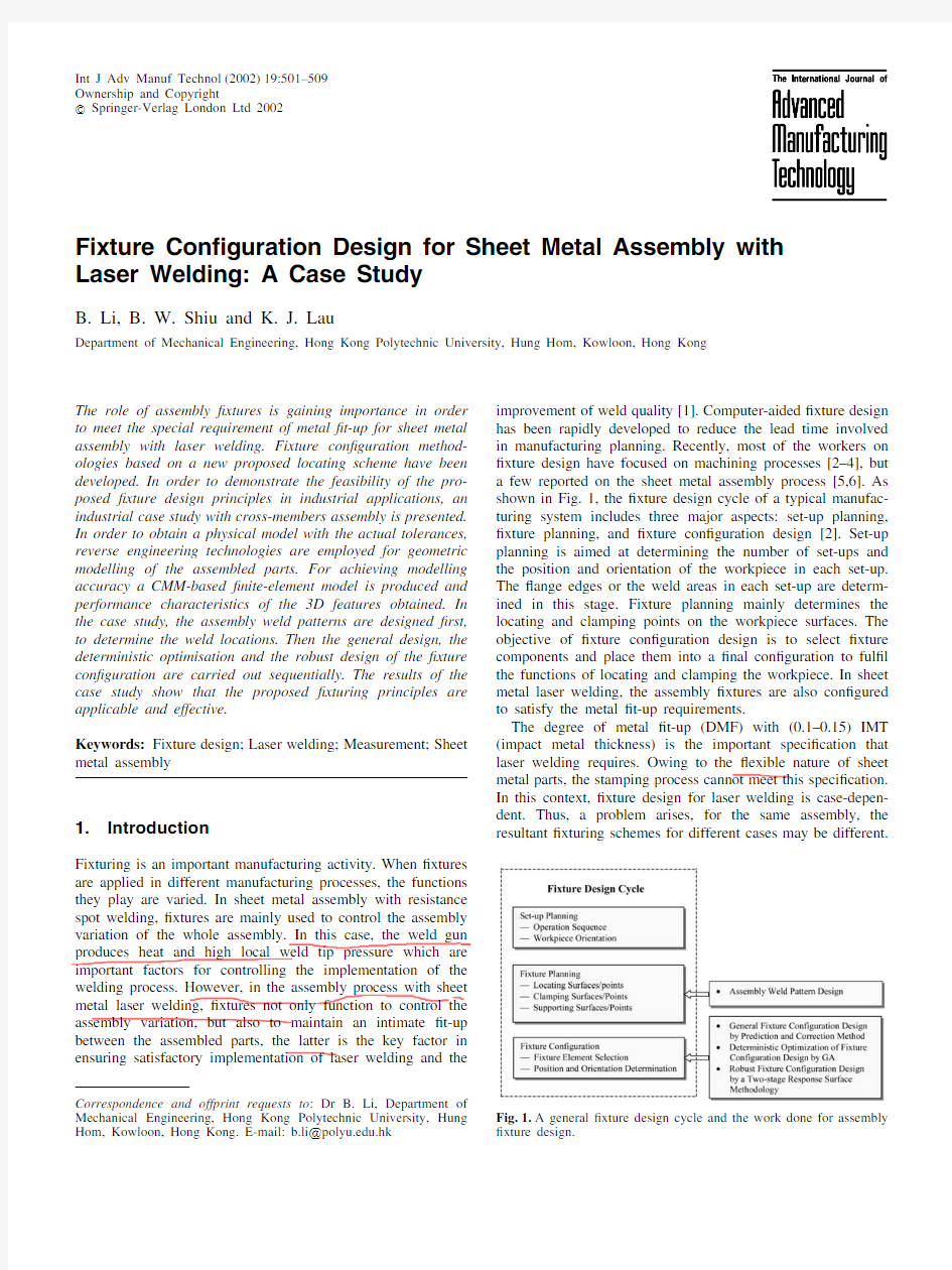
Hom,Kowloon,Hong Kong.E-mail:b.li?https://www.doczj.com/doc/c212467083.html,.hk improvement of weld quality[1].Computer-aided?xture design has been rapidly developed to reduce the lead time involved in manufacturing planning.Recently,most of the workers on ?xture design have focused on machining processes[2–4],but a few reported on the sheet metal assembly process[5,6].As shown in Fig.1,the?xture design cycle of a typical manufac-turing system includes three major aspects:set-up planning,?xture planning,and?xture con?guration design[2].Set-up planning is aimed at determining the number of set-ups and the position and orientation of the workpiece in each set-up. The?ange edges or the weld areas in each set-up are determ-ined in this stage.Fixture planning mainly determines the locating and clamping points on the workpiece surfaces.The objective of?xture con?guration design is to select?xture components and place them into a?nal con?guration to ful?l the functions of locating and clamping the workpiece.In sheet metal laser welding,the assembly?xtures are also con?gured to satisfy the metal?t-up requirements.
The degree of metal?t-up(DMF)with(0.1–0.15)IMT (impact metal thickness)is the important speci?cation that laser welding requires.Owing to the?exible nature of sheet metal parts,the stamping process cannot meet this speci?cation. In this context,?xture design for laser welding is case-depen-dent.Thus,a problem arises,for the same assembly,the resultant?xturing schemes for different cases may be different. Fig.1.A general?xture design cycle and the work done for assembly ?xture design.
502 B.Li et al.
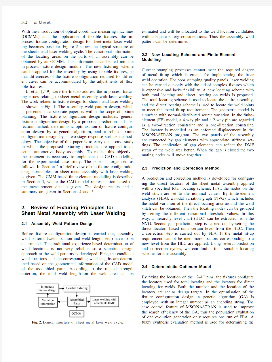
With the introduction of optical coordinate measuring machines (OCMMs)and the application of?exible?xtures,the in-process?xture con?guration design for sheet metal laser weld-ing becomes possible.Figure2shows the logical structure of the sheet metal laser welding cycle.The variational information of the locating areas on the parts of an assembly can be obtained by an OCMM.This information can be fed into the in-process?xture design module.The new?xturing scheme can be applied for the assembly by using?exible?xtures,so that differences of the?xture con?guration required for differ-ent cases can be accommodated by the adjustments of?ex-ible?xtures.
Li et al.[7–9]were the?rst to address the in-process?xtur-ing issues relating to sheet metal assembly with laser welding. The work related to?xture design for sheet metal laser welding is shown in Fig.1.The assembly weld pattern design,which is presented in a separate paper,is within the scope of?xture planning.The?xture con?guration design includes:general ?xture con?guration design by a proposed prediction and cor-rection method,deterministic optimisation of?xture con?gur-ation design by a genetic algorithm,and a robust?xture con?guration design by a two-stage response surface method-ology.The objective of this paper is to carry out a case study in which the proposed?xturing principles are applied to an actual automotive body assembly.To realise this objective, measurement is necessary to implement the CAD modelling for the experimental case study.The paper is organised as follows.In Section2a brief review of the?xture con?guration design principles for sheet metal assembly with laser welding is given.The CMM-based?nite-element modelling is described in Section3,where the CAD model representation based on the measurement data is given.The design results and a summary are given in Sections4and5.
2.Review of Fixturing Principles for
Sheet Metal Assembly with Laser Welding
2.1Assembly Weld Pattern Design
Before?xture con?guration design is carried out,assembly weld patterns(weld location and weld length,etc.)have to be determined.The traditional experience-based determination of weld locations is not very reliable,so a scienti?c design approach to the weld patterns is developed.First,the candidate weld locations and the corresponding weld lengths are determ-ined based on the geometrical information of the CAD model of the assembled parts.According to the related strength
criterion,the total weld length on the weld area can
be
Fig.2.Logical structure of sheet metal laser weld cycle.estimated and will be allocated to the weld location candidates with adequate safety considerations.Thus the assembly weld pattern can be determined.
2.2New Locating Scheme and Finite-Element Modelling
Current stamping processes cannot meet the required degree of metal?t-up which is crucial for implementing the laser weld operation.For poor stamping quality panels,laser welding can be carried out only with the aid of complex?xtures which is expensive and lacks?exibility.A new locating scheme with both total locating and direct locating on welds is proposed. The total locating scheme is used to locate the entire assembly, and the direct locating scheme is used to locate the weld joints to meet the metal?t-up requirement.The geometric model is a surface with normal-distributed source variation.In the?nite-element(FE)model,a4-way pin and a2-way pin are regarded as a two-direction constraint and a one-direction constraint. The locator is modelled as an enforced displacement in the MSC/NASTRAN program.The two panels of the assembly are connected by gap elements with appropriate stiffness set-tings.The application of gap elements can re?ect the DMF status of the weld area better.When the gap is closed the two mating nodes will move together.
2.3Prediction and Correction Method
A prediction and correction method is developed for con?gur-ing the direct locators of the sheet metal assembly applied with a speci?ed total locating scheme.First,the nodes on the weld stitch are set to the nominal values.By?nite-element analysis(FEA),a nodal variation graph(NVG)which includes the nodal variation of the direct locating area around the weld stitch can be obtained.Then the locating nodes can be grouped by setting the different variational threshold values.In this way,a hierarchy level chart(HLC)can be extracted from the NVG.Secondly,a prediction step is carried out by setting the direct locators based on a certain level from the HLC.Then a correction step is carried out by FEA.If the metal?t-up requirement cannot be met,more locators corresponding to a new level from the HLC are https://www.doczj.com/doc/c212467083.html,ing several prediction and correction cycles,we can?nd a?nal suitable locating scheme for the assembly.
2.4Deterministic Optimum Model
By?xing the location of the“2–1”pins,the?xtures con?gure the locators used for total locating and the locators for direct locating for welds.Both the number and the location of the locators are set as design targets.In the optimisation of the ?xture con?guration design,a genetic algorithm(GA)is employed with an integer number as an encoding string.The case control feature of MSC/NASTRAN is used to improve the search ef?ciency of the GA,thus the population evaluation of one evolution generation only requires one run of FEA.A fuzzy synthesis evaluation method is used for determining the
Fixture Con ?guration Design 503
metal ?t-up criterion since the DMF can be within 0.1–0.15IMT.The new DMF criterion is determined by considering a speci ?ed factor set,of weld speed,material type,weld bead width and the degree of penetration into the lower layer panel.Owing to the auxiliary effect of direct locators on total locating,the total locating scheme need not be a “3–2–1”locating scheme,it can be,for example,a “2–2–1”or “1–2–1”,or even a “2–1”locating scheme may be enough.A developed pattern-sorting method is used to determine the number of total locators.The minimised objective function is the maximum DMF of weld joint nodes.Interface programming is used to connect FEA and the GA.
2.5
Robust Design Model
In robust ?xture con ?guration design,the performance charac-teristic of the sheet metal laser welding is the degree of the metal ?t-up along the weld joint.The control variables are the locations of the designed locators.The noise variable in this study is set as the movement of the two-way pin along the x -direction.Response surface methodology (RSM)is employed as a robust design approach to evaluate the interactions between control variables and between control and noise variables.When using RSM,the design variables should change within a relatively small region of interest of the independent variable space [10].A two-stage RSM is developed.The ?rst stage of the methodology is to ?nd the small region of interest which is de ?ned as the robust design space (RDS).In this stage,the design variables are assumed to be independent.In the second stage,a response surface model is set up based on the resulting small region.In order to form a second-order model of the response surfaces,a 3k fractional factorial design (such as a Box –Behnken design)is employed.The response value is the degree of metal ?t-up.The minimised objective function which connects the robustness and the performance with the weighted factors ?1and ?2is used for determining the RDS as shown in Eq.(1).
Minimise F c (x )(1)
??1
?K ?h ?2
?
N T i =1
??f i +1?f i ?1?2?
+?2(f i ??IMT)
where f i ?1,f i ,f i +1refer to the performance function of the node i and its two neighbouring nodes;h represents mesh size;
K
Fig.3.Measuring ?xture scheme for cross-member assembly.is a coef ?cient to balance the magnitude;N T refers to the number of design locators for both the total locating scheme and the direct locating scheme;?is a coef ?cient of quality speci ?cation (the range of ?can be 0.1–0.15).By using robust ?xture con ?guration design,the resulting design scheme is less sensitive to the location uncertainty of the input variables produced by manufacturing and assembly errors.The in ?uential design locators can also be detected by tests on individual regression coef ?cients of the ?tted response model.
3.CMM-Based Finite-Element Modelling
3.1Selection of the Experimental Assembly
There are several potential production applications of sheet metal laser welding in automotive industry,e.g.door inners,motor compartment rails,A -pillars,body sides,bumpers,B -pillars,?oor pans,lift gates and wheelhouses.In North Amer-ica,such other applications as seat reinforcements,cross-beam members,dash panels and seat risers are being examined [11].The selection of the experimental assembly depends mainly on two factors:
1.The parts must be suitable for laser welding.
2.The dimensions of the parts should be relatively small for easily shipping to the laboratory and also for ease of measurement under laboratory conditions.In this study,the cross-members assembly of BIW (body-in-white)is used in the measuring experiment.As shown in Fig.3,the assembly includes two parts,a large part with dimensions of 1200?180?120mm 3and a small part with dimensions of 360?180?80mm
3.The material of the two panels is mild steel with Young ’s modulus E =207000N mm ?2
and
Fig.4.Digitised measurement by CMM.
504 B.Li et al.
Table 1.Design results of weld location (WL)candidates.
Total patch 28Included patch 7Total number 22number on weld number per weld of WL con ?guration area WL Maximum angles (deg.)WL candidates con ?guration number Part 1Part 2Part 1Part 210.0937374 1.548441P120.000000 1.758605P230.765278 1.786967P340.000000 1.707148P450.000000 1.194342P560.0000000.895913P6P670.6691910.641160P7P780.0000000.641160P8P890.0000000.814675P9P9100.0000000.801145P10P10110.9809470.958530P11P11120.9982460.958530P12P1213 1.3001940.998350P13P1314 1.6570470.757643P14P1415 1.4816590.847940P15P1516 1.969000 1.168268P16P1617 2.457149 1.545972P17P1718 2.340084 1.655090P18P1819 2.901358 2.105234P19P1920 2.577895 1.891445P20P2021 1.748533 1.725405P21
P21
22
1.565100
1.338755Boundary angle ?0=1.5°?0=1.0°
21patches 16patches
WL candidates for assembly (weld length =80mm)Patch number P6,P7,P8,P9,P10,P11,P12,P13,P14,P15,P16,
P17,P18,P19,P20,P21
Designed P6,P7,P8,P9,P10,P11,Weld length =35mm two welds P12Weld length =35mm
P15,P16,P17,P18,P19,P20,
P21
Fig.5.NVG for general ?xture design.
Poisson ’s ratio ?=0.3.In this experiment,one selected set of the cross-members assembly of good manufacturing quality is used.
3.2CAD Model Representation Based on Measuring Data
Both weld pattern design and ?xture con ?guration design are carried out based on the ?nite-element model.In order to obtain the ?nite-element model,geometric modelling must be carried out ?rst.The experimental parts in this study are obtained from the automotive workshop,but CAD models of the parts are not available.Even if the CAD models were available,it would still be impossible to apply them directly for ?xture design since we need a model with tolerances,whereas the CAD model is only a nominal model without tolerances.It is thus necessary to create a CAD representation from the actual model.In this context,reverse engineering methodology [12]is employed to solve this problem.Reverse engineering is based on techniques for measuring the shape of physical models and data processing techniques for constructing CAD models from the measured data.Currently,there are many different kinds of digitising technologies available,rang-ing from manual touch-probe devices and coordinate measuring machines (CMMs)to laser scanning systems and industrial CT scanners.Each technology has its own strengths and limitations.As high accuracy is required in this study,a CMM is employed to measure the auto-body parts,and the measuring data will be used for ?nite-element modelling.
In this measuring experiment,a “CONTURA ”CMM with a moving bridge con ?guration is employed,and the correspond-ing supporting software packages are Calypso and Holos.Calypso software is used for probe calibration and the de ?nition of base alignment of the measurement system.Holos software is used for digitisation of the physical surfaces of the parts.The ?rst step in the measurement is the division of the digitised surface.Based on the geometrical features of the digitised surface,the workpiece surface will be divided into more patches.In order to make it easier to probe the boundaries of the surface,the division mesh is marked with a marker pen.Since in this case the weld areas are distributed on the ?ange area of the assembly,the measuring points with high density are set on the ?ange area.The other important factor which must be considered in this step is that the design of the surface division should be convenient for constructing the surface.The second step is the set-up of the measuring ?xtures.The ?xture requirements for measurement purposes are quite different from those for welding.The main role of the measuring ?xtures is to keep the dimension of the parts stable.The ?xturing scheme in this case is not necessarily limited to a “3–2–1”or “4–2–1”locating scheme,additional clamps and supporting poles are required.In industrial applications a popular checking ?xture is often a die base with some clamps applied.However,in the laboratory the use of a die base is not cost-justi ?able,so clamps and supporting poles are employed.The automotive parts are freeform parts;the measuring ?xture elements are used to clamp the sheet metal parts onto the worktable of the CMM.If necessary,a measuring datum is provided for base alignment.Figure 3shows the ?xturing scheme for measure-ment.Clamps A1,A2,%,A6and supporting poles B1,B2,B3,B4are used to locate part 1;locating blocks C1,C2,C3,C4and the supporting poles D1,D2,D3,D4are used to locate part 2.The base alignment is de ?ned on part 1,a 2D
Fixture Con ?guration Design
505
Table 2.HLC for general ?xture design.Level i V i (mm)Number of Nodal ID number
applied locators 10.5435,6,30
20.565,6,30,3,13,15,
30.4295,6,30,3,13,15,9,18,29
40.37115,6,30,3,13,15,9,18,29,1,17
50.36145,6,30,3,13,15,9,18,29,1,17,8,19,28
60.34165,6,30,3,13,15,9,18,29,1,17,8,19,28,12,38
70.30195,6,30,3,13,15,9,18,29,1,17,8,19,28,12,38,10,20,31
80.26225,6,30,3,13,15,9,18,29,1,17,8,19,28,12,38,10,20,31,4,14,36
90.2255,6,30,3,13,15,9,18,29,1,17,8,19,28,12,38,10,20,31,4,14,36,2,25,32100.16285,6,30,3,13,15,9,18,29,1,17,8,19,28,12,38,10,20,31,4,14,36,2,25,32,33,35,40
110.11315,6,30,3,13,15,9,18,29,1,17,8,19,28,12,38,10,20,31,4,14,36,2,25,32,33,35,40,26,27,37
120.08335,6,30,3,13,15,9,18,29,1,17,8,19,28,12,38,10,20,31,4,14,36,2,25,32,33,35,40,26,27,37,7,41
130.06365,6,30,3,13,15,9,18,29,1,17,8,19,28,12,38,10,20,31,4,14,36,2,25,32,33,35,40,26,27,37,7,41,22,23,24
140.04395,6,30,3,13,15,9,18,29,1,17,8,19,28,12,38,10,20,31,4,14,36,2,25,32,33,35,40,26,27,37,7,41,22,23,24,16,21,24
15
41
5,6,30,3,13,15,9,18,29,1,17,8,19,28,12,38,10,20,31,4,14,36,2,25,32,
33,35,40,26,27,37,7,41,22,23,24,16,21,24,11,
39
Fig.6.Finite-element model.(a )Whole model.(b )Local ?ne mesh on weld location.
line connecting the centre-points of the locating hole and locating slot,and a point on the side plane of part 1is also de ?ned.Subsequent to the measuring operation based on the division mesh,the approximation of the surface segments can be obtained.Then by constructing surfaces from the measured patches,the CAD representation of the two parts can be obtained.The digitised measurement by the CMM is shown in Fig.4.
506 B.Li et al.
Table3.Design results of the case study.
“2–1”pins Part1:1257
Node number Part1:1100
Part2:2422Part2:2655
Restrained direction(X,Y)(X)
Total locating scheme Part1:“4–2–1”Part1:“2–1”
Part2:“4–2–1”Part2:“2–1”
DMF(mm)0.1025640.103837
Number of direct locators General?xture design:9Optimal design:7
Designed locators with“2–1”total locating scheme
Robust design
Initial scheme Optimal scheme Mean of RDS Robust scheme
(?1=0.7,?2=0.3)
Part1Part2Part1Part2Part1Part2Part1Part2
21152748286332412848322028473221
21182745293233152119274421192744
21122741364833883017344330163444 Node number21292734310135403052348021272736 21552764306134893156355931553558
21562763301034323061348921522765
21042774296033442970338021002762
DMF(mm)0.091870.085040.12509
0.11806
Fig.7.Optimisation of the number of designed locators.
3.3Finite-Element Modelling
The digitised surface model obtained from the CMM can be imported to the NASTRAN software.The imported surface must be cleaned and some small features which are not important to the FEA must be deleted to improve analysis ef?ciency,then the?nite-element model can be generated. Based on this FE model,the assembly weld pattern design and the?xture con?guration design can be carried out.
In the?xture con?guration design,we are concerned with whether the DMF of the weld can meet the laser welding speci?cation.It is very important that the FE model,in parti-cular,the weld area on the model,can re?ect the real-life manufacturing quality.The best measurement operation is thus one based on the actual assembled location of the two parts. However,in this way,the measuring?xture will be very complicated in order to keep the two?ange edges of the assembly in intimate?t-up,since we do not have any physical information available at this stage.As some manufacturing datum for each part exists,if these datums are set as measuring datums,the measurement?xture will be greatly simpli?ed.So, in this study,we measure the two assembled parts separately. In order to connect the two parts in the MSC/NASTRAN software,three mating points on each part must be recognised. Then,based on the point information,the align and rotate operations in MSC/NASTRAN are carried out.The?nal model for analysis is thus obtained.
In this paper,the mesh density of the FE model along the ?ange edge is5mm.If the length of the?ange edge is L, the number of element edges along the?ange edge is N= L/5.Thus,the weld area of interest can be set as3rows×N+1columns.However,the probe stylus will touch the outer surface of the panel,while the FE modelling is along the mid-plane of the panel.In order to avoid the metal thickness problem involved,we take the measured surface as the required mid-plane.For complicated3D sheet metal shapes,the DMF is calculated in the following way.Assuming the nodal coordi-nates of two mating weld joint nodes from the CMM are(x1, y1,z1)and(x2,y2,z2)and when a certain?xture scheme is set in position,the corresponding deformations after FEA are (?x1,?y1,?z1)and(?x2,?y2,?z2);the DMF is then evaluated by the3D distance between the two mating nodes on the weld area,as shown in Eq.(2).
DMF=?([(x2+?x2)?(x1+?x1)]2+[(y2+?y2)(2)?(y1+?y1)]2+[(z2+?z2)?(z1+?z1])2)
Fixture Con?guration Design507 Table4.Analysis and test of the second-order response model.
Analysis of variance
Source of variance Sum of Squares DOF Mean square F-ratio F0.05,n1,n2 Regression 3.0671×10?4358.763217×10?67.512 1.915
Residual 2.7997×10?524 1.166564×10?6
Lack of?t 2.3857×10?521 1.136030×10?60.8238.655
Pure error 4.1409×10?63 1.380308×10?6
Total 3.347×10?459R-square=0.9087
Mean response0.12457RootMSE:0.00108
Test on individual regression coef?cients
Variable Coef?cient t for H0t0.025,24:
Estimate(coeff.=0) 2.0639
intercept0.12577250232.8956+
X1?0.00049778?2.111473+
X20.000028120.117465?
X3?0.00001075?0.048760?
X40.00092008 4.173289+
X5?0.00089274?3.993961+
X60.00139358 6.320977+
X70.002022919.050120+
X1×X10.000177670.568850?
X2×X2?0.00063972?2.037592?
X3×X3?0.00058420?1.870445?
X4×X4?0.00189833?6.077879+
X5×X5?0.00003184?0.101422?
X6×X60.000161670.517622?
X7×X7?0.00020109?0.640508?
X1×X2?0.0000174?0.045500?
X1×X30.000032130.084126?
X1×X40.000257310.513628?
X1×X50.000250380.655664?
X1×X6?0.00024300?0.636351?
X1×X7?0.00085275?2.233122+
X2×X3?0.00000275?0.007202?
X2×X4?0.00011228?0.245861?
X2×X5?0.00011661?0.263927?
X2×X6?0.00000125?0.003273?
X2×X70.000023420.058870?
X3×X40.00112188 2.937887+
X3×X50.000017880.046810?
X3×X6?0.00001775?0.046482?
X3×X7?0.00094463?2.473717+
X4×X5?0.00014825?0.388227?
X4×X60.000266500.697891?
X4×X70.00046438 1.216073?
X5×X6?0.00026975?0.706402?
X5×X7?0.00027860?0.700844?
X6×X70.000331000.866799?
4.Design Results
The?rst step in?xturing design is weld design.The weld areas in this assembly are the?ange edge of the small part and the corresponding mating area of the long part.The assembled weld design shown in Section2.1is carried out, and the weld location candidates are given in Table1.The loading status of this assembly,when being assembled into the BIW frame,is very complicated.Based on experience, assuming the average shear load applied in this assembly is 1.8kN.The thickness of the panel is1mm and the allowed boundary strength[?e]is30MPa.Thus,the minimum total length of the weld can be obtained,which is60mm.From consideration of the distribution of the original DMF,two welds each of35mm can be determined.The patch number of the two welds is listed in Table1.The second step of this design is?xture con?guration design.General?xture design is carried out based on the“4–2–1”locating scheme for the two assembled parts.The nodal variation graph and the hier-archy level chart for general?xture design is shown in Fig.5 and https://www.doczj.com/doc/c212467083.html,ing the prediction and correction method,9
508 B.Li et
al.
Fig.8.Response surfaces for the main designed locators.
direct locators are required to achieve a DMF of 0.102564mm (the allowed DMF limit is set at 0.13mm).Testing with different total locating schemes,from “4–2–1”to “2–1”,the DMFs are almost unchanged.This is because the weld type of this assembly is a butt weld,so the total locating direction is different from the variational direction of the weld lines,moreover,the part dimension is large.Thus,for an optimal and robust ?xture design,only direct locators are taken as designed locators when the “2–1”total locating scheme is applied.The ?nite-element model of this case study is shown in Fig.6.
The ?xture design results of this case study are presented in Table 3.In the optimisation of ?xture design,the number of locators is treated as a design variable and is optimised ?rst,based on a coarse mesh size;results show 7direct locators are enough to achieve a DMF of 0.09187mm.The optimisation process is shown in Fig.7.The optimal result based on a ?ne mesh with 7locators shows that the DMF in this case can be 0.9187mm.Taking the result of the determi-nation of robust design space as the centre-point a ?1mm variation in the robust design space is determined.The control variables are designed locators (D 1,D 2,%,D 7)and a 3k fractional factorial BBD is carried out.The analysis of variance and the test for independent variables in the response model are shown in Table 4.From the table,we can see the in ?uential terms of the
R(X)=0.1257725?0.00049778X1+0.00092008X4?0.00089274X5
+0.00139358X6+0.00202291X7?0.00085275X1X7(3)
+0.00112188X3X4?0.00094463X3X7?0.00189833X4
2
response model.The approximate response function with in ?u-ential terms is shown in Eq.(3).The optimal results are:X1=?1,X3=?1,X4=1,X5=1,X6=?1and X7=?1.Thus,the locator D2can be set at a location X2=0.The four response surfaces for locators D1and D7,D3and D7,D4and D7,D3and D4are shown in Fig.8.The robust design results are also given in Table 3.
5.Summary
This paper carries out a case study of automotive assembly by applying the ?xture con ?guration design methodologies developed for sheet metal laser welding.A selected cross-member assembly of BIW is taken as the example.In order to obtain a physical model of the car body parts with actual tolerances,a CMM is employed for the measurement of the parts.A CMM-based ?nite-element model is then generated.In this case study,the degree of metal ?t-up is no longer a 1D variation,but a 3D variation.Thus,the distance between the mating nodes in 3D space is regarded as the performance characteristic of this design.
By using the weld pattern design method,two 35mm long welds on the ?ange edges and the weld area and locating area are determined.For general ?xture design,additional direct locators are required.In previous design methods the number of these will be used directly in the optimal design,whereas in this paper,the number of direct locators is treated as a design variable.The optimal process is thus a dynamic design process.First,the number of designed locators is optimised
Fixture Con?guration Design509
on the locating area with a coarse mesh;then,global optimis-ation is carried out using a?ne mesh for the locating area. Robust design is then followed up with the two-stage response surface methodology developed.The in?uential designed locators are detected and a robust?xturing scheme is obtained. The optimal design scheme has better performance character-istics,but the robust design scheme is less sensitive to the location variability.From this case study,we can see that the proposed?xture con?guration methodologies can effectively meet the requirement for industrial application. Acknowledgements
The author is grateful to Dr Jan Shi at the Department of Mechanical Engineering,University of Michigan for providing experimental parts.This work is supported by Hong Kong Polytechnic University Research Fund G-V699.
References
1.D.Avilla,Laser Welding Design and Process Fundamentals and
Troubleshooting Guideline,Ro?n-Sinar,1996.
2.W.Ma,J.Li and Y.Rong,“Development of automated?xture
planning systems”,International Journal of Advanced Manufactur-ing Technology,15,pp.171–181,1999.
3.Y.Rong,X.Liu,J.Zhou and A.Wen,“Computer-aided setup
planning and?xture design”,International Journal of Intelligent Automation and Soft Computing,3(3),pp.191–206,1997.
4.A.J.C.Trappey and C.R.Liu,“A literature survey of?xture
design automation”,International Journal of Advanced Manufactur-ing Technology,5(3),pp.240–255,1990.
5.Mark R.Rearick,S.Jack Hu and S.M.Wu,“Optimal?xture
design for deformable sheet metal workpieces”,Transactions NAMRI/SME,21,pp.407–412,1993.
6.W.Cai,S.J.Hu,J.X.Yuan,“Deformable sheet metal?xturing:
principles,algorithms and simulation”,ASME Journal of Manufac-turing Science and Engineering,118,pp.318–331,1996.
7.B.Li,B.W.Shiu and https://www.doczj.com/doc/c212467083.html,u,“Principle and simulation of
?xture con?guration design for sheet metal assembly with laser welding.Part1:Finite-element modelling and a prediction and correction method”,International Journal of Advanced Manufactur-ing Technology,18(4),pp.266–275,2001.
8.B.Li and B.W.Shiu,“Principle and simulation of?xture
con?guration design for sheet metal assembly with laser welding.
Part2:Optimal con?guration design with genetic algorithm”, International Journal of Advanced Manufacturing Technology, 18(4),pp.276–285,2001.
9.B.Li,B.W.Shiu and https://www.doczj.com/doc/c212467083.html,u,“Fixture con?guration design
for sheet metal laser welding with a two-stage response surface methodology”,ASME Design Engineering Technical Conferences, paper No.DETC2001/DAC-21096,2001.
10.D.C.Montgomery,Response Surface Methodology:Process and
Product Optimization Using Designed Experiments,John Wiley, New York,1995.
11.B.Irving,“Automotive engineers plunge into tomorrow’s joining
problems”,Welding Journal,73(12),pp.47–50,1994.
12.A.Hideki and S.Yuu,“Autonomous measurement of physical
model shape for reverse engineering”,Transaction NAMRI/SME, 27,pp.251–256,1999.
Notation
F c minimised objective with combination of robust-
ness and performance
f i?1,f i,f i+1performance function of the node i and its two
neighbour nodes
h mesh size
K coef?cient to balance the magnitude
N T number of design locators for both the total and
direct locating scheme
?coef?cient of quality speciation
(x1,y1,z1)node coordinates of weld joint on part1
(x2,y2,z2)node coordinates of weld joint on part2
(?x1,?y1,?z1)nodal deformation of weld joint on part1
after FEA
(?x2,?y2,?z2)nodal deformation of weld joint on part2
after FEA
X1,X2,%,X7coded variables of the designed locators
NO: 生产订单号:订单数量:检验日期: 产品名称/型号:规格型号:每箱 PCS,共箱 送检数量:抽样方案:□全检; □抽检MIE-STD-105E-ⅡCR:0 MAJ:0.25 MIN:0.65;□其它; 抽检数量: 检验 项目 检验要求检验结果判定 订单信息核对控制类型□不可控类/□可控,控制器型号;□合格□不合格灯具灯点数/发光颜色灯点数;发光颜色;□合格□不合格电源规格型号/品牌□恒流/□恒压;型号/品牌;□合格□不合格LED灯规格/管芯品牌□SMD/□DIP/□食人鱼; 规格/品牌;□合格□不合格透镜型号/规格;□有□无□珠面/□条纹面/□磨砂面/□光面,发光角度□合格□不合格公母接插头线;□有□无 □2芯/□3芯/□4芯;□圆线/□扁线;□白色/□黑色 □灰色;线长 CM ;□其它; □合格□不合格灌封胶;□有□无□不灌胶/ □灯面灌胶;胶水型号;□合格□不合格灯具标记;□有□无□厂标 / □中性/ □客户LOGO ;□合格□不合格 灯具标识基本内容 □有标识标签 □无标识标签 产品型号/名称:;□合格□不合格 厂商名称或LOGO: ;□合格□不合格 额定值:电压 V, □DC/□AC; 最大功率 W,□合格□不合格 IP防护等级;□合格□不合格 电击防护类型:□0类/ □Ⅰ类/ □Ⅱ类/ □Ⅲ类□合格□不合格 F-Mark: □□□ □合格□不合格 外观检验灯具本体外表 □脏污/□胶渍/□刮花/□掉漆/□脱色/□变形/□裂痕 破损/□灯孔错位/□缝隙/□灯罩色差/□漏螺丝/□螺丝 打花 □线扣/端盖松脱间隙/□安装座松脱锁滑牙 □其它; □合格□不合格灯具内部 □灯珠顶部粘胶/□少胶露底/□多胶/□透镜偏位/□透 镜松脱/□异物/□锡渣/□螺丝打花/□假焊空焊/□掉件 /□器件少装□器件错装/□焊线脱落□焊线反□焊线错 □其它; □合格□不合格线材 □无印字/□印字模糊/□脏污/□刮伤/□破皮/□型号错 □焊反/□焊错/ □其它; □合格□不合格 装配确认底座、支架、连接片与灯 具配装 □松动/□松脱/□对装不到位/□漏螺丝/□螺丝打花 /□少配件/ □其它; □合格□不合格
产品检验报告 产品名称: 型号规格: 检验日期:2016 - - 依据标准: 最终判定:□合格□不合格 编制 审核 批准
章节检验 项目 检测(标准)要求检验结果 单项 判定 1.0 外观外观标识检查 1.1 包 装 外 观 外箱应有清晰,牢固、正确的标志,如注册商标、产品系 列和名称、电源额定电压、频率、厂名、厂址、传真、邮 编、产品编号、规格功率、重量、光色、光源型号、产品 执行标准字样、数量、最大限堆层数、外箱尺寸,生产日 期以及认证标志和向上、轻拿轻放、怕湿、禁止翻转图示 等;材质按样板 符合生产要求 ok 外箱平整、清洁、无刮伤、破损等影响外观的缺陷,标示 字样大小一致,无色差现象,外箱合口不得有大于3mm的 间隙;印刷内容完整,字体清晰 外箱堆放排列整齐,堆码层限不超标且包装可靠。 外包装无明显的损伤ok 1.2 合 格 证 说 明 书 合格证上应标明检验日期和检验员签章,且字迹清晰。 说明书给出产品用途、特点、正确安装接线图、使用和维 护所必须的详细说明、使用注意事项等。 所提供的光电性能参数,额定功率、额定电压、外形尺寸 参数表应清晰无误; 说明书中应有清晰的厂名、厂址、联系电话以及邮编, 且字样大小正确。说明书必须包括第章中标贴上没 有的附加内容 符合设计生产要求 ok 1.3 标贴 外观 标贴上应有清晰牢固的标志,如:制造厂名称或注册商标、 产品型号规格、额定电压、额定频率、额定电流、功率因 数、CCC标志、产品编号、执行标准;具体至少要满足章 之规定,同时所标识内容与证书保持一致符合设计生产要求ok
1.4 产 品 外 观 支架:已喷粉支架表面清洁平整,喷粉层均匀厚实、无流 挂、划伤、气泡、桔皮、针眼、锈迹、色差和杂色、污渍 等影响外观的缺陷;支架焊接紧凑吻合无变形,无虚焊、 脱焊、焊穿等现象,且毛刺<0.1MM。 支架面盖表面无明显不平、变形、刮伤、油污、压痕等不 良现象,且商标标示位置正确;在拆装多次后不会出现变 形及卡住现象。 型号标签、警告标、形象标等标签位置正确,内容 清晰,无破损,皱纹,气泡等不良现象,符合样品要求。 产品排放四角正确,无漏装产品及配件的现象。 喷粉件:附着力≤1级。 与产品质量要求一致 ok 章节检验 项目 检测(标准)要求检验结果单项 判定 2.0 结构 功能 结构功能测试符合 2.1 尺寸 测量 测量支架各部位尺寸,应符合设计图纸、封样要求。符合ok 2.2 试 装装标准光源、灯座、启动器等可替换零件或部件进行对应替换 (密封零件和铆接部件为不可替换部件),不能有松动、难装、 装不到位或错位等不良现象。 装拆光管顺畅,不出现卡死光管或卡不住及接触不良现象。 无不合格现象ok 悬挂装置(如:反射罩)应有足够的安全系数,将等于4 倍灯具重量的均匀恒定载荷以灯具通常的受载方向加在灯具 上,历时1H后,部件应无明显变形或脱落现象. 测试通过 ok 2.3 组装 效果 A、支架内走线附近无可能磨损接线绝缘层的锐边、毛口、毛 刺等类似现象,导线可靠的连接在一起,连接导线接触良好, 整齐美观、走向合理,按技术文件正确配色、且线材符合认证 要求。 符合安全生产做法ok
检验报告 Test Report 产品名称:LED路灯 Nsme of Sample 型号规格:30W Type 委托单位:苏州新纳晶光电有限公司 Applicant 检验类别:委托检验 Test Purpose 上海市质量监督检验技术研究院Shanghai Institute of Quality Inspection and Technical Research 国家灯具质量监督检验中心China National Lighting Fitting Quality Supervision Testing Center(CLTC)
国家灯具质量监督检验中心 检验报告报告编号:W010******** 第1页共8页样品名称LED路灯检验类别委托检验 型号规格等级 30W 合格品 商标/委托单位苏州新纳晶光电有限公司 受检单位苏州新纳晶光电有限公司 标称生产单位苏州新纳晶光电有限公司 委托书编号/委托/日期2015年3月9日 到样日期2015年3月11日抽样地点/ 样本数量1个受检批数量/ 生产日期/批号/编号/ 样品到样状态完好 检验地点上海市徐汇区苍梧路900号 检验依据 GB/T9468—2008灯具分布光度测量的一般要求 IESLM-79-08固态照明产品电气和光度测量方法 检验日期2015年3月16日至2015年3月24日 检验结论 本报告仅提供实测值。详见检验结果汇总页。 (检验报告专用章) 签发日期:2015年3月25日委托单位 通讯资料 地址苏州市苏虹东路388号 邮编215100电话0512-********备注 本报告检验结论是根据检验依据仅对所检项目得出的,不代表未经检验的项目或功能 符合要求。 批准俞安琪审核主检 授权签字人 SQI/KJ-JL/BFG-01
面相中的十大凶相都有这些,你知道吗,看完该注意了 谓的面相‘五官’,指的就是‘耳、眉、眼、鼻、口’等五种人体器官。面相就是一个人所具有的独特气质,而成为形或色表现于面上,给人的一种感受。接下来为大家详细介绍面相算命图解大全。面相可分为三庭看,人的眉以上是上庭,人的眉至鼻头是中庭,人的鼻头以下就为下庭。面部三庭要均匀。即额头、眉眼鼻、嘴与下巴的比例要均匀,整个面部显得大方磊落。若是额形生得略高阔饱满,则代表少年运佳,但额不能太高,过高会克夫,太低则少年运差,当然没法早嫁。在面部五官之后,再细分便是十二宫。这十二个宫位囊括了面部所有的特性和吉凶。第一宫:命宫,又为愿望之宫。麻衣曰:其居两眉间,山根之上,为印堂。第二宫:财帛宫,位于土宿,包括天仓、地库、金甲、井灶。主察财运。第三宫:兄弟宫,又称交友宫。麻衣曰:位居两眉。主交友运。第四宫:田宅宫,田宅宫,位于两眼,及上眼睑。主家业运第五宫:男女宫,又称子女宫。麻衣曰:位于两眼之下,又称为泪堂。看子嗣运。第六宫:奴仆宫,麻衣说它位居地阁,重接水星。看管理运。第七宫:妻妾宫,也可以称为夫妻宫,就在眼尾。第八宫:疾厄宫,一说是山根位,一说是年寿位,建议以鼻梁统看。第九宫:迁移宫,迁移者,位居眉角。古相士,以迁移宫的位置看人阴阳宅状况。第十宫:官禄宫,
官禄者,为居中正,上合离宫。反应人的禄命官运。第十一宫:福德宫,福德者,位居天仓,牵连地阁。看福禄之运。第十二宫:父母宫,便是额头的日月角。主看父母的福祸疾厄。看面相,形体外貌、精神气质、举止情态皆可一视而察,情人、恋人、夫妻、同事、朋友之间、感情总会有变化的、是相互信任、倾慕也可以从面相看出来。额头眉毛之间只有一道纵纹。这种面相在相学中被称为天柱纹。有此面相的人个性都很顽强。是属于做事不达目的绝不会放弃,对利益也是分得很清楚。一般来讲他们是不做对自己无利的事情。这样的人不但严以律己。同时对别人的要求也非常严格。但还有就是是这种面相的人有一个特征,那就好是这道纵纹平时是不会出现。当他的身心俱疲的时候,这道皱纹才会出现。鼻子的上部这些部位若是出现了数条横纹的人。有此面相特征者对事物都会表现出十足的热情。甚至可以说是充满激情。不仅是做事情又积极又主动。待人处事也是持着一颗平常心。此外,如果是说笑时出现这种皱纹的人。一般性格都是较为温和。缺点就是比较好管别人的事情。也常常为此惹祸上身。 1、男人的眉毛中间稀疏杂乱、毛形逆生,是为乱性之相, 情绪十分不稳定,伴有较重的暴力倾向。-2、双眉过低而压眼,是为心性阴沉扭曲而走极端。-3、女子眉过粗浓,不仅一生婚姻难成,且有妨夫。-4、印堂过窄小,难容两指的人,一生运势不顺且多灾厄。-5、女子双颧露骨而突起,对夫运
产品检验报告 产品名称:仿羊皮灯系列、水晶灯系列 型号规格:9018-9、9027-8、6238-6-5等一批 检验日期:2011-5-5 依据标准:GB7000.1-2007 GB7000.201-2008 最终判定:□合格□不合格
啥都得自己去处理~~~~~~~~~~~~~~~~~~~~~~~~~~~~~~~~~~~~~~~~~~~~~~~~~~~~~~~~~~~~~~~~~~~~~~~~~ ~~~~~~~~~~~~~~~~~~~~~~~~~~~~~~~~~~~~~~~~~~~~~~~~~~~~~~~~~~~~~~~~~~~~~~~~~ ~~~~~~~~~~~~~~~~~~~~~~~~~~~~~~~~~~~~~~~~~~~~~~~~~~~~~~~~~~~~~~~~~~~~~~~~~ ~~~~~~~~~~~~~~~~~~~~~~~~~~~~~~~~~~~~~~~~~~~~~~~~~~~~~~~~~~~~~~~~~~~~~~~~~ ~~~~~~~~~~~~~~~~~~~~~~~~~~~~~~~~~~~~~~~~~~~~~~~~~~~~~~~~~~~~~~~~~~~~~~~~~ ~~~~~~~~~~~~~~~~~~~~~~~~~~~~~~~~~~~~~~~~~~~~~~~~~~~~~~~~~~~~~~~~~~~~~~~~~ ~~~~~~~~~~~~~~~~~~~~~~~~~~~~~~~~~~~~~~~~~~~~~~~~~~~~~~~~~~~~~~~~~~~~~~~~~ ~~~~~~~~~~~~~~~~~~~~~~~~~~~~~~~~~~~~~~~~~~~~~~~~~~~~~~~~~~~~~~~~~~~~~~~~~ ~~~~~~~~~~~~~~~~~~~~~~~~~~~~~~~~~~~~~~~~~~~~~~~~~~~~~~~~~~~~~~~~~~~~~~~~~ ~~~~~~~~~~~~~~~~~~~~~~~~~~~~~~~~~~~~~~~~~~~~~~~~~~~~~~~~~~~~~~~~~~~~~~~~~ ~~~~~~~~~~~~~~~~~~~~~~~~~~~~~~~~~~~~~~~~~~~~~~~~~~~~~~~~~~~~~~~~~~~~~~~~~ ~~~~~~~~~~~~~~~~~~~~~~~~~~~~~~~~~~~~~~~~~~~~~~~~~~~~~~~~~~~~~~~~~~~~~~~~~ ~~~~~~~~~~~~~~~~~~~~~~~~~~~~~~~~~~~~~~~~~~~~~~~~~~~~~~~~~~~~~~~~~~~~~~~~~
注意事项 1. 报告无“检验报告专用章”或检验单位公章无效。 2. 复制报告未重新加盖“检验报告专用章”或检验单位公章无效。未经委托单位书面同意,不得复制本报告的任何部分。 3. 报告无主检、审核、批准人签章无效,报告应加盖骑缝章。 4. 报告涂改无效。 5. 若对检验报告持有异议,应与收到报告之日起15日内向检验单位提出,逾期不予以处理。 6. 委托检验仅对来样负责。
报告编号: GB 7000.1-2007 灯具 第1部分 一般要求与试验 GB 7000.201-2008 灯具 第2-1部分:特殊要求 固定式通用灯具 GB 7000.202-2008 灯具 第2-2部分:特殊要求 嵌入式灯具 GB 7000.204-2008 灯具 第2-4部分:特殊要求 可移式通用灯具 GB 17625.1-2003 电磁兼容 限值 谐波电流发射限值(设备每相输入电流≤16A) GB 17743-2007 电气照明和类似设备的无线电骚扰特性的限值和测量方法 标记;结构;爬电距离和电气间隙; 接线端子防触电保护;防尘、防固体异物和防水 内部外部接线绝缘电阻和电气强度耐热、耐火和耐电痕 耐久性试验和热试验谐波电流电源端子骚扰电压低温启动主检:审核:批准:
报告编号: 日期:日期:日期: 交流(AC)直流(DC) 0类I类II类III类 连接固定布线的接线端子与插座配合的插头 不可拆卸软缆软线(X型连接Y型连接Z型连接 电源轨道连接器 器具输入插口螺口或卡口灯头 自镇流灯泡管形荧光灯钨丝灯 其他气体放电 电子镇流器电感镇流器电子变压器电感变压器 启动器触发器 荧光灯灯座螺口灯座卡口灯座其他灯座 螺纹接线端子无螺纹接线端子 自复性非自复性 自复位热断流器人工复位热断流热熔丝
灯具成品出货检验报告集团标准化工作小组 #Q8QGGQT-GX8G08Q8-GNQGJ8-MHHGN#
NO: 生产订单号:订单数量:检验日期: 产品名称/型号:规格型号:每箱 PCS,共箱 送检数量:抽样方案:□全检; □抽检MIE-STD-105E-ⅡCR:0 MAJ: MIN:;□其它; 抽检数量: 检验 项目 检验要求检验结果判定 订单信息核对控制类型 □不可控类/□可控,控制器型 号; □合格□不合 格 灯具灯点数/发光颜色 灯点数;发光颜色; □合格□不合 格 电源规格型号/品牌 □恒流/□恒压;型号/品牌; □合格□不合 格 LED灯规格/管芯品牌 □SMD/□DIP/□食人鱼; 规格/品 牌; □合格□不合 格 透镜型号/规格;□有 □无□珠面/□条纹面/□磨砂面/□光面,发光角度 □合格□不合 格 公母接插头线;□有 □无 □2芯/□3芯/□4芯;□圆线/□扁线;□白色/ □黑色□灰色;线长 CM ;□其 它; □合格□不合 格 灌封胶;□有□无 □不灌胶/ □灯面灌胶;胶水型 号; □合格□不合 格 灯具标记;□有□无 □厂标 / □中性/ □客户 LOGO ; □合格□不合 格 灯具标识基本内容 □有标识标签 □无标识标签 产品型号/名称:; □合格□不合 格 厂商名称或LOGO: ; □合格□不合 格 额定值:电压 V, □DC/□AC; 最大功率 W, □合格□不合 格 IP防护等级; □合格□不合 格 电击防护类型:□0类/ □Ⅰ类/ □Ⅱ类/ □Ⅲ 类 □合格□不合 格 F-Mark: □□□□合格□不合 格 外观检验灯具本体外表 □脏污/□胶渍/□刮花/□掉漆/□脱色/□变形/ □裂痕破损/□灯孔错位/□缝隙/□灯罩色差/□ 漏螺丝/□螺丝打花 □线扣/端盖松脱间隙/□安装座松脱锁滑牙 □其它; □合格□不合 格灯具内部 □灯珠顶部粘胶/□少胶露底/□多胶/□透镜偏位 /□透镜松脱/□异物/□锡渣/□螺丝打花/□假焊 空焊/□掉件/□器件少装□器件错装/□焊线脱落 □焊线反□焊线错 □合格□不合 格
中山市***照明有限公司 编号:FM-NLQ-006-1.0 保存期限:3年 成品检验报告 测试报告编号:NLT 备注:本报告附页配有检验过程参考图片和文字说明 检验依据:1、《LED 成品检验规程》;2、订单要求;3、光电测试报告; 判定方法:在判定中“P ”代表合格,“F ”代表不合格,“N ”代表此项无需检验,在“□”里面打钩. 订单号 抽样方案 GB/T2828-2003 AQL 值 A 类 ?0.15 = 0 - 1 产品型号 RPT-P-LEDCR-G2-9IN-14L-840-FWFC-OCC B 类 ? 1.5 = - 客户名称 CST022- 批量数量 pcs 抽样数量 pcs C 类 ? 4.0 = - 生产阶段 ?正常量产 □首批试产 产品类别 ? 替换件 □ 成品灯具 抽样标准 ? 一般检验水平I □ 一般检验水平Ⅱ □ 一般检验水平Ⅲ 检验项目 检验记录 判定 检验项目 检验记录 判定 包 装 配 件 外箱印刷内容 □ 符合 □ 不符合 结构 磁柱吸力 □ 符合 □ 不符合 □ 无需要 外箱结构尺寸 □ 符合 □ 不符合 安全绳扣 □ 符合 □ 不符合 □ 无需要 外箱内盒标贴 □ 符合 □ 不符合 灯罩/护线套 □ 符合 □ 不符合 ? 无需要 生产批号 □ 符合 □ 不符合 螺丝/铆钉 □ 符合 □ 不符合 说明书 □ 符合 □ 不符合 □ 无需要 组件吻合度 □ 符合 □ 不符合 配件包 □ 符合 □ 不符合 □ 无需要 外观 标识 激光铭牌 □ 激光雕刻 □消银龙贴纸 电 子 端子线/插头 □ 符合 □ 不符合 安规标签 □ 符合 □ 不符合 LED 驱动/开关 □ 符合 □ 不符合 默认档位 1 表面外观 □ 符合 □ 不符合 LED 光源色温 □ 符合 □ 不符合 默认档位 Ⅲ 试验 跌落测试 □ 符合 □ 不符合 ? 无需要 遥控/微波 □ 符合 □ 不符合 □ 无遥控 模拟运输 □ 符合 □ 不符合 ? 无需要 备注:以上检验项目详细记录,请参照后面图文说明,图片若是看不清楚可以放大后查看。 检验项目 实 际 测 试 数 据 编 号(积分球抽检1个灯的数据) 01 02 03 04 05 06 07 08 09 10 11 12 额定电压/测试电压(V ) 120 120 120 120 120 120 120 120 120 120 120 120 0~3档功率标称值(W ) 22 22 22 15 15 15 10 10 10 6 6 6 0~3档功率实测值(W ) 0~3档PF 标称值 ≥0.90 ≥0.90 ≥0.90 ≥0.90 ≥0.90 ≥0.90 ≥0.90 ≥0.90 ≥0.90 ≥0.90 ≥0.90 ≥0.90 0~3档PF 实测值 0~3档光通量标称值(LM ) ≥2100 ≥2100 ≥2100 ≥1680 ≥1680 ≥1680 ≥1260 ≥1260 ≥1260 ≥840 ≥840 ≥840 0~3档光通量实测值(LM ) 0~3档色温标称值(K) 4000 3500 3000 4000 3500 3000 4000 3500 3000 4000 3500 3000 0~3档色温实测值(K) 显色指数标称值(Ra ) ≥80 ≥80 ≥80 ≥80 ≥80 ≥80 ≥80 ≥80 ≥80 ≥80 ≥80 ≥80 显色指数实测值(Ra ) 色容差标称值(SDCM ) ≤ 5 ≤ 5 ≤ 5 ≤ 5 ≤ 5 ≤ 5 ≤ 5 ≤ 5 ≤ 5 ≤ 5 ≤ 5 ≤ 5 色容差实测值(SDCM ) 综 合 检 验 判 定 检验员/日期: 审核/日期: 不 合 格 处 理 方 式 □合格 □不合格 月 日 月 日 总经理批准: 月 日
成品检验报告 测试报告编号:NLT201807001 备注:本报告附页配有检验过程参考图片和文字说明 检验依据:1、《LED 成品检验规程》;2、订单要求;3、光电测试报告; 判定方法:在判定中“P ”代表合格,“F ”代表不合格,“N ”代表此项无需检验,在“□”里面打钩. 订单号 抽样方案 GB/T2828-2003 AQL 值 A 类 ?0.15 = 0 - 1 产品型号 RPT-P-LIVC-G2-4FT-20L-840-FWFC B 类 ? 1.5 = - 客户名称 CST022-821089 批量数量 pcs 抽样数量 pcs C 类 ? 4.0 = - 生产阶段 ?正常量产 □首批试产 产品类别 □ 替换件 ? 成品灯具 抽样标准 ? 一般检验水平I □ 一般检验水平Ⅱ □ 一般检验水平Ⅲ 检验项目 检验记录 判定 检验项目 检验记录 判定 包 装 配 件 外箱印刷内容 □ 符合 □ 不符合 结构 磁柱吸力 □ 符合 □ 不符合 ? 无需要 外箱结构尺寸 □ 符合 □ 不符合 安全绳扣 □ 符合 □ 不符合 □ 无需要 外箱内盒标贴 □ 符合 □ 不符合 灯罩/护线套 □ 符合 □ 不符合 □ 无需要 生产批号 □ 符合 □ 不符合 螺丝/铆钉 □ 符合 □ 不符合 说明书 □ 符合 □ 不符合 □ 无需要 组件吻合度 □ 符合 □ 不符合 配件包 □ 符合 □ 不符合 □ 无需要 外观 标识 激光铭牌 □ 激光雕刻 □消银龙贴纸 电 子 端子线/插头 □ 符合 □ 不符合 安规标签 □ 符合 □ 不符合 LED 驱动/开关 □ 符合 □ 不符合 默认档位 表面外观 □ 符合 □ 不符合 LED 光源色温 □ 符合 □ 不符合 默认档位 试验 跌落测试 □ 符合 □ 不符合 □ 无需要 遥控/微波 □ 符合 □ 不符合 □ 无遥控 模拟运输 □ 符合 □ 不符合 □ 无需要 备注:以上检验项目详细记录,请参照后面图文说明,图片若是看不清楚可以放大后查看。 检验项目 实 际 测 试 数 据 编 号(积分球抽检1个灯的数据) 01 02 03 04 05 06 07 08 09 10 11 12 额定电压/测试电压(V ) 120 120 120 120 120 120 120 120 120 120 120 120 0~3档功率标称值(W ) 40 40 40 30 30 30 15 15 15 10 10 10 0~3档功率实测值(W ) 0~3档PF 标称值 ≥0.90 ≥0.90 ≥0.90 ≥0.90 ≥0.90 ≥0.90 ≥0.90 ≥0.90 ≥0.90 ≥0.90 ≥0.90 ≥0.90 0~3档PF 实测值 0~3档光通量标称值(LM ) ≥4850 ≥4850 ≥4850 ≥3650 ≥3650 ≥3650 ≥1850 ≥1850 ≥1850 ≥1210 ≥1210 ≥1210 0~3档光通量实测值(LM ) 0~3档色温标称值(K) 4000 3500 3000 4000 3500 3000 4000 3500 3000 4000 3500 3000 0~3档色温实测值(K) 显色指数标称值(Ra ) ≥80 ≥80 ≥80 ≥80 ≥80 ≥80 ≥80 ≥80 ≥80 ≥80 ≥80 ≥80 显色指数实测值(Ra ) 色容差标称值(SDCM ) ≤ 5 ≤ 5 ≤ 5 ≤ 5 ≤ 5 ≤ 5 ≤ 5 ≤ 5 ≤ 5 ≤ 5 ≤ 5 ≤ 5 色容差实测值(SDCM ) 综 合 检 验 判 定 检验员/日期: 审核/日期: 不 合 格 处 理 方 式 ?合格 □不合格 07月04日 07月 05 日 总经理批准: 月 日
成品检验规范 文件编号:版本号: 编制:日期: 审核:日期: 批准:日期: 生效日期:受控状态:
文件变更记录
1、目的 规范成品入库及出货检验流程,确保出货产品满足客户的需求,不断的提升品质,提高客户的满意度,模拟客户对产品的验证。 2、适用范围 适用于所有LED 灯具产品入库及出货检验。 3、定义 缺陷级别定义 检验面的定义 A 面:直接看到的区域如:玻璃面,铝基板,LED,透镜面。 B 面:不在直视范围,但暴露在外的面,如:灯具两侧面、散热片、铝型材、外壳,电源等。 C 面:正常使用时看不到的面。须拆卸的面。 缺陷代码定义
4、检验条件 检验光源:普通日光灯灯源500lux. 检验角度:如图一所示,产品与水平视线成30°,并在检验时±15°旋转产品。外观检验距离:未点亮距眼睛30cm±10cm,与眼睛成一条直线,点亮后距离 100cm±10cm. 外观检验时间:10s/每个面。 测试设备:见测试项目内仪器。 5、引用标准 GB/T Ⅱ级按接受质量限(AQL)检索的逐批检验抽样计划。 AQL 允收质量水平:MIN= MAJ= CRI=0(抽样方案主要以抽取数量)。 样本数小于或者等于20PCS 时全检处理。 样本的抽取原则:抽取为上中下抽取力求均匀/每板,随机性。 6、作业内容 成品送检 生产作业完成包装成品,移交待检区,开出【送检单】通知OQC 进行检验。 送检原则:生产按4H 的产量或者4H 内生产完的订单进行送检。 产线送检验时须经过IPQC 在【送检单】签字确认,确认是否完成所有生产工序。 OQC 检验 OQC 抽样按执行。 OQC 核对订单要求、工程技术测试要求、检验规范、检验作业指导、图纸、客户要求进行检验。 检验项目与判定标准按7检验内容执行,检验完毕在【送检单】备注后知会生产入
26种面型算命图解 侧面观察 1、凸面型 上停位居前额,代表十五至三十岁、父母缘分、思想智慧等事。从侧面观看,这种面型的额头是向后倾斜,表示思想敏捷,下巴向后退缩,不是行动迅速。 但一个人思想、行动都迅速,则其人是一个容易冲动的人 2、凹面型 这种面型的人额头与下巴皆凸出,形成中央鼻子部位凹入 这种人思想、行动都慢;但有忍耐力,不会轻易冲动,给人感觉城府很深,不轻易向他人吐露心声。 3、直面型 直面形是前额与下巴皆没有凸出或退缩,这种面型的人思想与行动都不会急躁或太慢,做任何事都会按部就班,从容面对。 4、额凸下巴退缩 额凸代表思想慢,下巴退缩则代表行动快。 这种面相的人思想慢而行动快,其行动往往未经深思熟虑,所以常有错误的抉择。 5、额斜下巴凸
额斜是思想迅速,下巴凸出是行动缓慢,这种人碰到任何问题都会立即得到思想是回应,但不会马上行动,而会慢慢地行动,大部分人都是这种下巴。 正面观察 正面观察面型的方法较侧面多,有西洋骨相学的三分法,中国的五分法、十分法 其实三分法与五分有许多相同之处,三分法是以人类的思想、行动、物欲享受划分种类,而十分法只是把三分发再细致分划为十种。 三分法 1、思想型 思想型的人其特点是上额广阔而高,下巴尖而小,形成一个倒三角形。 这种形格的人身材一般都属细小、腰部狭窄、手一般略长、面色带白、头发幼而密。 「思想型」这正是推动他们走向成功之路的因素;所以很多科学家、研究家在未成功之前常常会给人行为疯狂、不切实际之感觉。 这种形格的人适宜做科学研究、教育、建筑师、设计师或数学家、分析家等工作。 2、运动型
运动型的人特点就是颧骨高耸,鼻形长而鼻梁有节,腮骨显露,前额一般较低而额上有横纹、面色带黑、头发粗而多、身材高大强壮。其性格特点是忍耐力强,有冒险精神,有责任心,敢作敢为,刻苦耐劳。 这种面型的人最适合从事劳动工作,如工程师、冒险家、探险家、军人、警察或运动员等 3、享受型 享受型的人其特点是颐部园肥,前额较窄小,形成一个正三角形或圆形的面。鼻形较小,鼻头园而有肉,头发幼而疏,面色略微带红,手脚较短,脸部特别肥大,肉多骨少。 这种人处事圆滑,交际手腕强。这种人最适合经商 以上三种形质,只是基本形而已。因为每一个人同样会兼有思想型、运动型及享受型的特征,只是多寡而已,但最好是三种形质发展平衡,这样可工作不忘娱乐,娱乐不忘工作。 如果思想型过重的话,这种人每天只是充满幻想,不肯面对现实,容易引发神经衰落及头痛病等病症,如果再加上整个脸型搭配失宜,如眉粗,眼无神,鼻形短,这样的话,实际谋生能力多有问题。 如果运动型过重的话,则其人精力充沛,行事冲动,喜欢用武力解决问题。如果再加上形质配合不佳,如鼻形不端正,额骨凸露或低,眼神流露等,则其人大多从事低下的劳动工作,只能温饱而已,老来
LED隔栅灯 NLED 24W(3×8W 雷士照明 委托送样检验
注意事项 1. 报告无“检验报告专用章”或检验单位公章无效。 2. 复制报告未重新加盖“检验报告专用章”或检验单位公章无效。未经委托单位书面同意,不得复制本报告的任何部分。 3. 报告无主检、审核、批准人签章无效,报告应加盖骑缝章。 4. 报告涂改无效。 5. 若对检验报告持有异议,应与收到报告之日起15日内向检验单位提出,逾期不予以处理。 6. 委托检验仅对来样负责。
报告编号: DQ(13)221212-G GB 7000.1-2007 灯具 第1部分 一般要求与试验 GB 7000.201-2008 灯具 第2-1部分:特殊要求 固定式通用灯具 GB 7000.202-2008 灯具 第2-2部分:特殊要求 嵌入式灯具 GB 7000.204-2008 灯具 第2-4部分:特殊要求 可移式通用灯具 GB 17625.1-2003 电磁兼容 限值 谐波电流发射限值(设备每相输入电流≤16A) GB 17743-2007 电气照明和类似设备的无线电骚扰特性的限值和测量方法 标记;结构;爬电距离和电气间隙; 接线端子防触电保护;防尘、防固体异物和防水 内部外部接线绝缘电阻和电气强度耐热、耐火和耐电痕 耐久性试验和热试验谐波电流电源端子骚扰电压低温启动 (检测报告专用章) 签发日期:2015年6月26日 主检:审核:批准:
报告编号: DQ(13)221212-G 日期:日期:日期: 交流(AC)直流(DC) 0类I类II类III类 连接固定布线的接线端子与插座配合的插头 不可拆卸软缆软线(X型连接Y型连接Z型连接 电源轨道连接器 器具输入插口螺口或卡口灯头 自镇流灯泡管形荧光灯钨丝灯 其他气体放电 电子镇流器电感镇流器电子变压器电感变压器 启动器触发器 荧光灯灯座螺口灯座卡口灯座其他灯座 螺纹接线端子无螺纹接线端子 自复性非自复性 自复位热断流器人工复位热断流热熔丝 ———镇流器线圈: