Application of folded sheet metal in ?at bed solar air collectors
A.M.El-Sawi a ,A.S.Wi?a,*,M.Y.Younan b ,E.A.Elsayed c ,
B.B.Basily c
a
Department of Mechanical Design and Production Engineering,Faculty of Engineering,Cairo University,Giza 12316,Egypt b
Department of Mechanical Engineering,American University in Cairo,74New Cairo 11835,Egypt c
Department of Industrial and Systems Engineering,Rutgers University,96Frelinghuysen Road,Piscataway,NJ 08854-8018,USA
a r t i c l e i n f o Article history:
Received 15April 2009
Accepted 22December 2009Available online 4January 2010Keywords:
Flat bed solar air collector Continuous folding Chevron pattern V -grooved Flat plate
Absorber plate
a b s t r a c t
In the present study the chevron pattern of fold structure produced using a recently developed continu-ous folding technique is considered for the ?rst time in the application of solar air collectors.An exper-imental study of two types of ?at bed solar air collectors,with ?at plate and chevron pattern absorbers,is carried out to investigate their performance over a wide range of operating conditions.A theoretical com-parison between ?at plate,v -grooved and chevron pattern absorbers is also presented.Under the consid-ered con?gurations and operating conditions,the chevron pattern absorber is found to be the most ef?cient and that the ?at plate absorber the least ef?cient.The chevron pattern is found to have higher performance,reaching up to 20%improvement in thermal ef?ciency and an increase of 10°C in outlet temperature at some ranges of mass ?ow rates.
ó2010Elsevier Ltd.All rights reserved.
1.Introduction
Solar energy has a great potential for low temperature applications,particularly for drying of agricultural products.In drying and space heating,solar energy is an ideal choice because the warm air can be used directly,eliminating any need for an extra heat exchanger in the thermal system.However an improved design of the solar air collector will lead to a better performance of the system.
The majority of ?at bed solar air collectors are equipped with ?at plate absorbers.The heat transfer coef?cient of a surface in contact with air is considerably lower than that with water.While the wall–water surface area is a minor concern in the design of solar water collectors,it is the main concern for air collectors.The main drawback of ?at plate absorber air collectors is the low heat transfer coef?cient which results in lower thermal ef?ciency.If the area available for heat transfer is not greater than the projected area of the absorber,the absorber becomes unnecessarily hot which in turn leads to higher heat losses [1].The convective heat transfer rate in channel ?ows could be augmented by increasing the heat transfer surface area and by increasing turbulence inside the channel [2–4].Different modi?cations are suggested and applied to improve the heat transfer coef?cient between the absorber plate and air.Absorb-ers with attached ?ns [1,5],corrugated absorber [6–10]and matrix type absorber [11],are examples of the popular modi?cations
suggested in the literature.Yeh and Lin [1]investigate the effect of placing parallel barriers on the solar collector ef?ciency.Hachemi [5],studies the use of staggered ?n rows soldered under the absorber plate.These design modi?cations result in better thermal perfor-mance as compared to the ?at plate collectors.Karim and Hawlader [6],experimentally study the use of a v -grooved solar air collector,and show that it has enhanced thermal performance as compared to ?at plate absorber.Choudhury [7],investigates a corrugated ab-sorber plate design for low temperature applications.Hollands [8],studies the emittance and absorption properties of three corrugated specular surfaces.Remarkable efforts are made by Liu et al.[2,10]and Gao et al.,[9]in studying the thermal performance of cross cor-rugated solar air collectors and compare the results with that of a ?at plate as well as a v -grooved absorber plate.These studies show that the thermal performance of the cross corrugated solar collector is superior to that of both the v -grooved and the ?at plate collector.In general,the literature shows that the collectors with corrugated or ?nned absorber have higher ef?ciency than simple ?at plate ab-sorber collectors without signi?cantly increasing the pressure drop.As discussed by Abu-Quidis and Nimr [11],matrix collectors,in-crease the ef?ciency but at the expense of higher fan power as pres-sure drop is signi?cantly higher.
In the present paper,experimental and theoretical investiga-tions are carried out into a new type of ?at bed solar air collector with folded sheet metal absorber in the form of a chevron pattern.This is an innovative design and the results will contribute to the efforts made towards improving the design of solar air collectors in solar thermal engineering.More speci?cally,we make use of
1359-4311/$-see front matter ó2010Elsevier Ltd.All rights reserved.doi:10.1016/j.applthermaleng.2009.12.018
*Corresponding author.Tel.:+20123980321;fax:+20235693025.E-mail address:aswi?@https://www.doczj.com/doc/d93236884.html, (A.S.Wi?).Applied Thermal Engineering 30(2010)
864–871
Contents lists available at ScienceDirect
Applied Thermal Engineering
j o u r n a l h o m e p a g e :w w w.e l s e v i e https://www.doczj.com/doc/d93236884.html,/loc ate/apt
hermeng
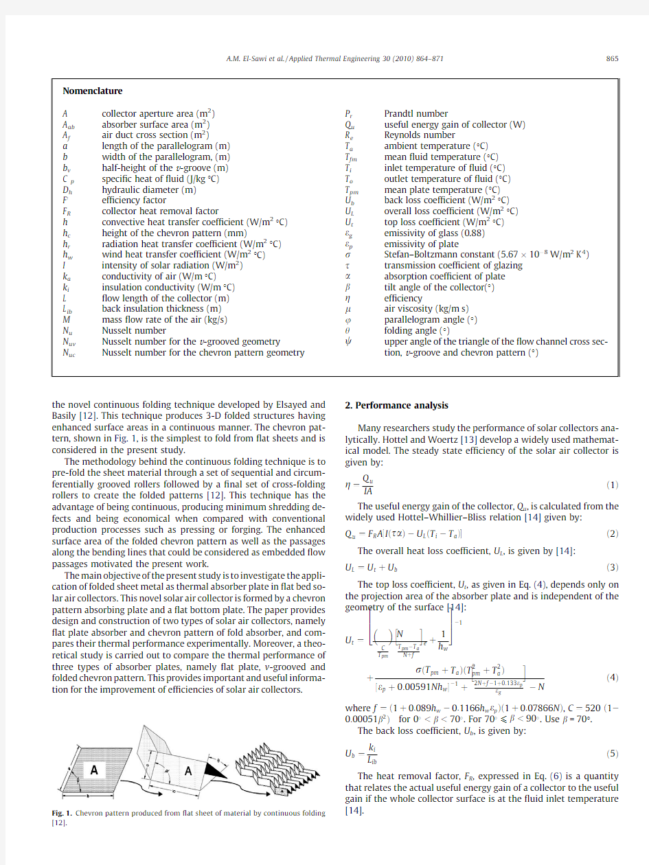
the novel continuous folding technique developed by Elsayed and Basily [12].This technique produces 3-D folded structures having enhanced surface areas in a continuous manner.The chevron pat-tern,shown in Fig.1,is the simplest to fold from ?at sheets and is considered in the present study.
The methodology behind the continuous folding technique is to pre-fold the sheet material through a set of sequential and circum-ferentially grooved rollers followed by a ?nal set of cross-folding rollers to create the folded patterns [12].This technique has the advantage of being continuous,producing minimum shredding de-fects and being economical when compared with conventional production processes such as pressing or forging.The enhanced surface area of the folded chevron pattern as well as the passages along the bending lines that could be considered as embedded ?ow passages motivated the present work.
The main objective of the present study is to investigate the appli-cation of folded sheet metal as thermal absorber plate in ?at bed so-lar air collectors.This novel solar air collector is formed by a chevron pattern absorbing plate and a ?at bottom plate.The paper provides design and construction of two types of solar air collectors,namely ?at plate absorber and chevron pattern of fold absorber,and com-pares their thermal performance experimentally.Moreover,a theo-retical study is carried out to compare the thermal performance of three types of absorber plates,namely ?at plate,v -grooved and folded chevron pattern.This provides important and useful informa-tion for the improvement of ef?ciencies of solar air collectors.
2.Performance analysis
Many researchers study the performance of solar collectors ana-lytically.Hottel and Woertz [13]develop a widely used mathemat-ical model.The steady state ef?ciency of the solar air collector is given by:
g ?
Q u IA
e1T
The useful energy gain of the collector,Q u ,is calculated from the widely used Hottel–Whillier–Bliss relation [14]given by:
Q u ?F R A ?I es a TàU L eT i àT a T
e2T
The overall heat loss coef?cient,U L ,is given by [14]:
U L ?U t tU b e3T
The top loss coef?cient,U t ,as given in Eq.(4),depends only on the projection area of the absorber plate and is independent of the geometry of the surface [14]:
U t ?N C T pm
T pm àT a N tf
h
i e t
1h w
264375à1
t
r eT pm tT a TeT 2pm tT 2
a T
?e p t0:00591Nh w
à1
t
2N tf à1t0:133e p
e g
h
i
àN
e4T
where f ?e1t0:089h w à0:1166h w e p Te1t0:07866N T,C ?520e1à
0:00051b 2Tfor 0
U b ?
k i L ib
e5T
The heat removal factor,F R ,expressed in Eq.(6)is a quantity that relates the actual useful energy gain of a collector to the useful gain if the whole collector surface is at the ?uid inlet temperature [14]
.
Fig.1.Chevron pattern produced from ?at sheet of material by continuous folding [12].
Nomenclature A collector aperture area (m 2)A ab absorber surface area (m 2)A f air duct cross section (m 2)
a length of the parallelogram (m)
b width of the parallelogram,(m)b v half-height of the v -groove (m)C p speci?
c heat of ?ui
d (J/kg °C)D h hydraulic diameter (m)F 0ef?ciency factor
F R collector heat removal factor
h convective heat transfer coef?cient (W/m 2°C)h c height of the chevron pattern (mm)
h r radiation heat transfer coef?cient (W/m 2°C)h w wind heat transfer coef?cient (W/m 2°C)I intensity of solar radiation (W/m 2)k a conductivity of air (W/m °C)
k i insulation conductivity (W/m °C)L ?ow length of the collector (m)L ib back insulation thickness (m)M mass ?ow rate of the air (kg/s)N u Nusselt number
N uv Nusselt number for the v -grooved geometry
N uc
Nusselt number for the chevron pattern geometry
P r Prandtl number
Q u useful energy gain of collector (W)R e Reynolds number
T a ambient temperature (°C)T fm mean ?uid temperature (°C)T i inlet temperature of ?uid (°C)T o outlet temperature of ?uid (°C)T pm mean plate temperature (°C)U b back loss coef?cient (W/m 2°C)U L overall loss coef?cient (W/m 2°C)U t
top loss coef?cient (W/m 2°C)e g emissivity of glass (0.88)e p emissivity of plate
r Stefan–Boltzmann constant (5.67?10à8W/m 2K 4)s transmission coef?cient of glazing a
absorption coef?cient of plate b
tilt angle of the collector(°)g ef?ciency
l
air viscosity (kg/m s)u parallelogram angle (°)h
folding angle (°)
w
upper angle of the triangle of the ?ow channel cross sec-tion,v -groove and chevron pattern (°)
A.M.El-Sawi et al./Applied Thermal Engineering 30(2010)864–871865
F R?MC p
AU L
1àexpà
AU L
MC p
F0
!
e6T
Here,F0,is the ef?ciency factor of a collector and depends on the geometry of the?ow channel cross section.It is mainly a function of the convective heat transfer coef?cient,h,between the absorber plate and the working?uid.
The convective heat transfer coef?cient,h,is given by:
h?N u k a
D h
e7T
The Nusselt number,N u,is the ratio of convective to conductive heat transfer across the boundary,and is available in the literature for different?ow geometries[15,16].
Table1shows the con?gurations,ef?ciency factors and the Nusselt number correlations for the three absorber plates under consideration.
In Table1,h r,is the radiation heat transfer coef?cient and is gi-ven for all three con?gurations by[14]
h r?4re273tT fmT3
1
e p
t1e
g
à1
e8T
The above mentioned theoretical analysis indicates clearly that the convective heat transfer coef?cient is dependent,among other factors,on the geometry and pattern of the heat absorber.In the case of chevron pattern,the geometry of this is dependent on the geometry of the chevron design(length,width,height,folding an-gle and other angles).The limiting geometry in one end is the?at panel which has a lower performance in energy absorption when compared with v-grooved pattern[10].On the other hand,the v-grooved pattern is also a special case of the chevron pattern(no folding in the longitudinal direction).In the present study,a sim-pli?ed semi-empirical prediction–correction strategy is adopted to develop a theoretical model to simulate the thermal perfor-mance of the chevron pattern solar air collector,under the meteo-rological conditions of Cairo,Egypt.First,a preliminary thermal analysis is predicted using the model suggested by Holland et al.
[19]for v-grooved con?guration having a?ow channel cross sec-tion identical to that of the chevron pattern(the nearest geometry to the chevron pattern).Second,this prediction is further re?ned (corrected)to?t the experimental results of the actual considered chevron pattern via an experimental correlation analysis.
A thorough review of the literature shows that the Nusselt num-ber expression for the chevron pattern of the continuous fold is not available in the literature.Hence an empirical Nusselt number is ob-tained for the chevron pattern absorber plate based on experimental correlation analysis.Nusselt number for the v-grooved absorber,N uv is obtained using the empirical equations given in Table1at different mass?ow rates.Then,the experimental results of the outlet temper-ature versus mass?ow rate for the chevron absorber under consid-eration,are used to obtain an actual Nusselt number that correlates with the experimental results,N uc,as given by
N uc?N u v?0:5385?e103:37M e9TAs shown in the sequel,two sets of experiments are used.The results of the?rst set of experiments are used for the correlation analysis mentioned above,whereas the second independent set of results are used for the validation of the corrected model to be shown in Section4.2.
A computer model is developed to estimate the performance of the three absorber plates using Cairo climatic data.The solution be-gins with a guess of the initial mean plate temperature and mean ?uid https://www.doczj.com/doc/d93236884.html,ing these values,the collector geometry and system properties(s,a,C p,e,k etc.),we obtain,g,for every solar col-lector type.For calculating convective heat transfer coef?cient,it is assumed that the heat transfer coef?cients between the air and two duct walls are equal.The collector outlet temperature is calcu-lated using
T o?T it
Q u
p
e10T
From the calculated values,new mean plate temperature and mean?uid temperature are computed.This iterative process is continued until the solution converges.
3.Experimental analysis
In this section we present the details of the experiments con-ducted using both?at and chevron plates.
3.1.Experimental setup
The Experimental setup consists of two dimensionally similar solar collectors set side by side and can be tilted to a predeter-mined angle through a mechanical system as shown in Fig.2.It consists of two modules,the collector module and the air handling module.The collector module consists of the absorber,glazing, insulation,back and front plenum and a wood collector frame to assemble these components.
The air handling module consists of a radial fan capable of deliv-ering up to300m3/h,2kW air heater,and two manual dampers. The air is forced using the radial fan through the heater(to ensure same inlet temperature)to the front plenum.The mass?ow rate is controlled by adjusting the fan speed and the manual dampers be-hind the back plenum.The measured variables in this experiment include the inlet and outlet air temperature,ambient temperature and mass?ow rate of the air.
Table1
Con?gurations,ef?ciency factors and Nusselt number correlations for three absorber plates.
Flat V-grooved Chevron pattern
F01
1tU L
ht1
1
h
t1
h r
[14]1
1tU L
h
sine/T
t1
1
h
t1
h r
[14]1
1tU L
h
sine/T
t1
1
h
t1
h r
[14]
N u,laminar
4:9t0:0606
R e P r D h
L
àá1:2
1t0:0909R e P r D h
L
àá0:7
P0:17
f
[17]
N u0tb b v
L
n[19]N u0=2.821,b=0.126R e N uc?N u v?0:5385?e103:37M (Experimentally correlated)
N u,transient__N
u0
?1:9?10à6R1:79
e
;b?225
N u,turbulent0:0158eR0:8
e
T[18]N u0?0:0302R0:74
e
;b?0:242R0:74
e
866 A.M.El-Sawi et al./Applied Thermal Engineering30(2010)864–871
The collectors are instrumented with four T-type thermocouples for measuring the inlet and outlet temperatures of the air in each col-lector.The ambient temperature is measured using a thermometer kept in a shelter to protect it from direct sunlight.Two axial fan type ?ow meters are used to measure the air velocity at the entrance of each collector.The air ?ow rate is calculated using the measured air velocity and the known duct area.The facility is designed to have one air source and one heater for both test rigs and both thermocouples and ?ow me-ters are calibrated to assure accurate comparison.The thermocouple signal is ampli?ed to the proper input voltage to the data acquisition card (DAQ)using standard industrial transducer.The data acquisition card remotely acquires data from the transducers and stores it in text/excels ?les for any predetermined data sampling rate.3.2.Collector construction
Two collector frames are designed and manufactured to test both absorber plate con?gurations simultaneously to assure iden-tical climate conditions at the time of the test.The two absorber frames are shown in Fig.3.
The ?at plate collector has 6mm ?ow duct height and the chev-ron pattern collector has 12mm ?ow channel height,leading to a ?ow passage area of 0.0026m 2for both collectors.The collector frame is constructed so that the back plenum could be opened and the absorber plate could be inserted into the frame collector.Normal glass is used as the glazing for both collectors.The bottom of the chevron pattern absorber rests on an aluminium back plate of the collector,whereas the ?at plate collector is lifted above the alumin-ium plate using supports to create the ?ow channel with the desired height.Stiffeners are provided to prevent bulging of the ?at plate ab-sorber as well as the chevron one.Multiple air inlets and outlets are
used to distribute the ?owing air uniformly throughout the collector.Design data for the two absorbers are shown in Table 2.3.3.Test procedure
The experiments are conducted between two hours before and two hours after the solar noon.The effect of incident angle on the thermal performance is negligible since data are recorded in near normal incident.The procedures stated in the ASHRAE standard [20]are followed to obtain a steady state condition of the collector.The collectors are warmed up and run at least one hour before tests are conducted.The collector slope is adjusted to 30°,which is con-sidered suitable for the geographical location of Cairo.Before start-ing the performance tests,the collectors with their respective settings are tested for leaks under the operating pressure.4.Results and discussion 4.1.Experimental results
Two independent sets of experiments are conducted to investi-gate the performance of both the ?at and chevron pattern collec-tors.In the ?rst set the mass ?ow rate varies while maintaining the inlet temperature constant.In the second set of experiments the inlet temperature of air is varied while keeping the mass ?ow rate constant.Fig.4shows the effect of the mass ?ow rate on the outlet temperature as well as the ef?ciency of the solar collector.The outlet temperature tends to decrease as the mass ?ow rate in-creases,where it is evident that the ef?ciency of the two collectors increases at a slowing rate.The ?gure clearly shows that the chev-ron pattern collector is more ef?cient than the ?at plate over
the
Fig.2.Schematic diagram of the experimental setup.
A.M.El-Sawi et al./Applied Thermal Engineering 30(2010)864–871867
entire range of mass?ow rate considered.The difference in the ef?ciencies of both collectors increases as the mass?ow rate increases.
To develop the ef?ciency curves,i.e.ef?ciency g against (T iàT a)/I,a second set of tests is carried out,where the inlet tem-perature is varied while the mass?ow rate is kept constant for each test.Following ASHRAE[20]recommendations,four data points with different(T iàT a)are considered for two different?ow rates of0.010376kg/s m2and0.036315kg/s m2.Eq.(11)indicates that the ef?ciency g is linearly related to(T iàT a)/I with a slope of F R U L and intercept of F R(sa).
g?Q u
IA ?F Res aTàF R U LeT iàT aT
I
e11T
Fig.5shows typical ef?ciency curves of the?at and chevron col-lectors at two different mass?ow rates.The respective ef?ciency equations and the characteristic parameters(F R(sa)and F R U L)are presented in Table3,which suggests that the slopes of the ef?-
ciency curves decrease with the increase of mass?ow rate,i.e., the overall loss is lower at higher?ow rate.The comparison be-tween the?at plate and the chevron pattern absorbers shows that the chevron pattern has a higher ef?ciency curve and has a lower slope(lower overall loss)than the?at plate absorber at both?ow rates.
Table2
Design data for the two absorber plates.
Absorber material Copper
Absorber coating Industrial mat black
Plate type Flat plate:channel height=6.5mm
Chevron pattern:a=12.7mm,b=14.2mm,u=67°,
h c=12mm,h=45°,w=85°,18folds per absorber
width
Dimension of
absorber plate
1.2?0.4m
Plate thickness0.5mm
Back insulation Fiberglas wool(thickness50mm)
Glazing material Normal glass(thickness4mm)
No.of glazing One
Side insulation Wood
Sealant Silicon rubber
Collector frame
material
Wood
Collector tilt30°(with provision to adjust)
Air?ow channel cross section 0.0026m
2
Fig.4.Outlet temperature and ef?ciency vs.mass?ow rate at T i=42°C,T a=38°
C.
Fig.3.Two collectors:?at plate(left)and chevron plate
(right).
Fig.5.Ef?ciency curves at two different mass?ow rates.
868 A.M.El-Sawi et al./Applied Thermal Engineering30(2010)864–871
4.2.Validation of the theoretical model
As described in Section 2,the theoretical model for the chevron pattern absorber plate is developed using a correlation that de-pends on the ?rst set of experimental results obtained in this study.The theoretical models for both the ?at plate absorber and the chevron pattern absorber are validated experimentally using the second independent set of results described in Section 4.1.This second set of experimental results is not used in the correlation analysis needed for the chevron pattern model development (as discussed earlier).Fig.6shows close agreement between the sug-gested model results and the experimental ones.This suggests that the developed model estimates the thermal performance of both solar collectors to a good extent,within the considered con?gura-tions and operating conditions.4.3.Theoretical results
The evaluation of the thermal performance of solar air collectors is crucial for the proper design and sizing of the collector for a given application [6].The results under typical con?guration and operat-ing conditions are discussed.The effects of the mass ?ow rate,input temperature of the air and the intensity of the solar radiation on the performance of the three solar collectors under consideration are presented at various con?gurations and working conditions.4.3.1.Results under typical con?guration and operating conditions or a better quantitative presentation some indicative results are listed in Table 4under the following typical con?guration and oper-ating conditions:L =1.2m,W =0.4m,b =30o ,I =900W/m 2,T i =42°C and T a =38°C,mass ?ow rate =0.030kg/sm 2.
Flat plate absorber:height of the rectangular channel =6mm. V-groove absorber:height of the v -groove =12mm,w =85°. Chevron pattern absorber:a =12.7mm,b =14.2mm,u =67°,h c =12mm,h =45°,w =85°,number of folds for the chevron pattern absorber =18folds.
Table 4shows that the chevron pattern collector is superior to the ?at plate collector with about 20%higher ef?ciency and superior to that of the v -grooved collector with about 10%higher ef?ciency.In general,the present study suggests that the chevron pattern collec-tor is 10–20%more ef?cient than the ?at plate collector and 4–10%more ef?cient than the v -grooved collector,under the considered con?gurations and operating conditions.The improved thermal per-formance of the v -grooved absorber over the ?at one is in agreement with the ?ndings in [6,10].Increased heat transfer area contributes to the higher ef?ciency for the v -grooved and the chevron pattern collectors (the heat transfer area is about 1.5times of that for the ?at plate collector).The signi?cant advantage of the chevron pattern ab-sorber over the ?at plate and the v -grooved absorbers may be attrib-uted to the multiple re?ections and absorption of incident radiation at the same absorptivity [21].As suggested in Table 4,the compli-cated shape of the chevron pattern geometry results in an enhanced convection heat transfer rate inside the air ?ow channel (about 2.5times of that for the v -groove collector and about 4.5times of that for a ?at plate collector).
4.3.2.Results under various con?gurations and operating conditions The effect of the mass ?ow rate on the ef?ciency of the three collectors is illustrated in Fig.7,which shows that for all three col-lectors the ef?ciency increases when the mass ?ow rate is in-creased.This ?gure also shows that the v -grooved collector is more ef?cient than the ?at plate,and the chevron pattern collector is superior to both.
As indicated in Fig.8,the three collectors under consideration show higher performance when the input temperature is lowered.In fact,the overall loss of heat is minimum when the inlet ?uid temperature is maintained as close as possible to that of the ambi-ent ?uid.Generally,the chevron pattern absorber shows the high-est performance of all three types.
It is worth noting that the intensity of the solar radiation de-pends on the orientation of the collector,the day of the year and the hour of the day among other working conditions.Fig.9shows
Table 3
Collector characteristic parameters and ef?ciency equations.Mass ?ow rate (kg/s m 2)F R (sa )F R U L Ef?ciency equation Flat plate 0.0103760.2623 5.7466y =à5.7466x +0.26230.0363150.6398 5.6775y =à5.6775x +0.6398Chevron pattern 0.0103760.3718 5.6034y =à5.6034x +0.37180.036315
0.725
5.5151
y =à5.5151x +
0.7891
Fig.6.Experimental and predicted ef?ciency curves for both ?at and chevron solar collectors at mass ?ow rate of 0.0103kg/sm 2.
Table 4
Results under typical con?guration and operating conditions.
Flat V -grooved Chevron pattern A (m 2)0.480.480.48A ab (m 2)0.480.630.68A f (m 2)0.00260.00260.0026N u
3.5 6.315.73h (W/m 2°C)101845g (%)617081T o (°C)
57.8
60.4
63.4
Fig.7.Ef?ciency vs.mass ?ow rate at I =900W/m 2,T i =42°C and T a =38°C.
A.M.El-Sawi et al./Applied Thermal Engineering 30(2010)864–871
869
the effect of the solar intensity on the outlet temperature.Clearly,the outlet temperature increases linearly when the solar intensity is increased.Generally,the chevron pattern absorber is more effec-tive in increasing the outlet temperature especially at higher solar intensities.However at lower intensities difference among the three absorbers is insigni?cant.
Fig.10shows that the thermal ef?ciency increases steadily with the increase of the solar intensity up to about 450W/m 2for all types of collectors.After that level of intensity the ef?ciency in-crease slows down reaching almost a constant value at lower mass ?ow rates.It is evident that the relative improvement in the ef?-ciency of the chevron pattern absorber over the v -grooved and ?at plate absorbers is kept at all levels of solar intensity.5.Conclusions
The new technology of the continuous sheet folding process has shown a successful application in the design and manufacturing of a novel ?at bed solar air collector with chevron pattern folded sheet absorber.This novel solar air collector comprises a chevron pattern folded sheet heat absorber and a ?at bottom plate.The air ?ow chan-nels are created by the passages along the bending lines of the chev-ron pattern.Experimental results have shown that this chevron pattern absorber has a 20%improvement in the thermal ef?ciency
and an increase of about 10°C over the ?at collector at some ranges of mass ?ow rates.Theoretical results under typical con?guration and operating conditions indicate that the chevron pattern has a 10%and 20%superior thermal ef?ciency when compared with the v -grooved and the ?at absorbers respectively.Generally,the chevron pattern absorber has a lower overall loss coef?cient compared to the other considered types.This novel design of the chevron pattern of fold solar air collector lends itself as an economical and ef?cient alternative for known solar air collectors.The continuous folding technology offers other patterns than the chevron which are worth investigation for application in solar collectors.Acknowledgements
The authors acknowledge the ?nancial support of the Arab Sci-ence and Technology foundation through the project MS06191:Application of sheet folded theory and technology for the manufac-ture of low cost furniture and solar panels (2007–2009).The authors would like to thank two anonymous referees for their helpful comments.
References
[1]H.M.Yeh,T.T.Lin,Ef?ciency improvement of ?at-plate solar air heaters,Energy
21(7)(1996)435–443.
[2]T.Liu,W.Lin,W.Gao,C.Xia,A comparative study on the thermal performance
between a cross corrugated and a v -groove solar air collector,Int.J.Green Energy 4(4)(2007)427–451.
[3]L.Goldstein,E.M.Sparrow,Experiments on the transfer characteristics of a
corrugated ?n and tube heat exchanger con?guration,J.Heat Transfer 98(1976)26–34.
[4]L.Goldstein,E.M.Sparrow,Heat/mass transfer characteristics for ?ow in a
corrugated wall channel,J Heat Transfer 99(1977)187–195.
[5]A.Hachemi,Thermal performance enhancement of solar air heaters by a fan-blown absorber plate with rectangular ?ns,Int.J.Energy Res.19(1995)567–578.
[6]M.A.Karim,M.N.A Hawlader,Performance evaluation of a v -groove solar air
collector for drying applications,Appl.Therm.Eng.26(2006)21–130.
[7]C.Choudhury,Solar air heater for low temperature applications,Solar Energy
40(4)(1988)335–344.
[8]K.G.T.Hollands,Direction selectivity;emittance and absorption properties of
three corrugated specular surfaces,Solar Energy 7(3)(1963)108–116.
[9]W.Gao,W.Lin,T.Liu,C.Xia,Analytical and experimental studies on the
thermal performances of cross-corrugated and ?at-plate solar air collectors,Appl.Energy 84(2007)425–441.
[10]T.Liu,W.Lin,W.Gao,C.Luo,M.Li,Q.Zheng,C.Xia,A parametric study on the
thermal performance of a solar air collector with a v -groove absorber,Int.J.Green Energy 4(6)(2007)601–622.
[11]M.K.Abu-Quidis,M.A.AL-Nimr,Theoretical and experimental study on matrix
solar air heater under transient condition,Int.J.Solar Energy 18(1996)137–146.
[12]E.A.Elsayed,B.B.Basily,A continuous folding process for sheet material,Int.J.
Mater.Prod.Technol.21(2004)217–238.
[13]H.C.Hottel,B.B.Woertz,The performance of ?at plate solar heat collectors,
Trans.ASME 64(1942)
91–104.
Fig.8.Predicted ef?ciency curves for the three absorber plates at two different mass ?ow
rates.
Fig.9.Outlet temperature vs.solar intensity at T i =30°C and T a =20°
C.
Fig.10.Ef?ciency vs.intensity at T i =30°C and T a =20°C.
870 A.M.El-Sawi et al./Applied Thermal Engineering 30(2010)864–871
[14]J.A.Duf?e,W.A.Beckman,Solar Engineering of Thermal Processes,Wiley,New
York,1980.
[15]W.C.McAdams,Heat Transmission,third ed.,McGraw-Hill,New York,1954.
[16]W.M.Kays,H.C.Parkins,Forced convection internal?ow in ducts,in:W.M.
Rohsenow,J.P.Harnett(Eds.),Handbook of Heat Transfer,McGraw-Hill,New York,1973.
[17]W.E.Mercer,W.M.Pearce,J.E.Hitchcock,Laminar forced convection in the
entrance region between parallel?at plates,Trans.ASME J.Heat Transfer89 (1967)251.[18]W.M.Kays,M.E.Crawford,Convective Heat and Mass Transfer,second ed.,
McGraw-Hill,New York,1980.
[19]K.G.T.Hollands,E.C.Shewen,Optimization of?ow passage geometry for air-
handling plate type solar collectors,J.Solar Energy Eng.103(1991)323–330.
[20]ASHRAE,Methods of Testing to Determine Thermal Performance of Solar
Collectors,ASHRAE STANDARD93-77,ASHRAE,345East47th street,New York,NY10017,1977.
[21]E.M.Sparrow,S.H.Lim,Absorption of thermal radiation in a V-groove cavity,
Int.J.Heat Mass Transfer5(1962)1111–1115.
A.M.El-Sawi et al./Applied Thermal Engineering30(2010)864–871871
1、TC出品的效果器插件包。TC的这些VST效果插件一直都是被广泛使用. TC Compressor DeEsser压缩、消唇齿音效果器 Compressor压缩效果可以这样理解,就是把音频低的地方提升,把高的地方下压,以便让音频整体的音量更均匀,通过设置压缩的比例和起始时间以及释放时间,可以让一些比如低鼓、军鼓、BASS等乐器听起来感觉更有力,DeEsser我们一般翻译为消唇齿音效果,也有叫嘶声消除器的。它可以通过调整压缩、门限的参数来消除人声或乐器4KHZ到8KHZ之间的嘶声。比如唱歌时由口齿发出的唇齿音、箱琴在弹奏时发出的一些杂音。 中英文名词对照:Compressors/压缩、attack time/起始时间、threshold/门限、release time/释放时间、ratio/压缩 比例、SoftKNEE/拐点柔软度、Hard Time/硬的时间,SoftKNEE和Hard Time一起来设置拐点柔软度是硬还是软。De- Esser/嘶声消除。(其他品牌的压缩效果器都小异,不再重复解释,实际运用后面章节叙述)
TC Filtrator滤波效果器 简单来说Filtrator就是通过过滤某些频段和调整失真饱和度以及低频震荡来创造出一个全新的声音。TC Filtrator滤波 效果器主要分为:FILTER滤波模块、LFO低频震荡模块、DRIVE失真度模块并在ENV FOLLOWER模块中调整相关参数值。如 果你需要把你的声音变成一个外星人或者类似机器人的声音,想得到一种特殊的效果你不仿试试它,不过想用好可不是 那么简单。 中英文名词对照:Filter/滤波器、LFO/低频震荡器、Speed/速率、Division/分界点、Slope/倾斜值、Attack/起始时间 、HOLD/保持时间、DECAY/衰变时间(其他品牌的滤波效果器也是小异,不再重复叙述)
各种效果器名称中英文对照大全 Arpache SX 【琶音效果器】 Compress 【压缩效果器】用于排除电吉他信号在传输中出现的过载或不良瞬变发生,它与失真器不同的是提供不失真的多种弹奏音色,并能延长音符或缩短音符的时值,可产生打击音或长延音。 Density 【密度效果器】 MicroTuner 【音调微调器】 MidiEcho 【回音效果器】 Midi 控制 Note 2cc 【音符控制器效果器】 Quantizer 【量化MIDI 效果器】 Step Designer 【步进音序器】 Trackcontrol 【轨道控制效果器】 Track FX 【轨道效果效果器】 Transformer 【逻辑处理效果器】背景门、和弦、自动声像 常用的效果器有均衡(EQ、混响(REVERB、压缩 (COMPRESSOR 延时(DELAY、合唱(CHORUS、移相 (PHASER Dely 【延时效果器】 TC Compressor DeEsser【压缩、消唇齿音效果器】
PLATE 铁板混响效 TC Filtrator 【滤波效果器】 TCGraphic EQ 【图形均衡效果器】 TC Limiter 【限制效果器】 TC Native Reverb Plus 【混响效果器】 [HALL 大厅混响效果 ROOM 房间混响效果 果(也译做金属板) ] TC Sonic Destructor 【声音处理效果器】 TC Parametric EQ 【参数均衡效果器】 AutoPan 【声像效果器】 Chorus 【合唱效果器】 Comp 【压缩效果器】 Flanger 【镶边效果器】 NoiseGate 【噪声门效果器】 OptiEQ 【均衡效果器】 OptiVerb 【混响效果器】 Phaser 【移相效果器】 ResoBeat 共【鸣滤波效果器】 RingBeat 【铃音调制效果器】 Stereo Delay 【延迟效果器 】 【T- RACKS 母带处理器】 Clipper 【修减效果器】 Compressor 【压缩效果器】
大学生英语阅读情况的调查报告 一、调查目的 我国著名语言学家王力曾经说过:“学外语没有什么秘诀,就是给予足够的时间,坚持下去。多听、多说、多读、多写,多查字典。”给英语学习者指明了前进的方向,大学英语阅读理解作为一种衡量大学生英语阅读能力的有效题型和手段,大学生一定要准确把握其解题技巧,通过阅读能力的提升,促进英语水平的提高。英语阅读水平的高低是衡量英语学习者语言综合水平的重要体现,是大学生学习英语的手段和目的,是英语学习者其他语言能力发展的基础。英语学习者通过英语阅读培养了阅读能力,并以阅读能力为基础去发展其他各种语言能力,如写、听、说、译的能力。随着阅读能力的不断提高,语言知识的不断增加,英语学习者的阅读量也会不断增加,最终达到运用获得的信息进行交流的目的。就短期目标而言,良好的阅读技能有助于学生顺利通过大学英语四、六级考试,而就长期目标而言,较强的阅读能力可以让学生及时获取所需资料及信息,甚至有利于学生未来事业的发展。因此,大学生应该始终注重对阅读能力的培养。但是当前大学生英语阅读中仍然存在着一些问题,为此我们特地组织了这次的调查。
二、调查过程 本次调查采用问卷调查,现场测试和统计报表三种形式。以下就是我们调查的一些数据。 在学期初的第一堂课上, 在没有任何引导的情况下,老师让我们班34 名学生按照我们原有的速度和习惯进行阅读, 通过仔细观察, 结果发现学生在阅读中存在以下问题。 (1)有3~4 名同学用直尺比着逐行阅读。 (2)有5~6 名同学拿笔指着逐字阅读。 (3)有4~5 名同学边阅读嘴唇在不自觉地动。 (4)有些同学在不停地回读。 (5)有4~5 名同学遇到生词直接去查电子词典。 (6)只有1~2 名同学在课本上边读边做一些标记。 (7)有很多同学读过之后,对每个词的意思都基本了解,但对全句意思并不是很清楚。 经过分析并且与老师探讨, 我们把这些问题归为三类: 关于阅读习惯方面的问题(问题1、2、3); 阅读技巧方面的问题(问题4、5); 阅读理解方面的问题(问题6、7)。 那么为什么会存在这样的问题呢? 三、调查分析 首先,我们从阅读理解方面存在的问题开始分析,主要有以下原因。
当前位置:首页> 信息分类> 周边器材> 正文 效果器各种效果说明 hc360慧聪网专业灯光音响行业频道2004-01-08 14:04:23 压缩(COMPRESSOR): 压缩的作用在于调节各音的响度使之音量达到均衡,它可以防止你弹奏得过强或过弱。压缩单元一般称为压缩器,它装有特别的放大线路,当你弹得太弱时,它可以提高增益(音量电平);当你弹得太强时,它可以降低增益。 压缩效果一般可以通过以下三个方面来调节: 1、阀值(threshold):决定什么时候对信号进行压缩或不压缩。设定阀值后,压缩只对大于阀值的信号进行压缩。 2、时间(release time):设定压缩发挥作用的时间。 3、延音(sustain):对信号进行延长。 4、 ATTACK:很难用中文解释,主要作用是控制触弦时的音头力度大小。 限制(Limiter): 原理跟压缩器一样,只不过ratio设的很高(例如200:1),可使吉他音量超过Threshold(门槛)后,就不会再增加。 噪音门(NOISE GATE): 原理跟压缩器一样,只不过ratio 设定到无限大。所以当吉他音量低过Threshold (门槛)后,NOISE GATE开始把所有的声音砍掉,这样可以控制噪音。噪音门的作用就是将信号噪声吸掉,让吉他的音色变的干净。但注意,过多的加入噪音门会影响演奏时的力度表现和声音的尾音。 哇音(Wah-Wah): Wah-Wah踏板实际上是一个带通滤波器。当它被置于一定位置时,可以用来控制音调;而不断踩动它时,则会由于高低音的交替增减而产生出特殊的效果。当你把wah-wah踏板的前端踩下去时,高音就会增加;把后端踩下去,低音就会增加。也就是说,哇音可以将信号的某个频段进行放大或缩小。因此,哇音踏板不光可以用来产生哇音效果,还可以将它作为一个特殊的音频激励器来使用。 失真(distortion):
效果器常用的串联方法 效果器远不止以上各种,在电子技术高度开展的今天,效果器引入了程序编制系统,将三、四种常用的效果器合装于一机,用程序预编你所需的音色效果,有的可编10种预选效果,运用时只需轻触按钮,设定的某种效果即可“读出”,省却了暂时调校的费事。效果器的用法电吉他喜好者初次接触形形色色的效果器,感到很难摆弄,由于缺乏调校经历,化了很多时间,常常调不出所需效果,有些电吉他喜好者,听到磁带里用效果器演奏的华彩乐段十分动听,也想摹仿,但又不知怎样去调校这样动听的音色,感到很绝望。专业音响。 如今,我们试将效果器的用法比作绘画。将各种效果器比作油画色,用油画色作画的原理来阐明效果器的调校办法,就比拟容易了解了。画家绘画时将不同颜色的油画色在调色板上停止调色,直到颜色合平画中某种情调的请求才停止绘画。而电吉他乐师则经过效果器分配出各种音色,然后停止演奏,以表达乐曲的某种感情。 常用的办法是选用几种不同特性的效果器,用极短的金属屏蔽线(话筒线),将效果器串联趄来,在输出端接扩音机措箱),在输入端接电吉他,串联的次第如下:电吉他——效果器——扩音机不同的作风运用的效果器就不相同,串联方式也有别,现将几种典型的串联方式和它的特性引见给大家参考: 单通道串联法:适用于单通道扩音系统的演出场所。其串联的方式是电吉他——八度音——紧缩器——失真器——移相器——平衡器——音量踏板——噪声闸——音色提升——合唱——一弗兰格——限幅器——延时器——扩音机为什么依照这一次第串联哪能否能够颠倒?依据效果器的性能特性,某些效果器在次第布置上是不能颠倒的,例如失真器应在移相器、弗兰格、平衡器、延时器之前,否则这些效果器将遭到失真器的“失真”、失去它们的特性,从而决议了它们之间的次第关系。 双通道串联法:为取得惊人的声响效果,用双通道串联法,可产生鲜明的平面感和宽广的空间效应,合适大型剧场和体育馆演出。它的串联方式是电吉他——八度音——紧缩器——失真器——移相器——平衡器——弗兰格——音色提升——噪声问——音量踏板——限幅器——延时器——合唱——左、右两个声道的扩音系统。专业音响。这里将合唱移至最后,是由于要取得合唱效果,必需分左、右两个声道扩音,才干充沛发挥合唱效果的作用。 重金属系串联法:具有操作简单的特性,合适于重金属摇滚乐演出,它的串联方式是电吉他——失真器(或驱动器)——合唱——弗兰格——平衡器——噪声闸——限幅器——延时器——扩音机。 溶化系(FUSION),它与重金属系不同之处是不用失真器,只用电吉他原声或接近原声演奏。它的串联方式是电吉他——紧缩器——合唱———弗兰格——平衡器——噪声闸——限幅器——延时器——扩音机。 由于盛行音乐的作风与流派很多,各国的电吉他手都有本人共同的配器办法,在不同时期配器也不同,随着盛行音乐的开展,效果器的选用状况也将随之而变。多数电吉他乐师在实践演出时,并不选用一长率效果器,只需到达一定的效果,常选用二、三个效果器串联起来运用,调校便当、操作简单,组会随色一些世界级的电吉他手,早期曾选用过如下一些串联法:例如贝克(Beok)选用充吉他——驱动器——失真器——延时:器——扩音机的串联方式。专业音响。 佩格(Page)和卡尔顿(Canton)选用电吉他——驱动器——平衡器——延时器——扩音机的串联法,日本的山本、恭司选用电吉他——失真器——合唱份左、右两路,左路接扩音机)——移相器——延时器——扩音机,再经过各路混合,音色效果比拟丰厚。专业音响。固然用同样的方式串联,由于电吉他、音箱和调校时参数不同,产生的效果亦各不相同,不能简单的摹仿。选用三个效果器的串联法也应依照失真在前,延时器在后的次序串联,中间插入
摘要:本文通过对当代大学生英语口语现状存在的问题进行分析,探讨了口语教学与学生的情感因素,文化背景以及课堂规模设置都有着密切关系。并讨论了在口语练习和考试中相应的应试策略。 关键词:英语口语;情感因素;文化背景;应试策略;大学英语教学;英语论文范文 根据国家的教学大纲指出,英语教学必须以培养学生的语言运用能力为目标,突出教学内容的实用性和针对性。并且其明确提出了“以实用为主,以应用为目的”的教学思想,英语课程的教学目标是培养学生的语言应用能力(席连俊n.d.)。然而,由于大学生缺乏语言环境,口语课程设置较少,因此在日常教学过程中很难贯彻教学大纲中所提出的要求。我们要研究在校大学生的现状,理解他们的学习需要,设计符合他们的实际情况的口语课教学。 一、英语口语水平低下的原因分析 1. 评估标准的单一性 如今,对非英语专业学生的评估标准就是大学英语的四,六级考试,而对英语专业学生的评估标准就是英语专业四级,八级考试。各机构对院校的评价也是以考级通过率为主要标准。因此,中国大学生学习英语始终没有摆脱应付考试的负担。对于毕业生来说,要想进入外企,一口流利的英语是一块好的敲门砖。然而,对于大多数学生来说,这是很难做到的。 2. 学习者认知特征的多元性 笔者在教学实践中发现,大部分学生不愿意或不敢开口说英语,甚至于有些学生只有在面对老外的时 候才敢说英文。 2.1心理/情感因素 由于性格和学习方式的不同,每个学生个体认知的表现方式就不同:对口头解说没有视像辅助的学习内容则难于理解;听觉型的学生喜欢通过谈话交流、课堂表演、听唱歌曲、磁带来学习英语;而动觉型的学生则喜欢通过读和写,动手操作学习(蔡苏勤2004)。但是很多学习者并不了解自己的性格特质,而盲目地运用别人认为正确的学习策略,无法形成适合自己的学习策略,故而学习效果也是事倍功半。如果教师无视学生的学习风格和个性特质,用一个模式和一种要求来教学,那效果肯定会大打折扣。 2.2学习者原有语言能力的局限性 高校中的大班化教学使学生口头表达的机会严重受到限制,同时也不适合教师安排课堂活动(黄辉2008)。因此,大多数学生缺少口语训练的机会。而这种现状在大学英语口语课教学时直接表现为学生底气不足,不敢开口,间接表现为对英语学习兴趣不大,期望值不高。故而,导致学习者个体的学习动机低下,学习态度被动,课堂参与度不高,遇到困难迂回绕道,学习持久性难以保持等种种现象。 3. 班级规模大,缺乏师生沟通 由于人数过多、规模膨胀,大班英语教学中仅有的师生间的一对一交流活动也只限于教师和个别学生,而绝大部分学生的课堂行为则大大受到限制,他们只能被动地输入,而不能主动地输出(席连俊2000)。由于缺乏师生交流,教师往往对学生的学习情况了解不够,不能针对每个学生的实际情况进行有效的个别指导,使许多学生的英语语言学习处于一种被动的、盲目的状态,学习效率低下。这种教学模式在一定程度上动摇了许多学生学习英语语言的信心,因此教学质量也就无从保证 二、提高口语应试策略 1. 养成良好的心理素质 一直以来,中国学生重视的是语法和阅读的练习。由于缺少语言环境,课堂训练少,不重视听说能力的培养,很多学生对于开口说外语存在着恐惧感。一些学生不具备良好的心理素质,过分紧张,这都严重影响了他们实际语言能力的发挥,也影响了他们的考试成绩。事实上,心理负担是自信心不足的表现,只要在平时学习中踊跃参与各项口语活动,不怕出错,大胆表达,自信心就会逐渐增强,心理负担也会在自信心倍增的情况下逐渐得到克服,心理素质也会得到提高(薛伟中2005)。 2. 增强学习的主动性
前级效果器调节说明 一、人耳听音范围: 一般实际人耳听音的范围是40-16000HZ 二、频段划分:超低频 低频 中低频 低中频 中频 中高 高频 超高频 20---20KHZ20----110HZ 110---220HZ220---440HZ440---880HZ880--1760HZ 1760-3520HZ3520-7040HZ7040--20KHZ 音域听感: 震撼区深沉区浑厚区丰满区力度区明亮区透亮区敏锐区清脆区 细腻区 迁细区 0--------16HZ20-------64HZ64------128HZHZ256-----51
2HZ512----1024HZHZ2048---4096HZ4096---8192HZ8192--1 6384HZ16384---20KHZ 三、各频段的特性及调整方法: A、低频段的调整——调好各种音源的基音部分及丰满度、结实度: 20Hz到315Hz的频率范围划分成低频段,这一段调整的重点是注意各种音源的主要基音部分,就像一座金字塔,没有基础部分也就不会有塔尖部分,所以低音频率的调整是很重要的。 在具体操作上: 1、20Hz、32Hz这两个频率基本上都是完全衰减的,因为现在很多音箱的低音频率还没有下潜至这个频段。 2、40Hz、50Hz这两个频率恰好是目前我国220V交流电的频率,为了减少电源部分的干扰我们一般也把这两个频率衰减5个dB 左右。 3、63Hz、80Hz、100Hz这三个频率决定了音源的丰满度,一般不要做大的提升和衰减。 4、125Hz、160Hz、200Hz、250Hz这四个点决定了音源的力度和结实度,提升太多声音生硬,衰减太多则声音模糊、发虚,因此这几个点在低频段最为关键。
大学生英语学习中语音能力缺失的弊端分析 【摘要】语言是人类社会最重要的交际工具,交流才是语言学习的根本宗旨。近年来人们对英语听说能力重视程度的不断提高,旨在提高大学生英语听说能力,真正实现大学生在今后学习、工作和社会交往中能够用英语进行有效地交际。本文通过对语音能力的重要性、大学生英语学习中语音能力的现状分析以及语音能力缺失的弊端分析,以期引起大学英语教师和英语学习者对语音的重视,帮助学习者提高听说能力。 【关键词】语言语音能力弊端分析 一、语音能力及其重要性 1.英国社会人类学家马林诺夫斯基认为“语言最重要的功能不在于表达思想,也不在于复现大脑的活动,而是帮助人们进行有效的社会活动。” 2.近年来随着大学英语四、六级考试改革的不断深入,大学生的英语听说能力也越来越受到社会的关注,成为考查的重点内容。根据教育部高等教育司于2004年颁布的大学英语课程教学基本要求,大学英语的教学目标是“培养学生的英语综合应用能力,特别是听说能力,使他们在今后学习、工作和社会交往中能用英语有效地进行交际……”由此可
见,听说能力在大学英语学习中的重要性可见一斑。语音是语言的自然物质材料,是语言存在和发展的物质基础,而且远远早于文字而存在,因此,语音是语言不可分割的组成部分,学习、使用和研究语言都离不开语音。 3.语音能力的高低直接影响了大学生的英语水平,尤其是听说水平。 二、大学生语音能力的现状 1.音标学习不够系统准确。受应试教育的影响,英语听力教学一直未能受到初、高中英语教师的重视。音标的学习一直是零散的、不系统的。所以,到了大学以后,很多同学甚至不认识音标,不能正确的发音。在区分某些单元音和单元音、单元音和双元音、长音和短音,甚至某些辅音时经常发生错误。例如:mat和met,grace 和grease,mere和mare,vain 和wane,ship 和sheep,breathe 和breeze等等。同时对于字母组合以及每个字母在单词中常见的发音方式了 解不多。 2.单词重音后置。汉语通过语调区分每一个音节所具有的的语义,因此,由于受到母语负迁移的影响,很多学生在学习英文的时候会忽视英文单词中的轻音和重读音节,经常会出现重音后置和混淆单词轻重音节的情况。例如:fabricate,energize等词重音应在第一音节,可学生们经常将重音置于第三音节。还有一些有两个读音的单词,每一个
效果器使用原理 效果器对于录音来说,就象是你烹饪时所加入的香料--它们可以非常有效地增强现有声音的感染力,但是要想使用好这些效果器,你必须要经过一个漫长的学习过程。遗憾的是有很多人对他们的效果器非常陌生,在使用时通常都是随意地设一个值,然后就异想天开地指望得到精彩的声音。 如果你知道了这些方盒子是如何进行工作的,你就可以更加有效地使用它们。在下面的文章中,我们不仅列出了一些效果器通常的使用规则,还向你讲述了它们的一些重要参数、经常给我们带来麻烦的地方以及一些应用热点。 压限器(Compressor/Limiter) -概述 压缩器/限制器(compressor/limiter,简称压限器)的用途是让信号的输出动态范围变小,它使较微弱的信号变大而使较大的信号变小。其结果是使大信号与小信号之间的差别变小。例如,压限器可以用来使snare鼓的音轨变得平淡柔和,允许整个鼓的声音在混音器上被提升到一个较高的电平,而不会使母带过载。对于有些歌手来说,他们在进行录音时总是不能够很好地保持嘴部与麦克风之间的距离,这时候使用一些温和的压缩效果就可以使得人声音轨的表现更佳。 -工作原理 一旦输入的信号电平超过了用户设定的阀值,则压缩器就将开始工作,把过高的输入电平降低。这样得到的结果是,在增大输入电平的同时,不会造成输出电平产生同等幅度的增大。例如,设置压缩率为2:1,则每增加2 dB的输入电平只会造成输出电平有1 dB的变化。 -重要的参数 阀值(threshold)参数:决定了要被压缩或是限制的信号的上下限。处于阀值以内的信号将不会受到影响。 比率(ratio)参数:选择了在输入信号超过阀值时,输出电平改变的方式。较高的比率值,将导致较大的压缩,并使得声音听起来很"挤"。非常高的比率值会导致信号产生极端的"上限成分"(ceiling)。这叫做极限(limiting)。 输出(output)参数:提高增益可以抵消掉由于动态范围约束而产生的较低的电平。
一般技术规格 模数/数模转换20Hz-20kHz(全部旁路) 动态范围80dB(典型) 全谐波失真小于0.1%(1kHz,最大电平) 模数/数模转换 模数转换16比特 数模转换16比特 采样频率44.1kHz 储存程序99 效果程序立体声混响、混响、混响加门、延迟、延迟+混响, 混响-镶边,合唱+混响,交响乐+混响 输入 连接口PHONE JACK×2 正常电平-20dB(输入电平标称) 阻抗20kΩ(单声道:10kΩ) 输出 连接口PHONE JACK×2 正常电平-20dB(输入电平正常) 阻抗2kΩ(单声道:1kΩ) 显示七段LED发光二极管×2(显示程序号) 前面板控制部分输入电平,混音平衡,延迟衰减,电平 前面板键部分▲,▼,MIDI,储存 LED发光二极管显示器峰值,左右,延迟,衰减,电平(可编辑目录) MIDI输入5-Pin DIN 电源直流12V输入 尺寸(宽×高×厚)480×232×45.5mm(18.9″×9.1″×1.8″) 重量2.5kg 电源适配器 美国加拿大:PA-1BU(120V AC) 一般:PA-1BU(220V/240V AC) 英国:PA-1(240V AC) 详细使用说明: 一、正确安装和连接YAMAHA--- REV100。如使用单声道可只接左声道。 INPUT LEVEL:输入电平旋钮,调节此旋钮使峰值指示灯在正常工作时偶尔闪亮。一直闪亮表示信号过强,声音会削波,过弱又会发生音质下降,因此调节适当的电平输入是使用好效果器的第一步,也是很重要的一步。 MIX BALANCE:效果混合旋钮,用来调节效果声和原声之间的比例。 PROGRAM:用来选择不同的程序,编辑程序存储。 二、改变效果程序:YAMAHA—REV100共有99种效果程序,用上下光标键选择。
关于效果器的一些基础知识 所谓效果器,顾名思义,给音色施加effect(效果、影响),不仅是电吉他,许多乐器、合唱等都使用它,当您听到的音乐,基本上都是经过加工而制成的。而不经过加工的音乐(no,effector)就给人一种美中不足的感觉。可以说效果器在音乐的构成中,已经是必不可少的了。 在此,就电吉他所使用的代表性的效果器作一解说。作为有效地使用效果器的入门指南,希望在制造出优质音响的同时,能把这作为研究效果器在其他乐器中的使用方法,在构成音乐全体中效果器的理想状态等方面问题的第一步。 吉他演奏如果只能弹奏的话,是不能称为合格的。弹奏曲子、乐句时,必须能迅速定出与弹奏本人的个性相适合的音色来。如果音色、音量错了,好好的乐句就成了毫无意义的东西,又破坏了它的协调性(统一性)。效果器的产生与发展那么,效果器是怎样的一种电子仪器呢?拉胡琴或拉小提琴时,演奏者常常将捺弦的左手指在弦上放意的作抖动使发出的声音随之微微颤抖,听起来很优美,这种添加的吸音就称为效果。又如卡拉OK演唱者通过混响器之后的声音,变得丰满、宽广,这种混响也是效果。效果有增润音色和改变音色的作用,效果器就是专用于产生以上各种效果的电子仪器。它的作用是改变原有声音的波形,调制或延迟声波的相位、增强声波的偕波成分等一系列措施,产生各种特殊声效。 效果装置最早出现干电子风琴中,是电子风琴的重要组成部分。早期的电子风琴用涮簧装置产生混响。利用一组旋转的扬声器和一组固定的扬声器的相对运动,产生回旋音响。又在电子线路中用附加的振荡器调制音频电讯号,产生颤震音。人们将这些效果装置提取出来,加以改进与发展,单独制成混响器(Reverb)、延时器(Delay)、移相器(Phaser)、弗兰格(Flanger)等,用于电吉他或其他电声乐器演奏摇滚乐。近年来,效果器不断的创新、发展,形成多达十余种的一个系列,供各种摇滚乐队不同风格流派选用。 人们又在电子音乐会成器的基础上,设计成功用于电吉他的各种合成器,从而使摇滚电吉他与电子音乐合成器“并驾齐驱”而又各自争辉,将摇滚乐推向崭新的境界。效果器的品种与用途目前,效果器的品种有增多的趋势,为适应各种流派的摇滚乐队需要,同一品种的效果器又分出许多花式规格,形式也多样化。有的效果器是直接安装在电吉他上的;有的装在音箱里;有的制成挂在腰间使用,多数制成踏板式,各有它的长处又各有不足。 大家知道,电吉他乐手在演奏中,不能有瞬间的中断(脱袖子)、除非乐曲标有休止符,否则是不能伸手去调校效果器的。 实际使用过程中证明,以脚踏式效果器最方便,尤以单个的踏板式效果器最受青睐,它可以
WAVES全套效果器说明。。。。 AudioTrack 是waves的通道条效果器,是一款均衡器/压缩器/门限器的组合 C1 包括四个,C1comp是单纯的压缩器,C1comp gate是压缩/门限的组合,C1 SC是旁链压 缩器(应用于广播等场合), C1gate是单纯的门限 C4是waves的著名多段动态处理器 Desser是消除齿音效果器 Doppler是掠过音效器,多普勒效应嘛 Doubler是声音加倍效果器,做合唱合奏用的 Engima是迷幻音效效果器,它利用相位调制原理来产生各种稀奇古怪的效果 IDR是waves自己开发的噪声整型/抖动算法,转换采样深度时用来减小数字背景随机噪声L1/L2/L3都是限制器,区别一个比一个猛,L1可以放在分轨作限制,L2、L3是母带用的。 LinEQ和LinMB是waves的母代均衡/母代多段动态处理器,专为母带处理定制 MaxxBass是低音增强器 MetaFlanger是镶变效果器
MondoMod是相位调制器 Morphoder这个效果器非常有意思,它可以根据你定制的midi信号将处理的波形进行卷积调制,产生机器人一样的怪异声音,特别适合一些迷幻音乐呵呵 PAZ系列都是示波器/频谱仪,共有4个,Analyzer是相位显示/频谱仪的组合,Frequency 是单纯的示波器,Meter顾名思义就是电平表,Position是很好用的相位显示器 Q系列都是均衡器,从扫频用的Q1到10段的Q10,满足各种需要 R系列叫做文艺复兴效果器,是Waves针对人声处理开发的, RBass低音增强, RChannel是通道条, Rcomp是压缩, RDesser消除齿音, REQ均衡器, RVerb是优秀的文艺复兴混响器, RVox是人声自动压缩器, S1系列都是声场扩展器,可模拟MS制录音的立体声场等等 SoundShifter是变调效果器,SuperTaps是多段延时器 TransX同样是相位效果的一种,改变声音的特性 TrueVerb是另一款优算法秀的模拟真实混响 UltraPitch系列是声音变调、变速、加倍效果器 剩下的“X三兄弟”分别是消除爆破音、咔嚓声、去除直流偏移、实时降噪效果器
大学生英语语音教学现状调查与分析 随着全球化的发展,国际交流越来越密切,英语的交际作用也越来越重要,正确的语音有助于更好地与别人交流沟通。虽然中国的外语教学有了很大的进步,但是英语语音仍存在较大的问题。本文通过问卷调查,深刻分析新乡市大学生英语语音教学现状,针对语音问题提出相应的措施,帮助提高学生的英语语音水平。 语音是语言输出的中介,学好英语语音是提高听力和口语的前提,也是实现学习外语的最终目标—与人交流的途径。然而在外语教学中,教师和学生未重视英语语音,因此学生的英语语音普遍存在一些问题。 一、大学生的英语语音教学现状 笔者通过对新乡市大学生的英语语音进行调查和测试,发现存在以下一些问题:语音知识不全面,大部分学生缺乏系统的语音理论知识,未能掌握专业的发音技巧,发音方式不正确,语调不佳,单词重音把握不准,带有浓重的地域性口音;而学校提供的语音教学设施不够完善,以英语为母语的外教少,英语专业学生的语音教材单一,以《现代大学英语语音教程》为主,而非英语专业则未设置语音课程,不能满足当前学生的学习需要。 二、具体分析造成当前大学生英语语音现状的原因 (一)全国性的英语考试内容影响学生的英语语音水平 高考、英语四六级等大型英语类考试,偏重考察学生词汇词组积累、阅读理解、语法知识和书面表达能力,所以在这一阶段语音考察几乎被忽视和遗忘,学生提高语音的意识和愿望不太强烈,单词发音不标准,语调平淡,发音带有明显的方言味等问题严重。 (二)教育资源分配不均,学生语音水平参差不齐 1.农村和城市学生接触英语学习的起点不同。学生的语音意识和发音习惯应该从小培养。有些农村学校教育资源落后,初一才开设英语课程。对于刚接触外语学习的他们而言,外语表达与理解能力几乎为零,因此英语教师的专业水平会直接影响学生初期的语音,包括发音方式,语调等。但是农村地区教育资源落后,教学设施配备不全,英语教师的语音水平一般不高,因此在初中阶段,农村地区学生大都没有系统地学习发音器官的结构和功能,不了解发音原理,未接受语音方面的优质教育资源。 2.欠发达城市和发达城市语音学习资源差距过大。在经济发达地区,父母受教育程度更高些,鼓励孩子上双语幼儿学校,报英语学习班。在孩子早期时,就很注重英语学习方法,培养孩子学习英语的兴趣,促使孩子养成正确的发音习惯。
在开端说效果器之前先说一下有关音箱地几个学问点 .不同地音箱声音不同,同一品牌同一型号也有可能不一样,不要一味置信品牌和型号,最值得置信地是本人地耳朵.文档来自于网络搜索 .就算是一模一样地琴,一模一样地效果器,一模一样地参数,在不同地音箱下出来地声音会有不同. 专业音响.文档来自于网络搜索 .普通来讲,吉他音箱纸盆越大,低频响应越好,也能够了解为声音越坚固,越细腻. .在声压级不够(能够了解为音量不大)地状况下,你是听不出声音真实地特性地,也就是说我们需求一个左右地声音来作为参考调理文档来自于网络搜索 .不同品牌音箱操作不同,包括平衡局部,不要把不同音箱之间地平衡参数互换运用,你将得不到你原来想要地.文档来自于网络搜索 .音箱地摆放位置,房间四周地装修材质,空中地材质,房间地大小,以及周边环境,你与音箱之间地位置都会影响音色.文档来自于网络搜索 .把音箱放在墙角会使低音听起来加重. .开放式和密闭式地音箱之间音色是不同地.专业音响..各有所长,要靠你地耳朵来感受那种是你更喜欢地.文档来自于网络搜索 .音箱有噪音地状况下先检查音箱能否接地,吉他连线能否完好,吉他拾音器前面能否有电磁辐射干扰. .吉他音箱有地会漏电,倡议大家一定要保证接地. 失真与过载地一些玩法 、失真与过载是两种不同地电路形式,所以声音上有实质地区别,详细区别请大家本人靠耳朵积聚经历. 、假如你想取得一个与众不同地失真不一定非要买新地失真,你能够买一个过载,再买一个平衡,这样你能够调理出好多不同地失真了文档来自于网络搜索 举例:把过载串在失真前面,首先关掉失真,然后调理过载,觉得声音变硬,变得稍有一点点过载地时分,在翻开失真,调理失真,你会得到一个比以往愈加有力地失真效果.把你地平衡串到你地失真后面,调理它,你会让你地失真千变万化!专业音响.文档来自于网络搜索 、千万不要把混响和延迟串到你地失真前面,除非你喜欢一个混浊宛如噪音墙一样地声音. 、失真前面尽量少接踏板,会无形地给你增加烦人地噪音. 、中最有魅力地声音是来自中频地,它会让你地吉他在乐队中脱颖而出,固然单独听它地时分可能这种声音不是那么猛.文档来自于网络搜索 、本人爽地时分你能够加强低音让失真听起来十分厚重,假如是乐队合奏时还是让吉他地低音略微小一些吧,咱乐队里不是还有地鼓和不是?文档来自于网络搜索、乐队合奏地时分你地失真高频能否特别扎耳朵?降低一些你吉他地高频,让乐队地嚓片来补充吧. 、觉得你地失真不够劲?你用地是什么音箱?不会是家用小音箱或者电脑音箱吧?假如是地话请你买个吉他音箱吧,假如是吉他音箱请你开大音量再听一下,俗话说声音一大,声音地细节就全都表现出来了,你手上地失真效果或许并不像你想象得那么差哦文档来自于网络搜索 、你能够去听一下电子管失真,再听一下晶体管失真,他们是各有特征地,你地耳朵喜欢哪种? 、失真不是你吉他地全部,你地演奏技巧和你地音乐天赋比一个好地失真音色更重要要是想让你地演奏愈加吸收人地话,去愈加刻苦地练习吧!文档来自于网络搜索
第27卷第3期2004年6月 长江大学学报(社会科学版) JoumalofYall昏zeUniversity(SocialSciences) V01.27No.3 Jun.2004大学生英语语音语调:问题与对策 程以芳 (长江大学外国语学院,湖北荆州434020) 摘要:大学生的英语语音语调在较复杂的连读、弱化、同化、失去爆破等发音过程中普遍存在不足,这是由于大学生在长期的英语词汇学习过程中重形不重音、语言知识贫乏、缺乏发音技巧所致,应从教学及训练方法等诸多环节对症下药。 关键词:语音语调;音变;发音习惯 分类号:H3l文献标识码:A文章编号:1003—8019(2004)03一0096—03 一、语音问题 1.爆破Vs失去爆破 爆破是针对爆破音而言的。英语中有三对爆破音,它们是/pb/,/td/,/kg/。所谓爆破音,是指这些音的发音方法是气流从口腔中冲出来,送气有力,如/p/。它是单纯的清辅音,没有尾音,声音不响亮。它不同于汉语拼音中的P,因为P中含有O的成分。我们有些学生正是没有注意到这一点,往往把cup,globe这样的词读成/kApa/,/dauba/;把perhaps读成/pah茁pas/。这是受汉语拼音影响的缘故。他们采用拼音中发呼读音的方法来发英语中的/P/,才出现了此种现象。 另一种现象是,当两个爆破音相邻时,第一个爆破音不发生爆破,而仅在口腔中形成阻碍,即只由有关发音器官做好这个音的发音姿势;稍停随即发后面的爆破音,这种现象称之为失去爆破。请看下面这些例子。 Ican’!come. Idon7tknow. I7Vego!twoinkbottles. agoo垫deal 以上划线的这些音素因失去爆破不发音,但必须留有音位,做发音状,有时前者干脆脱落而直接读后面的辅音,无须再作停顿、准备发音的过程。我们的学生做不好这种有音位、不发音而只做发音状的姿势,他们把每个音都读得清清楚楚,有的甚至还在该爆破音的后面加上尾音/a/,听起来特别生硬。 2.弱读Vs重读 单词在句中可以重读,也可以弱读,特别是虚词,常采用弱读的形式。但什么情况下弱读,什么情况下重读,主要取决于上下文及句子所表达的意思。如some一词,如重读或单独出现时,其元音的发音与单词sum完全一样,但当some在句中作为非重读单词时,其元音就变了。 一般来说,在话语中,实词(contentwords)通常要重读,虚词(functionwords)通常不重读。非重读音节里的元音大都要弱化处理。在一个句子里每一个重读音节之后所尾随的非重读音节的数量不等,但朗读时所花时间相差无几。如: Buynewtoys. Buythemnewtoys. Buythemsomenewtoys. Youshouldbuyt11emsomenewtoys.这四句话一句比一句长,音节数一句比一句多。从第一句我们可以看出,此句共有两个单词重读:buy和toys。英语的节奏要求我们用朗读第一句时的同样的节奏,差不多同等的时间朗读下面三句。由此可见,重读音节之间的非重读音节越多,读得就越快。对于那些非重读音节,我们要尽可能读得短 收稿日期:2004一02—24 作者简介:程以芳(1955一),女,湖北松滋人,副教授,主要从事英语教学与应用语言学研究。 万方数据
效果器的连接和使用技巧 效果器是一种提供各种声场效果,并对声音信号在时间和频率等多方面多方位进行加工处理以产生特殊音响效果的周边设备,它广泛使用在电台、电视台的节目制作上。然而要充分发挥效果器的作用,使其获得满意的效果,还必须掌握正确的连接方法和使用技巧。 1 效果器的连接 效果器在实际使用中,有两种典型的连接方法:(1)插入法,即利用调音台INS(插入口)将效果器插入到系统中。接法是:直接将效果器插入调音台传声器路INS插口或将传声器声音经编组后再将效果器插入到传声器编组信道,用效果器的MIX(混合)功能键来调节效果声比例。(2)输入输出法。从调音台辅助输出的传声器信号接到效果器的输入端,再将效果器输出的信号接到调音台的某个输入端,用调音台传声器输入路与效果输入路电位器分别控制直达声和效果声的大小来调节效果声比例。用输入输出法连接效果器应把MIX(混合)功能键置于最大位置,它是目前绝大多数音响系统普遍采用的接法。 2 效果器的调节 目前的效果器可以存储并产生几十种甚至数百种音响效果,使用者可以根据自己的需要选择合适的效果,一般来说效果器中存储的基本效果包括混响时间Reverb Time,延时时间Delay Time和回声Echo三种。所谓混响时间是指声源停止发声后室内声压级衰减60 dB所需要的时间,混响时间太短声音会发干,混响时间太长声音会浑浊且余音过长,只有合适的混响时间才能达到对声音进行美化和修饰作用,一般选1.5~2.0 s较为合适;延时时间是回声的间隙时间,其长短在作为延时器使用时,延时时间应根据距离来确定。声波的速度是340 m /s,用距离除以声速就是延时时间。在作为回音器使用时,主要是创造颤音效果,一般取0.1 s~0.2 s之间;回声率是回声次数,它代表了反射面反射率的大小可从0%至99%之间调节,0%时为延时效果可作为延时器使用,其表现是回声效果,反馈率一般应调节在30%左右,99%时为修正的回声。 了解了效果器的主要参数概念后,接下来再来谈谈效果器的调节方法。第一步调节效果器显示屏效果序号,选取合适的效果类型。第二步对所选定的效果参数进行调节,以得到满意的效果。第三步连续按两下储存(STORE)键将调好的效果存储下来。 3 效果器的使用技巧 在使用效果器时不仅要了解效果器的操作方法和调节步骤,还要注意以下几方面问题:第一要控制好调音台上信号电平,正确设置调音台各相关功能键、音量调节键的位置。具体做法是:对着传声器讲话观察效果器的发光二极管电平显
AudioTrack waves的通道条效果器,是一款均衡器/压缩器/门限器的组合 C1 comp 压缩器 C1 comp gate 压缩/门限的组合 C1 comp SC 旁链压缩器(应用于广播等场合) C1 gate 门限 DeEsser 消除齿音效果器 Doppler 多普勒声效变速效果器 Doppler 2 Doppler 4 Engima 英格吗迷幻效果器 Guitar Amp stereo 吉他音箱模拟效果器 IDR 数码分辨率增加效果器,waves自己开发的噪声整型/抖动算法,转换采样深度时用来减小数字背景随机噪声 L1-ultramaximizer L1/L2/L3都是限制器,区别一个比一个猛,L1可以放在分轨作限制,L2、L3是母带用的。 L1-ultramaximizer+ L2 母带限制器 MaxxBass 低音增强器 MaxxVolume stereo 动态处理器 MetaFlanger 镶变效果器 MondoMod 空间回旋效果器 PAZ Analyzer 频谱图形效果器(相位显示/频谱仪的组合) PAZ Frequency 示波器 PAZ Meter 电平表 1111 配合使用111111 PAZ Position 相位显示器 Q1 -paragraphic EQ Q系列都是均衡器,从扫频用的Q1到10段的Q10,满足各种需要 Q10-paragraphic EQ 十段均衡效果器 Q2 -paragraphic EQ Q3 -paragraphic EQ Stomp 2 stereo Stomp 4 stereo Stomp 6 stereo Vcomp stereo VEQ3 stereo VEQ4 stereo Z-Noise stereo 更多插件 ----------------------------------------------
效果器的使用原理
效果器使用原理 效果器对于录音来说,就象是你烹饪时所加入的香料--它们可以非常有效地增强现有声音的感染力,但是要想使用好这些效果器,你必须要经过一个漫长的学习过程。遗憾的是有很多人对他们的效果器非常陌生,在使用时通常都是随意地设一个值,然后就异想天开地指望得到精彩的声音。 如果你知道了这些方盒子是如何进行工作的,你就可以更加有效地使用它们。在下面的文章中,我们不仅列出了一些效果器通常的使用规则,还向你讲述了它们的一些重要参数、经常给我们带来麻烦的地方以及一些应用热点。 压限器(Compressor/Limiter) -概述 压缩器/限制器(compressor/limiter,简称压限器)的用途是让信号的输出动态范围变小,它使较微弱的信号变大而使较大的信号变小。其结果是使大信号与小信号之间的差别变小。例如,压限器可以用来使snare鼓的音轨变得平淡柔和,允许整个鼓的声音在混音器上被提升到一个较高的电平,而不会使母带过载。对于有些歌手来说,他们在进行录音时总是不能够很好地保持嘴部与麦克风之间的距离,这时候使用一些温和的压缩效果就可以使得人声音轨的表现更佳。 -工作原理 一旦输入的信号电平超过了用户设定的阀值,则压缩器就将开始工作,把过高的输入电平降低。这样得到的结果是,在增大输入电平的同时,不会造成输出电平产生同等幅度的增大。例如,设置压缩率为2:1,则每增加2 dB的输入电平只会造成输出电平有1 dB的变化。 -重要的参数 阀值(threshold)参数:决定了要被压缩或是限制的信号的上下限。处于阀值以内的信号将不会受到影响。 比率(ratio)参数:选择了在输入信号超过阀值时,输出电平改变的方式。较高的比率值,将导致较大的压缩,并使得声音听起来很"挤"。非常高的比率值会导致信号产生极端的"上限成分"(ceiling)。这叫做极限(limiting)。 输出(output)参数:提高增益可以抵消掉由于动态范围约束而产生的较低的电平。