D250-01-00
1
I56-0595-007R
B210LP Plug-in Detector Base
INSTALLATION AND MAINTENANCE INSTRUCTIONS
3825 Ohio Avenue, St. Charles, Illinois 60174
1-800-SENSOR2, FAX: 630-377-6495
https://www.doczj.com/doc/d612314070.html,
BEfORE INSTALLINg
Please thoroughly read the system wiring and installation manuals, and man-ual System Smoke Detectors Application Guide , which provides detailed in-formation on detector spacing, placement, zoning, and special applications. Copies of these manuals are available from System Sensor or through a Sys-tem Sensor distributor.
gENERAL DESCRIPTION
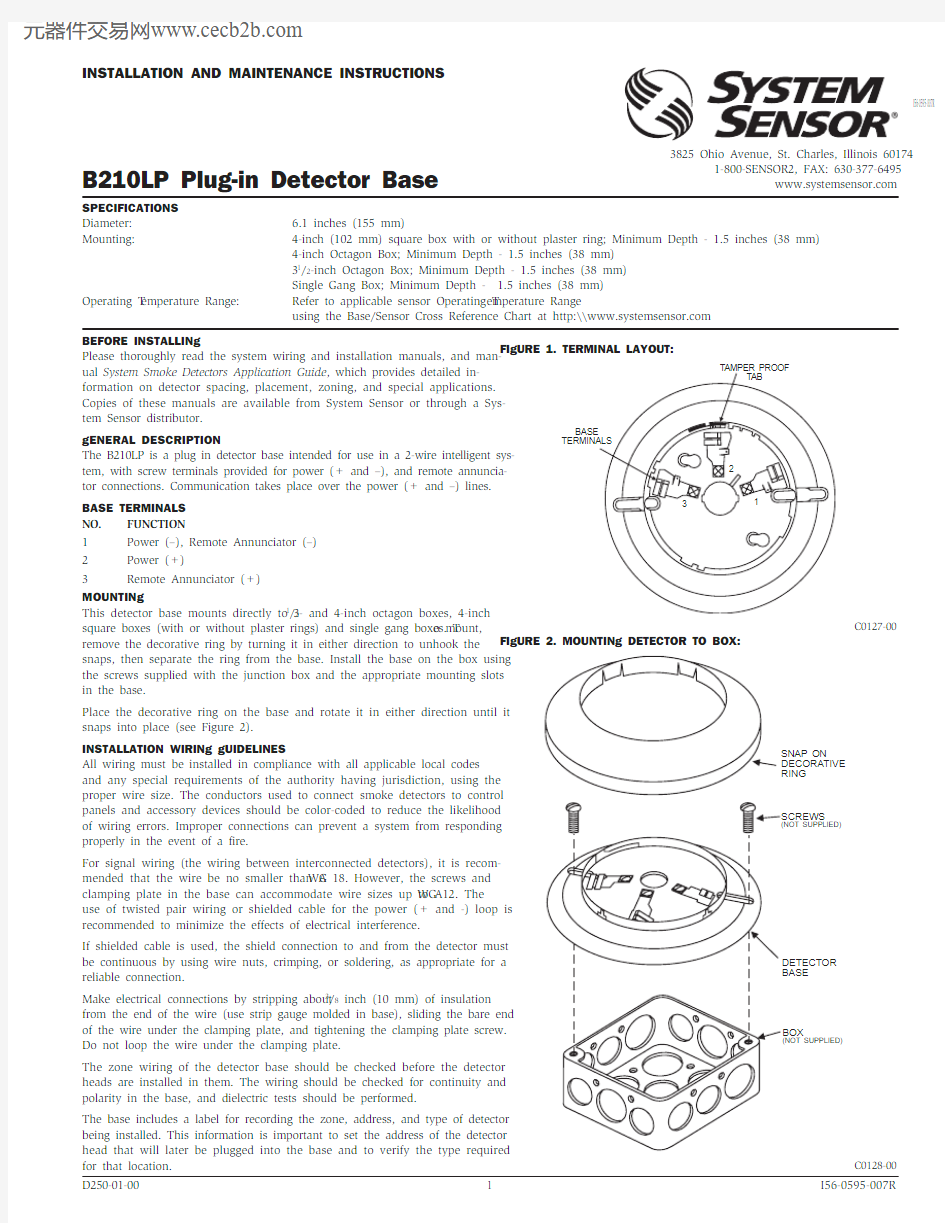
The B210LP is a plug in detector base intended for use in a 2-wire intelligent sys-tem, with screw terminals provided for power (+ and –), and remote annuncia-tor connections. Communication takes place over the power (+ and –) lines.BASE TERMINALS NO. FUNCTION
1 Power (–), Remote Annunciator (–)
2 Power (+)
3 Remote Annunciator (+)MOUNTINg
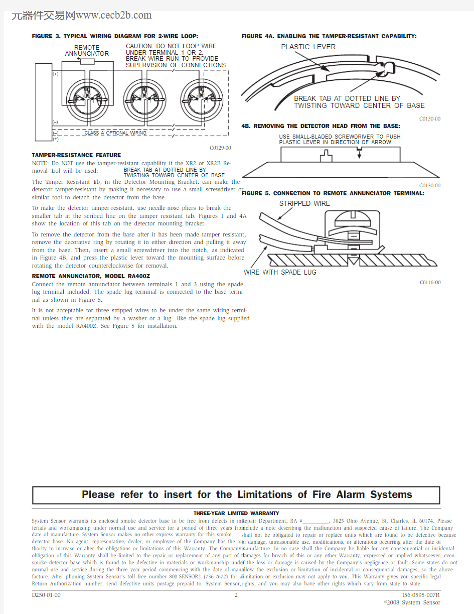
This detector base mounts directly to 31/2- and 4-inch octagon boxes, 4-inch square boxes (with or without plaster rings) and single gang boxes. T o mount, remove the decorative ring by turning it in either direction to unhook the snaps, then separate the ring from the base. Install the base on the box using the screws supplied with the junction box and the appropriate mounting slots in the base.
Place the decorative ring on the base and rotate it in either direction until it snaps into place (see Figure 2).
INSTALLATION WIRINg gUIDELINES
All wiring must be installed in compliance with all applicable local codes and any special requirements of the authority having jurisdiction, using the proper wire size. The conductors used to connect smoke detectors to control panels and accessory devices should be color-coded to reduce the likelihood of wiring errors. Improper connections can prevent a system from responding properly in the event of a fire.
For signal wiring (the wiring between interconnected detectors), it is recom-mended that the wire be no smaller than A WG 18. However, the screws and clamping plate in the base can accommodate wire sizes up to A WG 12. The use of twisted pair wiring or shielded cable for the power (+ and -) loop is recommended to minimize the effects of electrical interference.
If shielded cable is used, the shield connection to and from the detector must be continuous by using wire nuts, crimping, or soldering, as appropriate for a reliable connection.
Make electrical connections by stripping about 3/8 inch (10 mm) of insulation from the end of the wire (use strip gauge molded in base), sliding the bare end of the wire under the clamping plate, and tightening the clamping plate screw. Do not loop the wire under the clamping plate.
The zone wiring of the detector base should be checked before the detector heads are installed in them. The wiring should be checked for continuity and polarity in the base, and dielectric tests should be performed.
The base includes a label for recording the zone, address, and type of detector being installed. This information is important to set the address of the detector head that will later be plugged into the base and to verify the type required for that location.SPECIfICATIONS Diameter: 6.1 inches (155 mm)
Mounting: 4-inch (102 mm) square box with or without plaster ring; Minimum Depth - 1.5 inches (38 mm) 4-inch Octagon Box; Minimum Depth - 1.5 inches (38 mm) 31/2-inch Octagon Box; Minimum Depth - 1.5 inches (38 mm)
Single Gang Box; Minimum Depth - 1.5 inches (38 mm)Operating T emperature Range: Refer to applicable sensor Operating T emperature Range
using the Base/Sensor Cross Reference Chart at http:\\https://www.doczj.com/doc/d612314070.html,
I56-0595-007R
fIgURE 1. TERMINAL LAyOUT:
C0127-00
fIgURE 2. MOUNTINg DETECTOR TO BOx:
C0128-00
fIgURE 3. TyPICAL WIRINg DIAgRAM fOR 2-WIRE LOOP:
CAUTION: DO NOT LOOP WIRE UNDER TERMINAL 1 OR 2.
REMOTE ANNUNCIATOR
detector tamper-resistant by making it necessary to use a small screwdriver or similar tool to detach the detector from the base.
T o make the detector tamper-resistant, use needle-nose pliers to break the smaller tab at the scribed line on the tamper resistant tab. Figures 1 and 4A show the location of this tab on the detector mounting bracket.
T o remove the detector from the base after it has been made tamper resistant, remove the decorative ring by rotating it in either direction and pulling it away from the base. Then, insert a small screwdriver into the notch, as indicated in Figure 4B, and press the plastic lever toward the mounting surface before rotating the detector counterclockwise for removal.
REMOTE ANNUNCIATOR, MODEL RA400Z
Connect the remote annunciator between terminals 1 and 3 using the spade lug terminal included. The spade lug terminal is connected to the base termi-nal as shown in Figure 5.
It is not acceptable for three stripped wires to be under the same wiring termi-nal unless they are separated by a washer or a lug like the spade lug supplied with the model RA400Z. See Figure 5 for installation.
fIgURE 4A. ENABLINg ThE TAMPER-RESISTANT CAPABILITy:
C0130-00
4B. REMOvINg ThE DETECTOR hEAD fROM ThE BASE:
USE SMALL-BLADED SCREWDRIVER TO PUSH PLASTIC LEVER IN DIRECTION OF ARROW
C0130-00
fIgURE 5. CONNECTION TO REMOTE ANNUNCIATOR TERMINAL:
C0116-00
D250-01-00 2 I56-0595-007R ?2008 System Sensor
ThREE-yEAR LIMITED WARRANTy
System Sensor warrants its enclosed smoke detector base to be free from defects in ma-terials and workmanship under normal use and service for a period of three years from date of manufacture. System Sensor makes no other express warranty for this smoke detector base. No agent, representative, dealer, or employee of the Company has the au-thority to increase or alter the obligations or limitations of this Warranty. The Company’s obligation of this Warranty shall be limited to the repair or replacement of any part of the smoke detector base which is found to be defective in materials or workmanship under normal use and service during the three year period commencing with the date of manu-facture. After phoning System Sensor’s toll free number 800-SENSOR2 (736-7672) for a Return Authorization number, send defective units postage prepaid to: System Sensor, Repair Department, RA #__________, 3825 Ohio Avenue, St. Charles, IL 60174. Please
include a note describing the malfunction and suspected cause of failure. The Company shall not be obligated to repair or replace units which are found to be defective because of damage, unreasonable use, modifications, or alterations occurring after the date of
manufacture. In no case shall the Company be liable for any consequential or incidental damages for breach of this or any other Warranty, expressed or implied whatsoever, even if the loss or damage is caused by the Company’s negligence or fault. Some states do not allow the exclusion or limitation of incidental or consequential damages, so the above
limitation or exclusion may not apply to you. This Warranty gives you specific legal rights, and you may also have other rights which vary from state to state.
Please refer to insert for the Limitations of Fire Alarm Systems