毕业设计(论文)外文资料翻译
学院:机械工程学院
专业:机械设计制造及其自动化
姓名:尤兴亚
学号: 0902070438 外文出处:Corresponding Author
cnlwl@https://www.doczj.com/doc/dd18155682.html,
附件: 1.外文资料翻译译文;2.外文原文。
起重机液压系统支腿的智能故障诊断研究
李万里, 黄佳奎, 王鹏晨, 朱福明
机械工程学院,同济大学,上海201804,中国;物流工程学院,上海海事大学,上海200135,中国;
摘要:随着起重机液压系统越来越复杂,要求故障诊断更加快速和全面。根据起重机支腿液压系统的结构特点,本文提出了一种快速而广泛的硬件和软件体系结构模型的空调监测与故障诊断系统。在本文中,树的诊断方法和模糊神经网络理论的应用为液压系统的故障诊断提供了理论基础以及实现方法。
关键字:起重机,故障诊断,神经网络
1、引言
汽车起重机是一种重要的工程机械。以其日趋复杂的结构和功能,它更倾向于复杂的问题,所以很难诊断起重机支架液压系统的故障。在这样的场景中,一个单一的理论或方法,无论是聪明还是经典的都不足以实现全面、准确、快捷的故障诊断。然而,结合了两个或更多经典和智能的方法,它可能是一个准确、快速的折中诊断方法。本文利用联合诊断算法(模糊神经网络的故障诊断)为支架的起重机液压系统诊断。该算法实现了硬件平台和软件模型的联合诊断,实现了状态监测和故障诊断液压系统。
2、建立基于模糊神经网络稳定支撑的液压系统的故障诊断模型
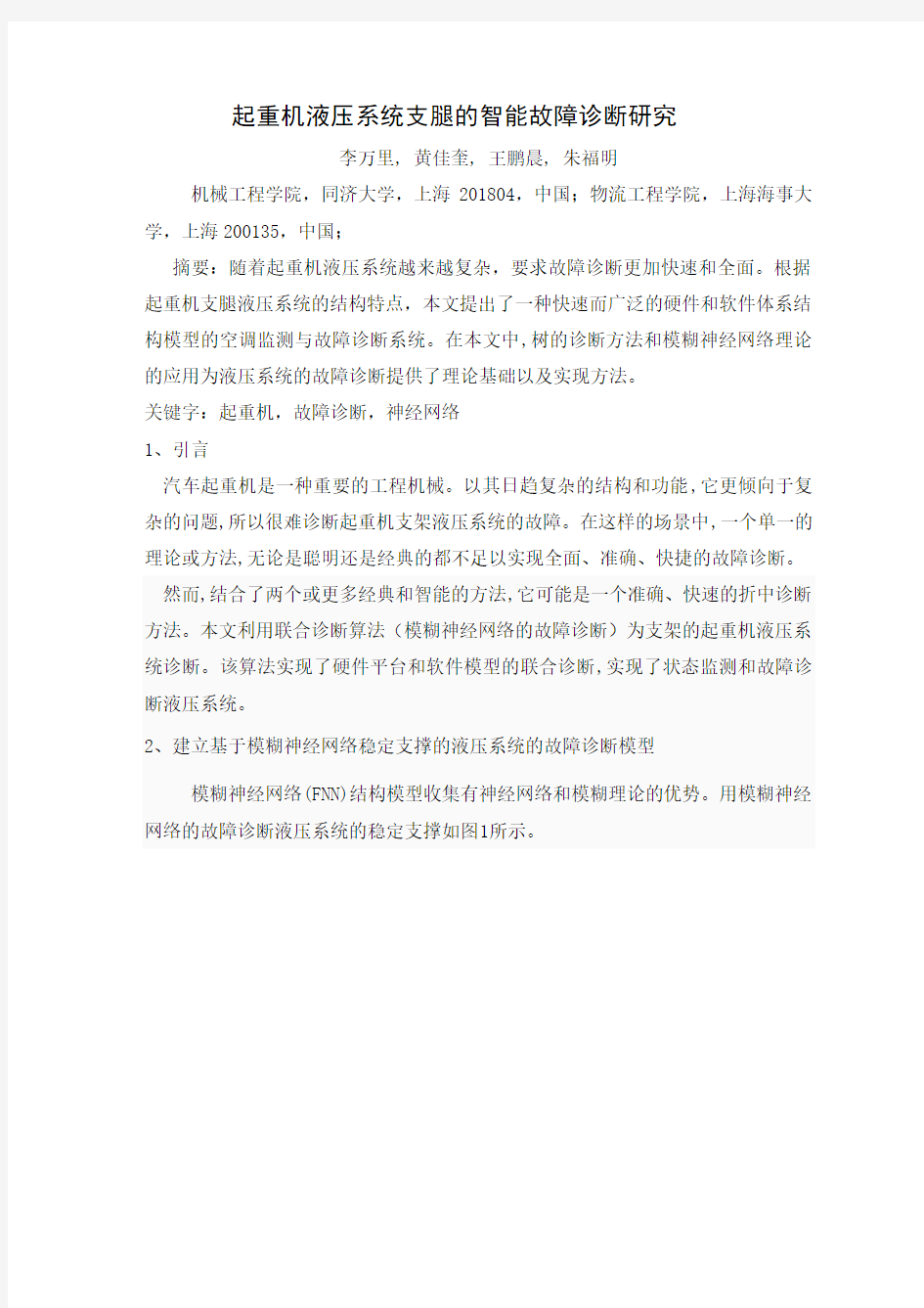
模糊神经网络(FNN)结构模型收集有神经网络和模糊理论的优势。用模糊神经网络的故障诊断液压系统的稳定支撑如图1所示。
图1结构模型的模糊神经网络算法
基于模糊神经网络的BP(反向传播)神经网络,采用串联方式与模糊系统。输入和输出的网络是模糊量和成员的一些特性和一些模型。网络结构分为五层,输入层、隐层、模糊层、输出层、模糊化消除层。
输入层是第一层网络。这层接收输入特征信号从外面直接传输之前的特征信号到二层——模糊神经元。转移重量是1。节点的数量在输入层取决于数量的特征信号的诊断。
模糊层是第二层的网络。它的功能是计算成员的输入特性信号,属于模糊集合中的每个变量值,根据隶属函数的模糊子集。模糊化后,每个输入层节点对应于三个模糊层节点,代表高边,正常和低侧分别。因此,节点的数量是3倍数量的输入节点。
隐藏层是第三层网络。它是用于实现从输入变量模糊值映射到输出变量的模糊值。激活函数使用是乙状结肠函数。节点的数量是两倍数量的模糊层节点,根据柯尔莫哥洛夫定理。在培训过程中,调整可以根据不同程度的准确性。
输出层是第四层的网络。每个节点对应的每个故障引起的液压子系统。输出值是会员大小隶属于故障原因。节点的数量对应于多种原因引起的典型故障的液压系
统。模糊化消除层是第五层的网络。阐述了模糊结果输出层和输出明确的诊断结果。清晰的计算是基于最小阈值原则(会员价值的故障组件应大于某一阈值,这是定义在调试。的值应该设置为一个适当的值。一个大型会员价值可能会导致一些错误的无知,而小值可能导致假警报的缺点)。
特征信号的液压系统工况选择如下:油温的液压系统,油位在罐、油的压力和流量泵出口、操作压力和泄油压力的水平和垂直液压缸的每条腿。监测信号的分布如图2所示。
1-温度传感器;2-传感器;3-压力/流量传感器;4-压力传感器图2特征信号的工作状态的起重机液压系统稳定支撑
除了工作状态的特征信号,信号的选择,包括控制信号拉伸/收缩水平/垂直腿拉伸/收缩,联动水平/垂直腿和选择信号的半拉伸/所有段水平腿等。
(1)、油温
当支腿系统正常工作,油的温度通常是40 ~ 60℃。但当故障发生时,液压油温度可能经常波动。这可能是由于泄漏的齿轮泵;泄漏或粘腿的液压缸;泄漏或太高的调整压力安全阀等。
(2)油位油箱
当支腿系统工作正常,油位根据一定的方式不断变化的。当在系统中遇到的一些液压元件的泄漏或其他故障时,系统的液压油位会根据工作条件改变。
(3)齿轮泵的出口压力油
液压油压力泵的出口是由外部负载。如果在系统遇到故障时,出口油压力会发生剧烈的变化。
(4)输出石油流动的齿轮泵
如果液压泵遇到故障,将在很长一段时间内无法达到一个稳定的范围内输出油流。
(5)水平杆的液压缸的油压
当支腿水平方向伸展,油压杆少液压缸取决于电阻的腿。阻力包括摩擦阻力和液压阻力杆少液压缸。当腿拉开水平,油压杆少液压缸取决于石油缓解压力的方式回油。当腿水平方向伸展,如果泄漏发生在水平液压缸或换向阀控制气缸,油压力杆少液压缸将低于正常范围。因此,腿不能移动或移动缓慢。当腿拉开水平,如果梗阻发生背压值或油过滤器、油压力杆少液压缸将超过正常范围。因此,腿不能返回。
(6)水平杆液压缸的油压
当双腿伸出水平,取决于杆液压缸的油压油溢流压力回油方式。当腿抽到回水平,杆液压缸的压力油的电阻取决于的leg.The电阻包括摩擦阻力和杆液压缸的液压阻力。当腿伸出水平,如果阻塞发生背压阀或油过滤器,油压力杆液压缸将在上述正常范围。因此,双腿不能移动或移动缓慢。当腿抽到回水平,如果发生泄漏的水平液压缸或换向阀控制气缸,杆液压缸的油的压力将低于在正常范围。因此,腿不能返回。
上面的分析描述信号特征之间的关系,故障现象和故障原因。手术期间,每个特征信号与许多现象和原因的故障而引起的故障现象或每个可能是由大量的信号特征。
正如上面提到的,我们可以诊断故障原因的一些模糊神经网络基于传感器我们已经。失败原因如下:缺乏石油、水力泵衰竭,安全阀失效,电磁换向阀故障,双向液压锁故障,泄漏的水平液压缸的腿,泄漏的垂直液压缸的腿,妨碍背压阀和油过滤器等。
根据相关的设计和调谐的液压系统中的参数,特征信号参数的正常范围和严重程度的可能偏差,得到(如表1所示)。
表1正常范围内的液压系统的特征信号
2、2模糊化过程和选择隶属函数的特征信号的液压系统
根据测量的每个特征信号参数的液压系统,我们可以知道如果参数是正常的,偏小或偏大。至于隶属度的范围,即隶属度故障原因和故障现象之间,它被定义为相应的隶属函数。
模糊隶属函数的相关性,实际情况会影响诊断结果直接。因此,确定隶属函数的关键是整个故障诊断。在许多情况下,根据实际情况,最简单有效的方法是使用一些常见的隶属函数来表达一些模糊变量的约。根据过去的经验和实际变化的参数,本文选用常用的贝尔隶属函数作为一个正常状态的隶属函数、隶属度函数下z型是偏小的状态的隶属度函数和了z型隶属函数作为隶属函数偏大的状态。
考虑到没有明显边界的这些模糊概念的偏小,正常和偏小,重叠部分必须设置为这些隶属函数反映在模糊集的隶属函数曲线。选择合适的重叠率是一个重要的因素来保证诊断的可靠性。关于过去的经验,重叠率的隶属函数的文章被选中在0.2和0.6之间。
考虑的数量,形状,位置,分布,重叠率,等后,我们确定信号参数支持的特性(图3,4,5,6,7和8)的隶属度函数的液压系统。
根据实际情况的操作,我们已经调整了参数的隶属函数。
图3隶属函数的液压油的温度图4隶属函数的油位
图5隶属函数的石油释放压力图6隶属函数的工作压力的液压油缸
图7隶属函数的工作流程的液压油缸图8隶属函数的控制油压力
模糊化过程特征信号的参数是传递精确的输入值的特征信号参数模糊隶属度值。首先,输入值的特征信号参数的分布范围,每个范围偏大,偏小,正常传输。其次,进行了模糊化过程的特征信号参数,已被转移到某些域范围。这个过程将使原来的精确的输入到模糊隶属度值介于0 ~ 1。
2.3培训与学习的模糊神经网络模型的液压系统
我们使液压系统的特征信号的稳定支撑作为模糊神经网络的输入和相应的故障原因的系统作为模糊神经网络的输出。培训和学习的过程显示在图9。
每个操作循环包括以下内容:
首先,它读取训练样本的数据和从知识数据库中的各特征参数的范围内,并且
操作输入故障的样本数据的模糊化过程。第二,它写的模糊化过程数据和预期的输出故障样本数据的神经网络。然后计算每层节点的输出由神经网络。第三,计算输出层节点的实际输出与期望输出之间的误差,并确定,如果训练结果满足精度要求。
如果满足精度要求或培训的最大数量,它存储了本次培训的网络权重和阈值转化为知识数据库,前结束训练过程中。
如果精度要求或不符合的最大数目的培训,它实现向后传输计算减少错误的方向上,并调整输出层和隐层的权值和阈值。在那之后,它实现了一个新的正向传输计算来计算的输出错误之前,下一个比较的精度要求和最大的培训。重复的步骤,上述步骤,直到满足两个准则。
3、实施监测与故障诊断
图10显示了状态监测与故障诊断的软件架构。我们采用自上而下的方法,为软件开发。该软件被划分成单独的模块,方便调试,代码维护和扩展。
图11显示硬件架构的监测与故障诊断。由监测传感器,PLC控制系统,数据采集板和车载电脑或PC等硬件设置
图10、软件架构
图11、硬件架构
图12、显示了用户界面的硬件系统的模糊神经网络故障诊断。
用户界面被分为3个区域在视觉上,即实时参数监视区域,诊断报告和维护上的建议示区域和工具按钮区域。
诊断报告包括诊断时间、诊断算法、故障代码、故障ID现象,故障定位和故障原因。维修建议由机器操作的建议在文字或图形。
工具按钮包括初步诊断按钮,雷达视图“按钮,停止诊断按钮和退出按钮。初步诊断按钮和停止的诊断按钮设计联锁的方式。雷达视图“按钮会导致失败的概率诊断系统的雷达视图。
在这个过程的状态监测和故障诊断,故障的可能性和概率,每个断层影响整体故障显示在雷达视图i如(图13)。诊断的过程中,所有的可能性的每个故障都保存到雷达数据表。当雷达监测,雷达数据表显示和刷新的数据变化,这是同步的,诊断结果。
4、结论
介绍了我们设计和实现的故障诊断模型的模糊神经网络的起重机液压系统稳定支撑。一个方法相结合的模糊理论和人工神经网络算法。模型的输入和输出信号,输入信号的范围,选择隶属度函数和模糊化处理是讨论等。实现在软件和硬件平台进行了阐述。本文阐明了理论基础,导致一个实现方法的监测和故障诊断液压系统起重机支架。这个系统也可以用于其他类似的液压系统,如盾构液压系统,液压系统装载机机等。
参考文献
[1] Jia Hongxia, Li Wanli, Yu Haojie. Dynamic analysis and modeling of correction system for the hydraulic grab of underground continuous wall[J], Journal of Tongji University: Natural Science Edition,2009,37(10): 1393.
[2] Lu Jiang. Analysis and countermeasures of the causes of accident on the operation of lifting machinery[J],Construction Decoration, 2009,10(67):11
一13.
[3] Liu Binpeng. The current situation and development trend of engineering machinery industry of our country[Z], The Management Learning Nets, 2010,3.
[4]Zhao Keli, Wen Yuming. The application of electronic technology in the hydraulic excavator[J], Construction Machinery, 1997(3):33-34.
[5] Wang Shirring, Yang Weimin, Li Tianshi, etc. New technology,new structure and development trend of engineering machinery of foreign country[J], Engineering Machinery, 2004(1):61-66.
[6]Wang Shirring. The current situation and development trend of failure monitoring diagnosis technology of the hydraulic system of engineering machinery[J], Machine and Hydraulic, 2009,37(2):175-180.
附件2:外文原文
R esearch of Intelligent F ault D iagnosis for H ydraulic S ystem of
C ranes O utriggers
Li Wanli'*, Hua Jiakui', Wang Pengchen', Zhu Fumin 2
1 .College of Mechanical Engineering, Ton自i University, Shanghai 201804, China
2.Logistics Engineering College, Shanghai Maritime University, Shanghai 200135, China
*Corresponding Author; cnlwl@https://www.doczj.com/doc/dd18155682.html,
A bstract The complexity of hydraulic systems of crane outriggers is growing, which demands the fault diagnosis of the systems to be faster and comprehensive. Based on the structural characteristics of the hydraulic systems of crane outriggers, this paper proposes a rapid and extensive hardware and software architecture model of conditioning monitoring and fault diagnosis system. In this paper, tree diagnostic method and fuzzy neutral network theory is applied; the theoretical basis as well as the implementation method for this and similar hydraulic systems' fault diagnosis is provided.
K eywords Cranes, Fault diagnosis, Neural network
1 Introduction
Truck crane is an important model of engineering machinery.With its growing complexity in structure and function, it is more prone to complex troubles, so that it is harder to diagnosis the fault for hydraulic system of cranes outriggers. In such scenarios, a single theory or method, whether classic or smart, is far from sufficient to achieve fault diagnosis that are comprehensive, accurate and fast.
Nevertheless, the combination of classic method and smart, two smart methods or more, may make a good compromise between the diagnosis' accuracy and speed. With the above understanding, this paper utilizes a combined diagnosis algorithm, which is the fuzzy neural network, for the fault diagnosis of hydraulic system of crane outriggers. The algorithm is implemented with a hardware platform and a software model of the diagnosis that realized the condition monitoring and fault diagnosis of the hydraulic system.
2 Establishment of fault diagnosis model of the hydraulic system of outriggers based on fuzzy neural network
The fuzzy neural network (FNN) structure model collects the advantages of neural network and fuzzy theory. The FNN used by fault diagnosis of the hydraulic system of outriggers in this paper is shown in figure 1.
The FNN is based on BP (Back Propagation) artificial neural network and uses the tandem way with fuzzy system. The input and output of the network are fuzzy quantity and membership of some features and some models. The network structure is divided into five layers, input layer, fuzzy layer,hidden layer, output layer, fuzzification elimination layer.
Fig. 1 Structure model of FNN algorithm
Input layer is the first layer of the network. This layer receives input characteristic signal from outside before directly transports the characteristic signal to the second floor--fuzzy neurons. The transfer weight is 1. The number of nodes in the input layer depends on the number of characteristic signal of the diagnosis.
Fuzzy layer is the second layer of the network. Its function is to calculate membership of the input characteristics signal that belongs to fuzzy set of each variable value, according to the membership functions of the fuzzy subsets. After fuzzification, each input layer node corresponds to three fuzzy layer nodes, representing the high side, normal and the low side respectively. Therefore, the number of nodes is 3 times of the number of input nodes.
Hidden layer is the third layer of the network. It is used to implement the mapping from input variable fuzzy value to the output variable fuzzy value. The activation function used is Sigmoid function. The number of the nodes is two times of the number of fuzzy layer nodes, according to theorem of Kolmogorov. During the training process, adjustments can be made according to different level of accuracy.
Output layer is the fourth layer of the network. Each node of it is corresponding to each fault causes of the hydraulic subsystem. Output value is the membership size affiliated to the fault causes. The number of the nodes corresponds to the number of causes of typical faults of the hydraulic system. Fuzzification Elimination layer is the fifth layer of the network. It clarifies the fuzzy results of the output layer and outputs the definite diagnosis results. The clarity calculation is based on minimum threshold value principle (Membership value of fault components should be greater than some thresholds, which is defined in debugging. The value should be set to an appropriate value. A large membership value might lead to the ignorance of some faults while a small value may cause false alarms of faults).
Fig. 2 Characteristic signal of work condition of the hydraulic system of cranes outriggers 1-Temperature sensor; 2-Level sensor; 3-Pressure/flow sensor; 4-Pressure sensor
The characteristic signal of the working condition of the hydraulic system is chosen as follows: the oil temperature of the hydraulic system, oil level in tank, oil pressure and flow of pump exit, operating pressure and oil-relief pressure of the horizontal and vertical hydraulic cylinder of each leg. The distribution of monitoring signal is shown in figure 2.
Besides the characteristic signal of the working condition,other signals are chosen, including control signal of stretch/shrinkage of Horizontal/vertical legs, linkage stretch /shrinkage of Horizontal/vertical legs and selection signal of half a stretch/all stretch of Horizontal legs, etc.
(1)The oil temperature
When the leg system works properly, the oil temperature is usually 40~60 ℃.But when fault occurs, the hydraulic oil temperature might experience fluctuations. This might be caused by: leakage of gear pump; leakage or stuck of a leg hydraulic cylinder; leakage or too high adjustment pressure of relief valve, etc.
(2) Oil level in tank
When the leg system works properly, oil level keeps changing according to a certain fashion. When some hydraulic components in the system encounter leakage or other faults,the system's hydraulic oil level will change according to the condition of work.
(3)The oil pressure on gear pump exit
Hydraulic oil pressure on pump exit is determined by external load. If the system encounters faults, the outlet pressure can experience drastic change.
(4) Output oil flow of gear pump
If the hydraulic pump encounters faults, the output oil flow will not be able to reach a stable range
within a long time.
(5)Oil pressure of the horizontal rod-less hydraulic cylinder
When the legs stretched out horizontally, oil pressure of rod-less hydraulic cylinder depends on the resistance of the leg.The resistance includes friction resistance and hydraulic resistance of rod-less hydraulic cylinder. When the legs draw back horizontally, oil pressure of rod-less hydraulic cylinder depends on the oil-relief pressure of back-oil-way. When the legs stretched out horizontally, if leakage happens to the horizontal hydraulic cylinder or the reversing valves that controls the cylinder, the oil pressure of the rod-less hydraulic cylinder will be below the normal range. Consequently, the legs cannot move or move sluggishly. When the legs draw back horizontally, if obstruction happens to the back-pressure value or oil filters, the oil pressure of the rod-less hydraulic cylinder will be above the normal range. Consequently, the legs cannot return.
(6)Oil pressure of the horizontal rod hydraulic cylinder
When the legs stretched out horizontally, oil pressure of rod hydraulic cylinder depends on the oil-relief pressure of back-oil-way. When the legs draw back horizontally, oil pressure of rod hydraulic cylinder depends on the resistance of the leg.The resistance includes friction resistance and hydraulic resistance of rod hydraulic cylinder. When the legs stretched out horizontally, if obstruction happens to back-pressure-valve or oil filters, the oil pressure of the rod-less hydraulic cylinder will be above the normal range. Consequently, the legs cannot move or move sluggishly. When the legs draw back horizontally, if leakage happens to the horizontal hydraulic cylinder or the reversing valves that controls the cylinder, the oil pressure of the rod hydraulic cylinder will be below the normal range. Consequently, the legs cannot return.
The vertical hydraulic cylinder has the similar theory with the horizontal ones.
The above analysis describes the relationship between characteristic signals, fault phenomena and fault causes.During the operation, each characteristic signal is related to many phenomena and causes of fault while each phenomenon or cause of faults may be indicated by many characteristic signals.
As mentioned above, we can diagnosis some failure causes by fuzzy neural network based on the sensor we have. The failure causes are as fellows: shortage of oil, hydraulic pump failure, relief valve failure, electromagnetic reversing valve failure, bi-directional hydraulic lock failure, leakage of horizontal hydraulic cylinder of legs, leakage of vertical hydraulic cylinder of legs, and obstruction of back pressure valve and oil filters, etc.
According to the related design and tuning of the parameters of the hydraulic system, the normal range of characteristic signal parameters and the severity of the possible deviation are obtained (as shown in table 1).
Table 1 Normal range of characteristic signal of the hydraulic system
2.2 Fuzzification process and selection on membership functions of characteristic signal of the hydraulic system
According to the measurement of each characteristic signal parameter of hydraulic system, we can know if the parameter is normal, slants small or slants big. As for the membership degree in the range, namely the membership degree between fault causes and fault phenomena, it is defined by the corresponding membership functions.
The relevance between fuzzy membership functions and actual situation affects the diagnosis results directly. Therefore, to determine the membership function is the key to
the whole fault diagnosis. In many cases, according to the actual situation, the most simple and effective method is to use some common membership function to approximately express some fuzzy variables. According to past experience and actual change of parameters, this paper selects the commonly-used bell membership functions as a normal state of membership functions, the down-Z-type membership functions as slants small state of membership functions and up-Z-type membership functions as slants big state of membership functions.
Considering that there is no obvious boundary of these fuzzy concepts of slants small, normal and slants small, overlapping part must be set for these membership functions reflected in the membership function curve of fuzzy sets. Choosing the right overlap rate is an important factor to guarantee the reliability of the diagnosis. With reference to past experience, the overlap rate of the membership functions of this paper was selected between 0.2 and 0.6.
After a comprehensive consideration of the number, shape,position distribution, overlapping rate and so on, we determined membership functions of characteristic signal parameters of the hydraulic system of outriggers (Figs. 3, 4, 5,6, 7 and 8).
According to actual situation of the operation, we have adjusted the parameters for the membership functions.
Fig. 3 Membership functions of the temperature of hydraulic oil
Fig. 4 Membership functions of the oil level
Fig. 5 Membership functions of the oil relief pressure
Fig. 6 Membership functions of the work pressure of hydrocylinder
Fig. 7 Membership functions of the work flow of hydrocylinder
Fig. 8 Membership functions of the control oil pressure
Fuzzification process of characteristic signal parameters is to transfer the precise input values of characteristic signal parameter to fuzzy membership value. Firstly, the input values of characteristic signal parameter to each range, the range of slants small, slants big, normal are transferred. Secondly, fuzzification process is conducted to the characteristic signal parameters that have been transferred to certain domain range. The process would turn the original precise input into fuzzy membership value between 0~1.
2.3 Training and learning of fuzzy neural network model of the hydraulic system
We make the characteristic signal of the hydraulic system of outriggers as the fuzzy neural network's input and the corresponding failure causes of system as fuzzy neural network's output. Then we set up network model of fault diagnosis respectively as figure 1 .The process of training and learning are shown in fig. 9.
Each operation loop consists the following:
Firstly, it reads training sample data and the range of each feature parameter from the knowledge databases, and operates fuzzification process with the sample data of input fault.Second, it writes the fuzzification process data and the expected output fault samples data into the neural network.Then it calculates the output of each layer node by the neural network. Third, it calculates the error between actual output of output layer node and expected output, and determines if the training results meet the requirement of accuracy.
If precision requirement or to the maximum number of training are met, it stores this training's network weights and threshold into knowledge database, before ends this training process.
If the precision requirement or to the maximum number of trainings are not met, it implements backward transmission calculation on the direction of reducing the error, and adjusts the weights and threshold of output layer and hidden layer. After that, it implements a new forward transmission calculation to calculate the output error before next comparison to the precision requirements and maximum number of trainings. Repeat the steps the above steps until the two criteria are met.
3 Implementation of the monitoring and fault diagnosis
Fig. 10 shows the software architecture of condition monitoring and fault diagnosis.
We adopt the top-down approach for software developing. The software is divided into separate modules, which is convenient for debugging, code maintaining and extensions.
Fig.l l shows the hardware architecture of the monitoring and fault diagnosis. The hardware set consists of monitoring sensor, PLC controller system, data acquisition boards and vehicle-mounted computer or pc, etc.
Fig. 10 Software architecture
Fig. 11 Hardware architecture
Fig. 12 shows the user interface of the hardware system of the fuzzy neural network fault diagnosis.
User interface is divided into 3 areas visually, namely the real-time parameters monitoring area, diagnosis report and maintenance suggestion display area and tools button area.
Diagnosis report consists of diagnosis time, diagnosis algorithm ID, fault code, fault
机械设计 摘要:机器是由机械装置和其它组件组成的。它是一种用来转换或传递能量的装置,例如:发动机、涡轮机、车辆、起重机、印刷机、洗衣机、照相机和摄影机等。许多原则和设计方法不但适用于机器的设计,也适用于非机器的设计。术语中的“机械装置设计”的含义要比“机械设计”的含义更为广泛一些,机械装置设计包括机械设计。在分析运动及设计结构时,要把产品外型以及以后的保养也要考虑在机械设计中。在机械工程领域中,以及其它工程领域中,所有这些都需要机械设备,比如:开关、凸轮、阀门、船舶以及搅拌机等。 关键词:设计流程设计规则机械设计 设计流程 设计开始之前就要想到机器的实际性,现存的机器需要在耐用性、效率、重量、速度,或者成本上得到改善。新的机器必需具有以前机器所能执行的功能。 在设计的初始阶段,应该允许设计人员充分发挥创造性,不要受到任何约束。即使产生了许多不切实际的想法,也会在设计的早期,即在绘制图纸之前被改正掉。只有这样,才不致于阻断创新的思路。通常,还要提出几套设计方案,然后加以比较。很有可能在这个计划最后决定中,使用了某些不在计划之内的一些设想。 一般的当外型特点和组件部分的尺寸特点分析得透彻时,就可以全面的设计和分析。接着还要客观的分析机器性能的优越性,以及它的安全、重量、耐用性,并且竞争力的成本也要考虑在分析结果之内。每一个至关重要的部分要优化它的比例和尺寸,同时也要保持与其它组成部分相协调。 也要选择原材料和处理原材料的方法。通过力学原理来分析和实现这些重要的特性,如那些静态反应的能量和摩擦力的最佳利用,像动力惯性、加速动力和能量;包括弹性材料的强度、应力和刚度等材料的物理特性,以及流体润滑和驱动器的流体力学。设计的过程是重复和合作的过程,无论是正式或非正式的进行,对设计者来说每个阶段都很重要。 最后,以图样为设计的标准,并建立将来的模型。如果它的测试是符合事先要
起重机液压系统使用注意事项示范文本 In The Actual Work Production Management, In Order To Ensure The Smooth Progress Of The Process, And Consider The Relationship Between Each Link, The Specific Requirements Of Each Link To Achieve Risk Control And Planning 某某管理中心 XX年XX月
起重机液压系统使用注意事项示范文本使用指引:此管理制度资料应用在实际工作生产管理中为了保障过程顺利推进,同时考虑各个环节之间的关系,每个环节实现的具体要求而进行的风险控制与规划,并将危害降低到最小,文档经过下载可进行自定义修改,请根据实际需求进行调整与使用。 起重机是以液压为动力的,设有各种液压装置。因 此,如不确实遵守运转维护规则,不仅不可能充分发挥应 有的性能,还将缩短机件的使用寿命。因此,在进行作业 时,必须切实遵守以下的事项。 1.作业前,应由油箱液位窗口确定液压油是否按规定加 足,低于规定刻线以下,则必须加以补充。加油时,一定 要经过加油滤网注入,并十分注意不能混进不同牌号的油 或水等不纯特质。 2.滤油器滤芯在工作250h后,应进行检查,必要时进 行清洗或更换。 3.液压油箱应每隔半个月从底部放油口清除水分和杂质 一次,并每隔一年(或工作满2000h)更换全部液压油(在油
液未发生变质的情况下,可适当延长换油周期)。当起重机在使用环境特别恶劣的情况下作业时,油液的更换周期应相应缩短。 4.液压系统的各种阀门在出厂前已经充分试验,并已调整好压力和流量,切不可随便触动。 5.各种机件,特别是液压系统各装置,都切忌污垢附着。在作业以后,一定要把灰尘、油污清除干净。 请在此位置输入品牌名/标语/slogan Please Enter The Brand Name / Slogan / Slogan In This Position, Such As Foonsion
设计及说明结果一、25吨汽车起重机伸缩臂架的设计 箱型吊臂连接尺寸的确定包含下列的容:1)吊臂根部铰点位置 的确定;2)吊臂各节尺寸的确定;3)变幅油缸铰点的确定。 1、吊臂根部铰点位置的确定 基本臂工作长度和吊臂最大工作长度的确定: 由图2.1可知,设为工作长度,则有 图2.1 三铰点有关尺寸图
式中:H—基本臂的起升高度,。 b—吊钩滑轮组最短距离,取。 、—根部铰点和头部滑轮轴心离吊臂基本截面中心线的距离,并带有符号。由于此项数值较小,所 以计算时可以忽略不计。 —吊臂仰角,取。 h—根部铰接点离地距离,取。 吊臂根部离铰点的距离e —最小工作幅度,取。 吊臂根部铰点离回转平面的高度 —回转支承装置的高度, —起重机汽车底盘的高度, 主吊臂最大长度 —最长主臂起升高度, a,r,b,h同上。 2、吊臂各节尺寸的确定 主吊臂的最长长度是由基本臂结构长度和外伸长度所组成。 、、—各节臂的伸缩长度,在设计中伸缩长度往往取
同一数值,即。外伸长度。 、、—为二、三、四节臂缩回后外漏部分的长度,在 计算时取同一数值(a=0.25m) 若假设为臂头滑轮中心离基本臂端面的距离,则基本臂结构长度加上即为基本臂的工作长度。 所以有 从中可以求出 k—吊臂的节数。 —主臂最大长度,初取35m。 —主臂最小长度,初取11m。 通常搭接长度应该短些,以减轻吊臂重量。但是,太短将搭接部分反力增大了,引起搭接部分吊臂的盖板或侧板局部失稳,同时,也使吊臂的间隙变形增大。因此搭接部分要根据实际经验和优化设计而定,一般为伸缩臂外伸长度的1/4—1/5(吊臂较长者取后者,较短者取前者,同步伸缩者可取后者)。 从而搭接长度为 在第i节臂退回后,除外露部分长度a外,在前节(i-1)节臂中的长度加上伸出后仍在前节臂中的那部分搭接长度。第i节臂插在前节臂的长度为(),设第i节臂的结构长度为,则
中英文对照外文翻译 汽车变速器设计 我们知道,汽车发动机在一定的转速下能够达到最好的状态,此时发出的功率比较大,燃油经济性也比较好。因此,我们希望发动机总是在最好的状态下工作。但是,汽车在使用的时候需要有不同的速度,这样就产生了矛盾。这个矛盾要通过变速器来解决。 汽车变速器的作用用一句话概括,就叫做变速变扭,即增速减扭或减速增扭。为什么减速可以增扭,而增速又要减扭呢?设发动机输出的功率不变,功率可以表示为 N = w T,其中w是转动的角速度,T 是扭距。当N固定的时候,w与T是成反比的。所以增速必减扭,减速必增扭。汽车变速器齿轮传动就根据变速变扭的原理,分成各个档位对应不同的传动比,以适应不同的运行状况。 一般的手动变速器内设置输入轴、中间轴和输出轴,又称三轴式,另外还有倒档轴。三轴式是变速器的主体结构,输入轴的转速也就是发动机的转速,输出轴转速则是中间轴与输出轴之间不同齿轮啮合所产生的转速。不同的齿轮啮合就有不同的传动比,也就有了不同的转速。例如郑州日产ZN6481W2G型SUV车手动变速器,它的传动比分别是:1档3.704:1;2档2.202:1;3档1.414:1;4档1:1;5档(超速档)0.802:1。 当汽车启动司机选择1档时,拨叉将1/2档同步器向后接合1档
齿轮并将它锁定输出轴上,动力经输入轴、中间轴和输出轴上的1档齿轮,1档齿轮带动输出轴,输出轴将动力传递到传动轴上(红色箭头)。典型1档变速齿轮传动比是3:1,也就是说输入轴转3圈,输出轴转1圈。 当汽车增速司机选择2档时,拨叉将1/2档同步器与1档分离后接合2档齿轮并锁定输出轴上,动力传递路线相似,所不同的是输出轴上的1档齿轮换成2档齿轮带动输出轴。典型2档变速齿轮传动比是2.2:1,输入轴转2.2圈,输出轴转1圈,比1档转速增加,扭矩降低。 当汽车加油增速司机选择3档时,拨叉使1/2档同步器回到空档位置,又使3/4档同步器移动直至将3档齿轮锁定在输出轴上,使动力可以从轴入轴—中间轴—输出轴上的3档变速齿轮,通过3档变速齿轮带动输出轴。典型3档传动比是1.7:1,输入轴转1.7圈,输出轴转1圈,是进一步的增速。 当汽车加油增速司机选择4档时,拨叉将3/4档同步器脱离3档齿轮直接与输入轴主动齿轮接合,动力直接从输入轴传递到输出轴,此时传动比1:1,即输出轴与输入轴转速一样。由于动力不经中间轴,又称直接档,该档传动比的传动效率最高。汽车多数运行时间都用直接档以达到最好的燃油经济性。 换档时要先进入空档,变速器处于空档时变速齿轮没有锁定在输出轴上,它们不能带动输出轴转动,没有动力输出。 一般汽车手动变速器传动比主要分上述1-4档,通常设计者首先确定最低(1档)与最高(4档)传动比后,中间各档传动比一
附录A Lathe fixture design and analysis Ma Feiyue (School of Mechanical Engineering, Hefei, Anhui Hefei 230022, China) Abstract: From the start the main types of lathe fixture, fixture on the flower disc and angle iron clamp lathe was introduced, and on the basis of analysis of a lathe fixture design points. Keywords: lathe fixture; design; points Lathe for machining parts on the rotating surface, such as the outer cylinder, inner cylinder and so on. Parts in the processing, the fixture can be installed in the lathe with rotary machine with main primary uranium movement. However, in order to expand the use of lathe, the work piece can also be installed in the lathe of the pallet, tool mounted on the spindle. THE MAIN TYPES OF LATHE FIXTURE Installed on the lathe spindle on the lathe fixture
外文资料翻译译文 塔式起重机 动臂装在高耸塔身上部的旋转起重机。作业空间大,主要用于房屋建筑施工中物料的垂直和水平输送及建筑构件的安装。由金属结构、工作机构和电气系统三部分组成。金属结构包括塔身、动臂和底座等。工作机构有起升、变幅、回转和行走四部分。电气系统包括电动机、控制器、配电柜、连接线路、信号及照明装置等。 塔式起重机简称塔机,亦称塔吊,起源于西欧。据记载,第一项有关建筑用塔机专利颁发于1900 年。1905 年出现了塔身固定的装有臂架的起重机,1923 年制成了近代塔机的原型样机,同年出现第一台比较完整的近代塔机。1930 年当时德国已开始批量生产塔机,并用于建筑施工。1941 年,有关塔机的德国工业标准DIN8770 公布。该标准规定以吊载(t)和幅度(m)的乘积(tm)一起以重力矩表示塔机的起重能力。 我国的塔机行业于20 世纪50 年代开始起步,相对于中西欧国家由于建筑业疲软造成的塔机业的不景气, 上海波赫驱动系统有限公司我国的塔机业正处于一个迅速的发展时期。 从塔机的技术发展方面来看,虽然新的产品层出不穷,新产品在生产效能、操作简便、保养容易和运行可靠方面均有提高,但是塔机的技术并无根本性的改变。塔机的研究正向着组合式发展。所谓的组合式,就是以塔身结构为核心,按结构和功能特点,将塔身分解成若干部分,并依据系列化和通用化要求,遵循模数制原理再将各部分划分成若干模块。根据参数要求,选用适当模块分别组成具有不同技术性能特征的塔机,以满足施工的具体需求。推行组合式的塔机有助于加快塔机产吕开发进度,节省产品开发费用,并能更好的为客户服务。 塔机分为上回转塔机和下回转塔机两大类。其中前者的承载力要高于后者,在许多的施工现场我们所见到的就是上回转式上顶升加节接高的塔机。按能否移动又分为:走行式和固定式。固定式塔机塔身固定不转,安装在整块混凝土基础上,或装设在条形式X 形混凝土基础上。在房屋的施工中一般采用的是固定式的。 设备特点和安全装置 塔式起重机的动臂形式分水平式和压杆式两种。动臂为水平式时,载重小车沿水平动臂运行变幅,变幅运动平衡,其动臂较长,但动臂自重较大。动臂为压杆式时,变幅机构曳引动臂仰俯变幅,变幅运动不如水平式平稳,但其自重较小。 为了确保安全,塔式起重机具有良好的安全装置,如起重量、幅度、高度和载荷力矩等限制装置,以及行程限位开关、塔顶信号灯、测风仪、防风夹轨器、爬梯护身圈、走道护栏等。司机室要求舒适、操作方便、视野好和有完善的通讯设备。 塔式起重机的检验产要点 1) 检查金属结构情况特别是高强度的螺栓,它的连接表面应清除灰尘、油漆、没迹和锈蚀,并且使用力矩手或专用扳手,按装配技术要求拧紧。 2) 检查各机构传动系统,包括各工作传动机构的轴承间隙是否合适,齿轮啮合是不是良好及制动器是否灵敏。 3) 检查钢丝绳及滑轮的磨损情况,固定是否可靠。 4) 检查电气元件是否良好,名接触点的闭合程度,接续是否正确和可靠。 5) 检查行走轮与轨道接触是否良好,夹轨钳是否可靠。装设附着装置、内爬装置时,各连接螺栓及夹块是否牢固可靠。
变速器设计文献综述 摘要:车辆的变速器很大程度上影响着车辆行驶的经济性、动力性、驾乘舒适性,是车辆最重要的部件之一。本文分析了国内外变速器产业的发展状况,介绍了国内外先进的变速器设计方法、科学的开发流程等,还根据我国变速器产业的发展现状提出了一些问题,并且对变速器产业的发展提出了一些合理的建议。 关键词:变速器,科学开发流程、先进设计方法 一.变速器研究意义 变速器是伴随汽车出现的产物,是组成一辆汽车的必需品,而变速器设计更是汽车设计中最重要的环节之一。变速器的作用是用来改变传动比,使发动机尽量工作在有利的工况下,满足不同的行驶要求。在不同的行驶条件下,要求汽车行驶速度和驱动扭矩能在很大范围内变化,而汽车发动机的特性是转速变化范围较小,扭矩变化范围更不可能满足实际路况需要,而变速器能做到在大范围内改变汽车行驶速度的大小和汽车驱动轮上扭矩的大小。因此,变速器的性能直接影响到汽车行驶性能。随着技术进步,变速器在最基本的传动功能之外,也在实现越来越多的功能,例如实现倒车行驶,用来满足汽车倒退行驶的需要; 中断动力传递,在发动机能够怠速运转,汽车换档或需要停车时,中断向驱动轮的动力传递; 实现空档,当离合器接合时,变速箱可以不输出动力。由此可见,研究变速器对汽车产业发展具有十分重大的意义。
二.国内外变速器使用的现状 在欧洲市场上,原本手动变速器占据的绝大部分的市场,在不断被自动变速器侵占。例如在西欧,2005年生产的装配有自动变速器的汽车占汽车总量的23%。而10年前,这个数字仅为13%。可见自动变速器正在成为市场的主流。在中国市场上,配备自动变速器也已经成为车用变速器的重要趋势。然而,在自动变速器方面,由于其新工艺、新技术和设计原理与传统手动变速器有比较大的差异,导致国内厂家在自动变速器的研发上与国际先进水平存在较大差距,即使向国外厂商寻求技术帮助,他们也不约而同地对国内厂家进行了技术封锁,这导致我国的自动变速器相比国外产品性能低下,需要大量依赖进口。据统计,进口产品占我国自动变速器市场的78%。而在手动变速器方面,经过长时间的发展,设计原理和生产工艺等都较为成熟,技术难度也相对较低,因此我国通过引进国外先进技术,消化吸收并自主创新,能做到自主生产,基本满足了本土车辆厂商的生产需要。可以预见的是,未来汽车变速器的市场将以自动变速器为主,发展和掌握高端自动变速器制造技术是追赶世界变速器制造技术的重要途径。而优先开发手自一体变速器在技术上可以延续我国在手动变速箱上积累的经验,更有利于我国变速器产业的发展。 三. 国外变速器先进的设计方法 近10年以来,我国变速器产业特别重视新产品的开发研制,无论是从人力物力的投入,还是资金的投入,都是非常巨大的。
毕业设计 外文翻译 题目曲轴的加工工艺及夹具设计学院航海学院 专业轮机工程 学生佟宝诚 学号 10960123 指导教师彭中波 重庆交通大学 2014年
Proceedings of IMECE2008 2008 ASME International Mechanical Engineering Congress and Exposition October 31-November 6, 2008, Boston, Massachusetts, USA IMECE2008-67447 MULTI-OBJECTIVE SYSTEM OPTIMIZATION OF ENGINE CRANKSHAFTS USING AN INTEGRATION APPROACH Albert Albers/IPEK Institute of Product Development University of Karlsruhe Germany Noel Leon/CIDyT Center for Innovation andDesign Monterrey Institute of Technology,Mexico Humberto Aguayo/CIDyT Center forInnovation and Design, Monterrey Institute ofTechnology, Mexico Thomas Maier/IPEK Institute of Product Development University of Karlsruhe Germany ABSTRACT The ever increasing computer capabilities allow faster analysis in the field of Computer Aided Design and Engineering (CAD & CAE). CAD and CAE systems are currently used in Parametric and Structural Optimization to find optimal topologies and shapes of given parts under certain conditions. This paper describes a general strategy to optimize the balance of a crankshaft, using CAD and CAE software integrated with Genetic Algorithms (GAs) via programming in Java. An introduction to the groundings of this strategy is made among different tools used for its implementation. The analyzed crankshaft is modeled in commercial parametric 3D CAD software. CAD is used for evaluating the fitness function (the balance) and to make geometric modifications. CAE is used for evaluating dynamic restrictions (the eigenfrequencies). A Java interface is programmed to link the CAD model to the CAE software and to the genetic algorithms. In order to make geometry modifications to
附录A Portal power China’s rapid economic growth in the past decade has resulted in a big increase in freight traffic through the country’s seaports . Old ports are being expanded and new ports built to handle the large growth in container and bulk cargo traffic all along the Chinese coastline. China’s port expansion programme has provided a strong boost to the domestic port equipment industry, which has enjoyed a strong increase in demand for port cranes of various types, including container cranes and portal cranes along with bulk cargo handling equipment. State-run China Harbour Engineering (group) Corporation Ltd, established under the ruling State Council, is China’s largest supplier of port cranes and bulk cargo handling equipment. The organization controls both Shanghai Zhenhua Port Machinery Co Ltd (ZPMC),the world’s largest manufacturer of quayside container cranes, and Shanghai Port Machinery Plant (SPMP), which specializes in the manufacturer of portal cranes and other cranes used in ports along with dry bulk cargo handling equipment. SPMP’s main market is China, although the company is looking to expand its overseas sales. Although less well known than its associate ZPMC, SPMP also operates large manufacturing facilities, and is due to move part of its production shortly to Changxing Island near Shanghai where ZPMC already operates a large container crane fabrication plant. Portal and other harbour cranes are SPMP’s major production item. During the past two years, the corporation has won contracts for 145 portal cranes from port authorities throughout China, both from new ports under construction and ports undergoing expansion. In recent years, SPMP has also supplied portal cranes to the United States, Iraq,and Myanmar.The port Rangoon of Myanmar in has purchased a 47m,40t portal crane while BIW of the United States has purchased three cranes-15t,150t, and 300t portal
原文: Transmission design As we all know automobile engine to a certain speed can be achieved under the best conditions, when compared issued by the power, fuel economy is relatively good. Therefore, we hope that the engine is always in the best of conditions to work under. However, the use of motor vehicles need to have different speeds, thus creating a conflict. Transmission through this conflict to resolve. Automotive Transmission role sum up in one sentence, called variable speed twisting, twisting or slow down the growth rate by increasing torsional. Why can slow down by twisting, and the growth rate but also by twisting? For the same engine power output, power can be expressed as N = WT, where w is the angular velocity of rotation. When N fixed, w and T is inversely proportional to the. Therefore, the growth rate will reduce twisting, twisting slowdown will increase. Automotive Transmission speed gear based on the principle of variable twisted into various stalls of different transmission ratio corresponding to adapt to different operational conditions. General to set up a manual gearbox input shaft, intermediate shaft and output shaft, also known as the three-axis, as well as Daodang axis. Three-axis is the main transmission structure, input shaft speed is the speed of the engine, the output shaft speed is the intermediate shaft and output shaft gear meshing between different from the speed. Different gears are different transmission ratio, and will have a different speed. For example Zhengzhou richan ZN6481W2G manual transmission car-SUV, its transmission ratio are: 1 File 3.704:1; stalls 2.202:1; stalls 1.414:1; stalls 1:1 5 stalls (speeding file) 0.802: 1. When drivers choose a launch vehicle stalls, Plectrum will be 1 / 2 file synchronization engagement with a back stall gear and output shaft lock it, the power input shaft, intermediate shaft and output shaft gear of a stall, a stall the output shaft gear driven, and the output shaft power will be transmitted to the drive shaft (red arrow). A typical stall Biansuchilun transmission ratio is 3:1, that is to say three laps
毕业设计论文外文资料翻译 附件1:外文资料翻译译文 起重机的工作需要更多的科学技术 起重机的出现大大提高了人们的劳动效率,以前需要许多人花长时间才能搬动的大型物件现在用起重机就能轻易达到效果,尤其是在小范围的搬动过程中起重机的作用是相当明显的。 战后的前几年,世界性的工业诞生了,起重机行业几乎完全停止。然而到这个年代末,起重机的建造变得多元化并传播到世界各地,它的前所未有的蓬勃发展似乎整个工业注入了新能源。轻型起重机投入到工作地点并准备作为主要机械,因为人们意识到了在工作间不用拆除他们的的优点。这些新的设计也不再需要其他起重设备协助操纵——相比以前在安装前要进行繁琐的设计。但是,在这一切之前发生了恐怖的第二次世界大战。到1940年,欧洲完全陷入了战争中。到战争结束后的几十年来,欧洲和世界其他地区发生了巨大的政治,经济和社会变化,将影响整个社会结构,包括建造业和起重机行业。在美国,蒸汽机已开始改为柴油机——到1953年超过百分之五十的机车将使用柴油机。战争期间,挖掘机,铲运机和起重机的大规模生产在继续。例如1940年,看到Thew推出新的'Lorain Motocrane'系列。这其中包括三种起重机,是历史上首次自身安装了底盘的起重机。最小的MC - 2 ,起重量达7.6吨,MC – 2起重量为9.9吨,MC – 3起重量为13.5吨。这些起重机许多被用于军队,有的还安装在港口用作港湾式起重机(在MC - 4型)。当然,这场战争已经削弱了能在起重机行业工作的健壮的男人的数量,并且优秀的起重机司
机严重短缺。在Thew ,一位毕业于美国海军学院的经验丰富的技工A C Burch和L K Jenkins进行了为期两天的起重机业务课程的教授。这两位绅士好比是我们今天所知的―经营者培训‖的创始人。他们实际上已设计了动力起重机,都深深地了解起重机,并很高兴传授这方面的知识。 当日本国家铁路公司致力于采购一种旨在搬动钢轨扣板的原型机,潮流逆转。该设备工作极为出色。iVlasuo Tadano环游日本,用35毫米的电影展示该设备的强大用途。沿路上,他获取了大量订单。同时,他好像成为当今市场营销专家所宠爱的公司影像传播的先驱! 其他国家也在大力发展起重机。特别是意大利,逐渐发展成为该行业的创新基地。1948年Carlo Raimodi在米兰附近的Legnano,首次建造了回转塔式起重机,一种经典的顶端回转起重机。公司最初成立于1863年,在生产起重机之前,是一间铸造厂并为技工和其他行业生产机械设备。当时全球建筑业空前繁荣,吸引了专业设备制造商的注意。其中许多公司在推广起重机后,推出了混凝土搅拌设备。提供了多种不同组合,例如,Reich, Ibag和Liebherr设计开发了起重机与混凝土搅拌设备一起使用的组合。 桥式起重机小车运行机构设计主要包括起升机构、小车架、小车运行机构、吊具等部分。其中的小车运行机构主要由减速器、主动轮组、从动轮组、传动轴和一些连接件组成。桥式起重机是水电站桥式起重机,安装于丰满水电站扩建工程厂房内,用于水轮发电机组及其附属设备的安装和检修工作。水电站内设备一般都是大中型设备,对桥式起重机的载荷要求较高,所以对减速器性能要求较高。 桥式抓斗起重机是桥架在高架轨道上运行,由起重小车带动抓斗抓取物料的一种桥架型起重机。桥架沿铺设在两侧高架上的轨道纵向运行,起重小车沿铺设在桥架上的轨道横向运行,构成矩形的工作范围,就可以充分利用桥架下面的空间吊运物料,不受地面设备的阻碍。桥式抓斗起重机广泛应用于电厂、煤厂等需要散料装卸的场合,由于该设备笨重,运输安装困难,对其产品质量检测一般需要在现场进行。所以要求控制设备接线方便,体积小便于携带。又由于使用现场条件不动,还要求检测设备有随机手动控制功能,以保证运行时的安全。随着对起重运输机械控制要求的不断提高,控制手段也越来越先进。目前国内的桥式起重机控制系统都需要人在现场进行控制,控制方式都比较落后。在中小型起重机中, 大都采用控制器直接控制大、小车运行, 主、副钩提升、下降重物及调速。
液压系统设计项目 汽车起重机液压系统设计 项目目标:1能够理解单向阀的类型、结构工作原理。 2、理解单向阀的用途 3、能进行锁紧回路的油路分析 4、应用液压仿真软件模拟运行动作 实训步骤:1、采用仿真软件机床液压系统原理图 2、手动控制模拟吊车液压系统工作状态 3、分析动作液压回路的工作情况,如;压力、流量等。 项目要求: 在吊装机液压系统中,要求执行元件在停止运动时不受外界影响而发生漂移或窜动,也就是要求液压缸或活塞杆能可靠地停留在行程的任意位置上。应选用何种液压元件来实现这一功能呢?在实际应用中常用单向阀或液控单向阀来实现这个动作要求 项目分析: 通过学习,我们知道液压传动系统中执行机构(液压缸或活塞杆)的运动是依靠换向阀来控制的,而换向阀的阀芯和阀体间总是存在着间隙,这就造成了换向阀内部的泄漏。若要求执行机构在停止运动时不受外界的影响,仅依靠换向阀是不能保证的,这时就要利用单向阀来控制液压油的流动,从而可靠地使控制执行元件能停在某处而不受外界影响。 该任务中,吊装机液压系统对执行机构的来回运动过程中停止位置要求较高,其本质就是对执行机构进行锁紧,使之不动,这种起锁紧作用的回路称为锁紧回路。图所示便是采用液控单向阀的锁紧回路。换向阀左位工作时,压力油经左液控单向阀进入液压缸左腔,同时将右液控单向阀打开,使液压缸右腔油液能流回油箱,液压缸活塞向右运动;反之,当换向阀右位工作时,压力油进入液压缸右腔并将左液控单向阀立即关闭,活塞停止运动。为了保证中位锁紧可靠换向阀宜采用H型或Y型。由于液控单向阀的密封性能很好,从而能使执行元件长期
锁紧。这种锁紧回路主要用于汽车起重机的支腿油路和矿山机械中液压支架的油路。 液压系统图 图1为汽车液压吊车支腿液压系统原理图 图2为汽车液压吊车起重液压系统原理图
汽车变速器设计 ----------外文翻译 我们知道,汽车发动机在一定的转速下能够达到最好的状态,此时发出的功率比较大,燃油经济性也比较好。因此,我们希望发动机总是在最好的状态下工作。但是,汽车在使用的时候需要有不同的速度,这样就产生了矛盾。这个矛盾要通过变速器来解决。 汽车变速器的作用用一句话概括,就叫做变速变扭,即增速减扭或减速增扭。为什么减速可以增扭,而增速又要减扭呢?设发动机输出的功率不变,功率可以表示为 N = w T,其中w是转动的角速度,T是扭距。当N固定的时候,w与T是成反比的。所以增速必减扭,减速必增扭。汽车变速器齿轮传动就根据变速变扭的原理,分成各个档位对应不同的传动比,以适应不同的运行状况。 一般的手动变速器内设置输入轴、中间轴和输出轴,又称三轴式,另外还有倒档轴。三轴式是变速器的主体结构,输入轴的转速也就是发动机的转速,输出轴转速则是中间轴与输出轴之间不同齿轮啮合所产生的转速。不同的齿轮啮合就有不同的传动比,也就有了不同的转速。例如郑州日产ZN6481W2G型SUV车手动变速器,它的传动比分别是:1档3.704:1;2档2.202:1;3档1.414:1;4档1:1;5档(超速档)0.802:1。 当汽车启动司机选择1档时,拨叉将1/2档同步器向后接合1档齿轮并将它锁定输出轴上,动力经输入轴、中间轴和输出轴上的1档齿轮,1档齿轮带动输出轴,输出轴将动力传递到传动轴上(红色箭头)。典型1档变速齿轮传动比是3:1,也就是说输入轴转3圈,输出轴转1圈。 当汽车增速司机选择2档时,拨叉将1/2档同步器与1档分离后接合2档齿轮并锁定输出轴上,动力传递路线相似,所不同的是输出轴上的1档齿轮换成2档齿轮带动输出轴。典型2档变速齿轮传动比是2.2:1,输入轴转2.2圈,输出轴转1圈,比1档转速增加,扭矩降低。
2604130359 CNC Cutting Technology Review Numerical control high speed cutting technology (High Speed Machining, HSM, or High Speed Cutting, HSC), is one of the advanced manufacturing technology to improve the machining efficiency and quality, the study of related technology has become an important research direction of advanced manufacturing technology at home and abroad. China is a big manufacturing country, in the world of industry transfer to accept the front instead of back-end of the transfer, to master the core technology of advanced manufacturing, or in a new round of international industrial structure adjustment, our country manufacturing industry will further behind. Imminent research on the theory and application of advanced technology. 1, high-speed CNC machining meaning High speed cutting theory put forward by the German physicist Carl.J.Salomon in the last century and early thirty's. He concluded by a lot of experiments: in the normal range of cutting speed, cutting speed if the increase, will cause the cutting temperature rise, exacerbating the wear of cutting tool; however, when the cutting speed is increased to a certain value, as long as more than the inflection point, with the increase of the cutting speed, cutting temperature can not rise, but will decline, so as long as the cutting speed is high enough, it can be solved very well in high cutting temperature caused by tool wear is not conducive to the cutting problem, obtained good processing efficiency. With the development of manufacturing industry, this theory is gradually paid more attention to, and attracted a lot of attention, on the basis of this theory has gradually formed the field of high-speed cutting technology of NC, relatively early research on NC High-speed Machining Technology in developed countries, through the theoretical basis of the research, basic research and applied research and development application, at present applications have entered the substantive stage in some areas. The high-speed cutting processing category, generally have the following several kinds of classification methods, one is to see that cutting speed, cutting speed over conventional cutting speed is 5-10 times of high speed cutting. Also has the scholar to spindle speed as the definition of high-speed processing standards, that the spindle speed is higher than that of 8000r\/min for high speed machining. And from the machine tool spindle design point of view, with the product of DN diameter of spindle and spindle speed, if the value of DN to (5~2000) * 105mm.r\/min, is considered to be of high speed machining. In practice, different processing methods, different materials, high speed cutting speed corresponding to different. Is generally believed that the turning speed of (700~7000) m\/min, milling speed reaches m\/min (300~6000), that is in the high-speed cutting. In addition, from the practical considerations, high-speed machining concept not only contains the high speed cutting process, integration and optimization also contains the process of cutting, is a