附录:
外文资料与中文翻译
外文资料:
Common Fault Analysis For Belt Conveyer Ir. G. Lodewijks, Delft University of Technology, The Netherlands
Belt conveyers as continuous bulk material conveying machinery have been widely used in the world, electric power plants, metallurgical industry and foodstuff industry as well as in bulk material conveying machinery such as ship loader and bucket-wheel stacker-reclaimer. In the purchase, design, manufacture, erection and operation of this kind of equipment, some of new users are not familiar with them. Common fault causes and their handling methods of this kind of equipment are analyzed and described herein as a matter of experience in the past years and from the point of view of users.
1. Handling of belt deviation of belt conveyer:The belt deviation of belt conveyer during operation is the most common fault. To handle this type of fault, emphasis should be placed on the dimensional accuracy of erection and the routine maintenance. There are several kinds of causes. The differential treatment should be made according to the different causes.
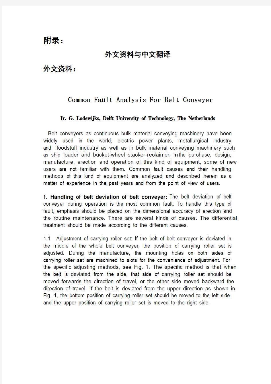
1.1Adjustment of carrying roller set: If the belt of belt conveyer is deviated in the middle of the whole belt conveyer, the position of carrying roller set is adjusted. During the manufacture, the mounting holes on both sides of carrying roller set are machined to slots for the convenience of adjustment. For the specific adjusting methods, see Fig. 1. The specific method is that when the belt is deviated from the side, that side of carrying roller set should be moved forwards the direction of travel, or the other side moved backward the direction of travel. If the belt is deviated from the upper direction as shown in Fig. 1, the bottom position of carrying roller set should be moved to the left side and the upper position of carrying roller set is moved to the right side.
1.2 Installation of self-aligning carrying roller set: There are many types of self-aligning carrying roller sets such as intermediate rotating shaft type, four-link type and edging roll type. The principle is that by utilizing blocking or rotating the rollers in the direction of horizontal plane, the rollers are blocked by rotating or the lateral thrust is produce to make the belt be automatically aligned so as to attain the object of adjustment of belt deviation. It is feasible, in general, to use this method when the whole length of belt of belt conveyer is shorter or the belt conveyer is operated in the bidirection. The causes are that the shorter belt conveyer is easier to be deviated and it is not easily adjusted. Therefore, this method is not used for the longer belt conveyers because use of self-aligning carrying roller sets can have certain influence on the service life of belt.
1.3 Adjustment of positions of head roll and bend pulley: Adjustment of head roll and bend pulley is a key link of adjustment of belt deviation. Since there are at least 2 to 5 pulleys in one belt conveyer, the mounting position of all the pulleys must be perpendicular to the central line along the length of belt conveyer. If the deviation is too large, the belt deviation occurs of necessity. The adjusting method is similar to that of carrying roller set. For head pulleys, if the belt is deviated from the right side of pulley, the bearing block at the right side should be moved forward and if the belt is deviated from the left side of pulley, the bearing block at the right side should be moved forward. For corresponding pulleys, the bearing block at the left side can be also moved backward or the bearing block at the right side moved backward. The adjusting method of tail pulleys is just opposite from that of head pulleys. For the adjusting method, see
Fig. 2. The pulleys are repeatedly adjusted till the belt is adjusted to the expected position. It is preferable to make the mounting position accurate before adjustment of head rolls or bend pulleys.
1.4 Adjustment of belt tensioning device: Adjustment of belt tensioning device is a very important link of adjustment of belt deviation of belt conveyer. Two bend pulleys on the top of counterweighted tensioning device should be not only perpendicular to the direction of the belt along length but also to the gravity vertical, i.e. it is ensured that the shaft center line is horizontal. When the screw tensioning device or hydraulic tensioning device is used, two bearing blocks of tensioning pulley should be synchronously translated so as to ensure that the axial line of pulley is perpendicular to the longitudinal direction of belt. The specific adjusting method of belt deviation is similar to the adjusting method of pulleys.
1.5 Influence of material receiving position at the transfer point on the belt deviation: The material receiving position at the transfer point has a great influence on the belt deviation, especially when the projection of two belt conveyers in the horizontal plane. The relative height of the upper belt conveyer and lower belt conveyer at the transfer point should be normally taken into consideration. The lower the relative height the greater the horizontal velocity component of material and also the greater the lateral impact on the lower layer of belt. In addition, the material is difficult to center so as to make the material at the cross section of belt be skew and finally lead to belt deviation. If the material is deviated from the right side, the belt will be deviated from the left side, vice versa. In the course of design, the relative height of two belt conveyers is increased as practically as possible. The form and dimension of the upper hopper and the lower hopper, chute etc. of bulk material mobile conveying machinery which are limited by space should be more carefully taken into consideration. In general, it is applicable for the width of chute being about 2/3 of that of belt. In order to reduce or avoid the belt from being deviated, the baffles can be increased to block the material and
change the falling direction and position of material. For the uncentering of material on the belt, see Fig. 3.
1.6 Adjustment of belt deviation of bi-directional belt conveyer: Adjustment of belt deviation of bi-directional belt conveyer is relatively more difficult than that of belt deviation of one-way belt conveyer. During the specific adjustment, the adjustment should be done from one direction, and then from the other. During adjusting, it must be carefully observed to the relationship between the travel direction of belt and the tendency of belt deviation. The adjustment should be done one by one. Firstly emphasis should be placed on adjustment of head rolls and bend pulleys. Secondly emphasis is placed on adjustment of the carrying rollers and the material receiving point. In addition, it should be noted that the load is uniformly distributed at the section of the belt along the length when the belt is at the vulcanized joints. When the leading chain is used for traction, the load at both sides should be distributed as equally as possible.
2. Material spillage on belt conveyer: Material spillage on the belt conveyer is a general character. The causes are embodied in several aspects. Therefore, emphasis is placed on strengthening the routine maintenance.
2.1 Material spillage at transfer point: Material spillage occurs mainly at the transfer points such as material receiving hopper and chute. If serious overload occurs on the belt conveyer, the rubber skirt plate of chute of belt conveyer can be damaged. Since the steel plate of chute is far from the rubber skirt plate in the design, the material will be flown out of the chute. The problem can be solved by controlling the conveying capacity and strengthening the routine maintenance.
2.2 Material spillage at the concave section of belt during hanging: The belt at the concave section is floated when the radius of curvature is smaller. At this tome the belt in the form of trough has been changed because the belt has been deviated from the trough carrying roller set. In that case, the angle of trough becomes small so as to make part of the material be split out. Therefore, the bigger radius of curvature at the concave section is used as practically as possible in the design in order to avoid the material spillage. If the concave section is designed according to the section of transition without arc in the mechanical traveling ship loader or stacker-reclaimer in order to shorten its tail car, the material spillage may easily occur when there is less room for selection of belt width.
2.3 Material spillage during the belt deviation: The material spillage occurs during the belt deviation because two edges of belt have changed in height during operation, i.e. one edge is higher and the other is lower. The material is split out from the lower edge. The handling method is to adjust the belt deviation.
3. Abnormal noise: When the belt conveyer is operated, it could sound abnormally from its drive, head roll, bend pulley or carrying roller set. The failure of equipment can be determined according to the abnormal noise.
3.1 Noise occurs when the carrying roller being seriously deviated: When the belt conveyer is operated, the abnormal noise could be produced and accompanied by periodic vibration, especially in the return rolls. The longer the roll and the heavier the deadweight, the higher the noise. There are mainly two causes for noise: one is that the wall thickness of seamless pipe made of carrying roller is non-uniform so as to produce the greater centrifugal force and the other is that during machining, the center of holes of bearing at both ends is greatly deviated from the center of top circle so as to produce the greater centrifugal force. The rolls can continue to use in case the bearings have not been damaged and the noise is allowed to exist.
3.2 Noise occurs when two shafts of coupling being not coaxial: The abnormal noise is produced from the coupling between the high-speed shaft of motor in the drive and that of reducer or from the coupling with brake wheel, it is also accompanied by the vibration that is identical with the rotational frequency of motor. If the noise is produced, the position of motor or reducer is adjusted in time in order to avoid the rupture of input shaft of reducer.
3.3 Abnormal noise of bend pulley and head roll: When the bend pulleys and head rolls are operated normally, the noise is very low. If the abnormal noise is produced, the bearing, in general, may be damaged. If the cackle is produced from the bearing block, the bearing must be replaced.
4. Rupture of shaft of reducer: The rupture of shaft of reducer generally occurs at the high-speed shaft of reducer. The usual fault is that the first-stage shaft of reducer is used as the high-speed shaft of vertical bevel gear shaft. There are mainly two causes for shaft rupture as follows.
4.1 Inadequate design strength of high-speed shaft of reducer: This fault, in general, occurs at the shaft shoulder. Because the transient round angle exists at this place, it is subjected to fatigue damage. If the round angle is too small, the rupture of shaft of reducer can occur in the short time. After shaft rupture, the fracture is generally flush. If this fault is found out, the reducer should be replaced or the design of reducer should be modified.
4.2 High-speed shaft being non-axial: When the high-speed shaft of motor is non-axial, the radial load will be increased on the input shaft of reducer so as to increase the bending moment on the shaft. If the shafts are operated in such a way for a long time, the shaft rupture could occur. During installation and maintenance, the position of shaft should be carefully adjusted in order to ensure that the two shafts are aligned. In most cases, the rupture of motor shaft can not occur, because the material used for motor shaft is #45 steel, the motor shaft is thicker and has good stress concentration.
4.3 Rupture of shaft in case two motors are used: The double-motor drive means that two reducers and two motors are installed on one head roll. When there is less room for design or selection of high-speed shaft of reducer, the shaft rupture easily occurs. In the past years the hydraulic coupling was not used in the drive of belt conveyer, so the failure easily occurred. The cause was that it was difficult to ensure that the speeds were synchronous and the loads uniformly distributed. Now the hydraulic couplings have been used in most of the belt conveyers, so the shaft rupture does not frequently occur, but it should be noted that the hydraulic coupling can not be filled with excess quantity of oil during operation so as to make it have an effect on limitation of moment of force and increase the service life of hydraulic coupling.
5. Shorter service life of belt: The service life of belt and the service modes are related to the quality of belt. It should be ensured that the cleaners are operated reliably and in good order when the belt is operated. There is not any material on the return belt. If the above can not be guaranteed, the material on the return belt will enters into the head roll or the bend pulley along with the return belt. The belt will be damaged due to the material on the surface of belt, resulting in damage of the vulcanized rubber layer on the surface of pulley, breach of the belt and decrease of the service life of belt. The manufacturing quality of belt is the problem the users relatively give attention to. After the selection of a model of belt, its manufacturing quality should be also taken into consideration. The belts can be inspected by the national specialized institution of quality determination. The appearance inspection is carried out conventionally to see whether the crazing and aging exist and the resting period is over long after manufacture. One of the above occurs, the belts should not be purchased. The fissured belt to be initially found will be, in general, damaged in a short time.
6. Influence of radius of curvature at the convex-concave section of belt on belt conveyer
6.1 Arch camber at the convex section of belt in the middle of cross section: The arch camber often occurs at the convex section in the middle of cross section and the belt will be pleated, see Fig. 4. After the overlapped
belt enters into the bend pulley or head roll, the extent of damage of belt aggravated. The main causes for arch camber and overlapping are that the difference between the values of tensile force in a unit of length at the cross section of belt in the middle and on the outside is oversized so that the belt is slid into the middle to form the arch camber or overlapping. The magnitude of difference value of tensile force in a unit of length is related to the radius of curvature at the convex section and the trough angle of carrying roller. The bigger the trough angle, the smaller the radius of curvature at the convex section and the severer the arch camber and overlapping. When the trough angle of belt conveyer is equal to and more than 40 degrees, the arch camber and overlapping can occur even at the transition section of trough angle of head or tail roll which is run at the straight section. At this time the trough angle should be reduced or the length of transition section increased so as to make the trough angle of belt be transited. For the belt conveyer at the convex section, the radius of curvature at the convex section should be increased as practically as possible and the trough angle of roll reduced in the condition that the conveying capacity is met.
6.2 The belt at the convex section being seized between flat roll and web roll: The belt being seized between the flat roll and the web roll in the carrying roller set may generally occur in the bulk material mobile
conveying machinery such as ship loader and stacker-reclaimer. The belt seizure may easily occur when the cantilever at the root position of cantilever
beam of such equipment is pitched downward. At this time it corresponds to the convex section occurring on the belt. The size required for the radius of curvature at the convex transition section can not be easily met because it is limited by the size of geometric position. The belt being seized between the flat roll and the web roll in the carrying roller set can occur only when the belt at the root of cantilever is passed through one or two carrying roller sets to form the convex section. The method of resolution is that the convex section formed by the original one or two carrying roller sets is changed to that formed by four or five carrying roller sets. For example, the belt conveyer is horizontally arrange at its rear, the cantilever is pitched downward at the angle of 12 degrees at its fore and the convex section is changed at the angle of 12 degrees. If five carrying roller sets are used to transit the angle change in this place, the belt is just buckled six times to attain the object of pitching downward at the angle of 12 degrees. The belt is buckled once at the angle of 2 degrees. After modification, the belt being seized between the flat roll and the web roll in the carrying roller set can not occur no longer. The design of four-link lever or follow-up frame can be used for the base of roller carrier in the transition place which position of angle is changed.
6.3 Bouncing and deflection of belt by the wind at the concave section when starting: If there is not any material on the belt when the belt conveyer is started, the belt will be bounced at the concave section and displaced by the wind in windy weather. Therefore, it is preferable that the pressure rollers are provided at the concave section to avoid the belt from being bounced or displaced by the wind.
7. Slipping of belt
7.1 Slipping of belt of belt conveyer with counterweighed tensioning device: When the belt is slid in the belt conveyer with counterweighted tensioning device, it can be solved by adding the balance weights till the belt can not be slid. However, the balance weights should not be excessive in order to avoid the belt from being subjected to unnecessary oversized tensile force, thus resulting in decrease of the service life of belt.
7.2 Slipping of belt of belt conveyer with screw tensioning device or hydraulic tensioning device: The tensioning travel can be adjusted to increase the tensile force when the belt is slid in the belt conveyer with screw tensioning device or hydraulic tensioning device. At this time, however, a section of the belt can be cut out for re sulfurzation when the tensioning travel is not enough or the belt is permanently deformed.
Brief summary:The belt conveyers are general-purpose mechanical equipment. They have been operated by the users for many years. However, the maintenance of belt conveyers must be done at regular intervals. Because
of limitation of the length of a piece of writing, it is difficult indeed to include all contents in one article. The experience with operation and maintenance of belt conveyer can be gradually accumulated through routine work. We hope that this text will be helpful for the users of belt conveyer.
中文翻译:
悬臂皮带输送机常见故障分析及处理
伊. 基. 劳德维加克斯,代尔夫特科技大学,荷兰
带式输送机作为连续散装物料的机械已广泛用于世界,发电厂,冶金工业,食品工业以及散装物料的输送,如装船机斗轮堆料机。在采购,设计,制造,安装和运行这种设备,一些新用户还不熟悉他们。从过去几年的经验和用户的观点和意见中,对这种设备常见故障原因和处理方法进行了分析和描述。
1皮带输送机皮带跑偏处理:在操作中,皮带输送机皮带跑偏是
常见的故障。为了解决这种类型的故障,重点应放在安装尺寸精度和日常维护。有几种原因,应根据不同原因区别对待。
1.1托辊的设置调整:如果皮带输送机皮带在输送机中间跑偏食,
需要对托辊的位置进行调整。在制造中,托辊上加工的双面安装孔是为了方便托辊的调整。对于具体的调整方法,见图1.具体的方法是,当带是从侧面偏离时,偏离一面的托辊运动方向应向前运动,而另一方面向后移动,如图1所示,如果皮带是向上跑偏,托辊底部位置设置应移动至左侧并且托辊上不移动至右侧。1.2自调心托辊的安装设置:自调心托辊的种类有许多,如:中间
转轴式,四连杆式和边辊式。其原理是在水平面内利用封锁或旋转的滚轮。滚轮式有旋转或产生横向推力使皮带自动对齐以达到对皮带跑偏的调整。这是可行的,在一般情况下,使用这种方法时皮带输送机皮带整体长度较短或皮带输送机是双向操作。其原理是较短的皮带输送机易跑偏并且不易调整。因此这种方法不用于较长的带式输送机,因为自调心托辊的使用对皮带的使用有一定的影响。1.3头部弯曲辊及滑轮的位置调整:调整头部弯曲辊及滑轮式对皮
带跑偏调整的关键环节。由于一个皮带输送机中至少有2到5个滑轮,所有滑轮的安装位置必须垂直于沿带式输送机长度中心线的方向。如果偏差过大,必然会发生跑偏。调整的方法类似于托辊组。对于头轮,如果从滑轮右侧跑偏,在右侧
的轴承座应当向前移动,如果带从滑轮左侧跑偏,在右侧的轴承座应当向前移动,对于相应的滑轮在左侧的轴承座也可以向后移动或在右侧的轴承座向后移动。尾部滑轮调整方法与头部相反。至于调整方法请参阅图2。滑轮反复调整直至皮带调整到预期位置。在调整头轮或弯曲滑轮前最好准确的安装。
1.4调整皮带涨紧装置:调整皮带涨紧装置是对皮带输送机皮带跑
偏调整的重要环节。在悬吊式配重张紧装置上不的两个弯曲滑轮不仅应垂直于沿皮带的长度方向并且应与重力方向相垂直,换言之,他是确保与轴中心水平。当螺旋张紧装置或液压张紧装置使用时,两个张紧轮轴承座应同步,以确保滑轮轴线垂直于皮带的纵向方向。具体的皮带跑偏调整方法类似于滑轮的调整方法。1.5物料的移交接收点对皮带偏差的影响:物料的移交接收点对皮
带跑偏的影响很大,尤其是两条皮带输送机的投影在同一水平面重合,上层输送带和下层输送带在移交点的相对高度,通常应认真考虑。相对高度越低,材料的水平分速度分量越大,对下层输送带的横向冲击越大。另外,物料的难以集中导致皮带的横截面倾斜,最终导致皮带跑偏。如果皮带从右侧偏离,皮带就向左偏离,反之亦然。在设计过程中,两个皮带输送机相对高度的增加实际上是可能的。上料斗和下料斗的结构和尺寸,散料输送机械都受到空间的限制,应更仔细的考虑。在一般情况下,它适用于约皮带宽度2/3的滑道。为了减少或避免皮带跑偏,挡板强度可增加到材料为块时的强度,改变物料下跌方向和材料位置。对于带上不确定的材料如图3.
1.6双向皮带输送机皮带跑偏的调整:双向带式输送机皮带跑偏的
调整相对于单向带式输送机更加困难。在具体的调整中调整应从一个方向,然后再调整下一个方向。调整过程中,必须仔细观察皮带行进方向和皮带跑偏趋势关系。调整应该一个接一个的完成。首先重点应放在调整头部托辊和弯曲滑轮。其次的重点是放在对托辊和材料的接受点。另外应指出的是,当皮带输送机硫化接头时,载荷应沿皮带长度方向均匀分布。当引导链牵引使用时,两面的载荷应尽可能的均匀分布。
2带式输送机的物料泄漏:物料泄漏在带式输送机上是一个普遍
现象。原因体现在几个方面。因此应放在加强日常维护。
2.1物料在转移点的溢出:物料泄漏主要发生在换乘点,如收料料斗,
溜槽。如果皮带输送机严重超载,橡胶皮带输送机溜槽就会受到损害。在设计时,如果钢板滑道远离橡胶板,该材料将会飞出溜班。这个问题可以通过控制输送能
摘要 带式输送机是输送能力最大的连续输送机械之一。其结构简单、运行平稳、运转可靠、能耗低、对环境污染小、便于集中控制和实现自动化、管理维护方便,在连续装载条件下可实现连续运输。本论文主要涉及了带式输送机的机械设计和电器原理设计部分。 带式输送机的机械设计程序分两步,第一步是初步设计,主要是通过理论上的计算选出合适的输送机部件。其中包括输送带的类型和带宽选择、带式输送机线路初步设计、托滚及其间距的选择、滚筒的选择、电动机、减速器、推杆制动器、液压软起动的选择等;第二步是施工设计,主要根据初步设计选定的滚筒、托滚、驱动装置完成对已选部件的安装与布置图纸设计工作。 最后,在机械设计的基础上,完成了对输送机的保护装置及其电器原理设计。电器控制主要通过可编程控制器实现(PLC)。 关键词:带式输送机;驱动装置;可编程控制器
Abstract Belt conveyor transmission capacity is one of the largest continuous transporting machine . Its structure is simple、smooth operation 、reliable functioning, and low consumption, little pollution, easy centralized control and automation And the continuous transportation of the facilities can be achieved in successive loading. The paper is mainly about the mechanical design and electrical principles belt conveyor design. There are two steps of designing the belt conveyor machinery. the first step is the preliminary design, mainly through theoretical calculations elected suitable carriers components. Including travel and the type of bandwidth selection, preliminary design belt conveyor lines, roll up their space options, roller choice, electric motors, reducer, push rod brakes, hydraulic soft start option; The second step is the construction design, based primarily on the preliminary design selected roller, roll up, driven devices have completed the installation of the components of the design and layout drawings. Finally, in the mechanical design basis for carriers I complete the design principles of the protection devices and appliances. the control of electrical equipment can be achieved primarily through programmable controller (PLC) . Keywords:belt conveyor;driven devices;programmable controller
带式输送机毕业设 计论文 目录 1 绪论 (1) 1.1常用带式输送机类型与特点 (2) 1.2 国外带式输送机的发展与现状 (3) 1.3 PLC简介 (8) 1.4 本课题的研究目的及选题背景 (12) 2 带式输送机初步设计 (13) 2.1 选择机型 (13) 2.2 输送带选择计算 (13) 2.3 输送线路的初步设计 (17) 2.4 托辊的选择计算 (18)
2.5 带式输送机线路阻力计算 (20) 2.6 输送带的力计算 (22) 2.7 输送带强度验算 (26) 2.8 牵引力及电动机功率的计算 (26) 2.9 驱动装置及其布置 (27) 2.10 拉紧力、拉紧行程的计算及拉紧装置的选择 (29) 2.11 制动力矩的计算及制动器的选择 (33) 2.12 减速器与联轴器的选型 (34) 2.13 软启动装置的选择 (35) 2.14 辅助装置 (36) 2.15设计结论表 (36) 3 带式输送机电控系统设计 (39) 3.1 电控系统的概述 (39) 3.2 电控系统设计基本要求 (40) 3.3 电控系统常用保护 (40) 3.4 电气系统设计 (41) 4 毕业设计总结 (49) 参考文献 (50)
致谢 (51) 附录一外文文献及翻译 (52) 附录二钢丝绳芯输送带规格及技术参数 (64)
1 绪论 带式输送机是一种摩擦驱动以连续方式运输物料的机械。应用它可以将物料在一定的输送线上,从最初的供料点到最终的卸料点间形成一种物料的输送流程。它既可以进行碎散物料的输送,也可以进行成件物品的输送。除进行纯粹的物料输送外,还可以与各工业企业生产流程中的工艺过程的要求相配合,形成有节奏的流水作业运输线。所以带式输送机广泛应用于现代化的各种工业企业中。在矿山的井下巷道、矿井地面运输系统、露天采矿场及选矿厂中,广泛应用带式输送机。它用于水平运输或倾斜运输,使用非常方便。带式输送机因其具有结构紧凑、传动效率高、噪声低、使用寿命长、运转稳定、工作可靠性和密封性好、占据空间小等特点,并能适应在各种恶劣工作环境下工作包括潮湿、泥泞、粉尘多等,所以它已经是国民经济中不可或缺的关键设备。加之国际互联网络化的实现,又大大缩短了带式输送机的设计、开发、制造的周期,使它更加具有竞争力。 研究本课题具有重要的意义。目前,带式输送机已经成为露天矿和地下矿的联合运输系统中重要的组成部分。为了更好的研究带式输送机的工作组成原理,发现及改进其不足之处,本课题所研究的是大倾角、上运带式输送机。此次研究的主要问题在于系统的驱动件布置、软起动和制动问题。带式输送机向下运送物料时,其驱动电机的运行工矿有别于一般的带式输送机。由于运转上的需要,在结构上有特点,控制上有特殊要求。若
中英文对照资料外文翻译文献 平设计任何时期平面设计可以参照一些艺术和专业学科侧重于视觉传达和介绍。采用多种方式相结合,创造和符号,图像和语句创建一个代表性的想法和信息。平面设计师可以使用印刷,视觉艺术和排版技术产生的最终结果。平面设计常常提到的进程,其中沟通是创造和产品设计。共同使用的平面设计包括杂志,广告,产品包装和网页设计。例如,可能包括产品包装的标志或其他艺术作品,举办文字和纯粹的设计元素,如形状和颜色统一件。组成的一个最重要的特点,尤其是平面设计在使用前现有材料或不同的元素。平面设计涵盖了人类历史上诸多领域,在此漫长的历史和在相对最近爆炸视觉传达中的第20和21世纪,人们有时是模糊的区别和重叠的广告艺术,平面设计和美术。毕竟,他们有着许多相同的内容,理论,原则,做法和语言,有时同样的客人或客户。广告艺术的最终目标是出售的商品和服务。在平面设计,“其实质是使以信息,形成以思想,言论和感觉的经验”。
在唐朝(618-906 )之间的第4和第7世纪的木块被切断打印纺织品和后重现佛典。阿藏印在868是已知最早的印刷书籍。在19世纪后期欧洲,尤其是在英国,平面设计开始以独立的运动从美术中分离出来。蒙德里安称为父亲的图形设计。他是一个很好的艺术家,但是他在现代广告中利用现代电网系统在广告、印刷和网络布局网格。于1849年,在大不列颠亨利科尔成为的主要力量之一在设计教育界,该国政府通告设计在杂志设计和制造的重要性。他组织了大型的展览作为庆祝现代工业技术和维多利亚式的设计。从1892年至1896年威廉?莫里斯凯尔姆斯科特出版社出版的书籍的一些最重要的平面设计产品和工艺美术运动,并提出了一个非常赚钱的商机就是出版伟大文本论的图书并以高价出售给富人。莫里斯证明了市场的存在使平面设计在他们自己拥有的权利,并帮助开拓者从生产和美术分离设计。这历史相对论是,然而,重要的,因为它为第一次重大的反应对于十九世纪的陈旧的平面设计。莫里斯的工作,以及与其他私营新闻运动,直接影响新艺术风格和间接负责20世纪初非专业性平面设计的事态发展。谁创造了最初的“平面设计”似乎存在争议。这被归因于英国的设计师和大学教授Richard Guyatt,但另一消息来源于20世纪初美国图书设计师William Addison Dwiggins。伦敦地铁的标志设计是爱德华约翰斯顿于1916年设计的一个经典的现代而且使用了系统字体设计。在20世纪20年代,苏联的建构主义应用于“智能生产”在不同领域的生产。个性化的运动艺术在2俄罗斯大革命是没有价值的,从而走向以创造物体的功利为目的。他们设计的建筑、剧院集、海报、面料、服装、家具、徽标、菜单等。J an Tschichold 在他的1928年书中编纂了新的现代印刷原则,他后来否认他在这本书的法西斯主义哲学主张,但它仍然是非常有影响力。Tschichold ,包豪斯印刷专家如赫伯特拜耳和拉斯洛莫霍伊一纳吉,和El Lissitzky 是平面设计之父都被我们今天所知。他们首创的生产技术和文体设备,主要用于整个二十世纪。随后的几年看到平面设计在现代风格获得广泛的接受和应用。第二次世界大战结束后,美国经济的建立更需要平面设计,主要是广告和包装等。移居国外的德国包豪斯设计学院于1937年到芝加哥带来了“大规模生产”极简到美国;引发野火的“现代”
运输机械讨论课 题目:通用带式输送机 国内外研究现状 1 国外带式输送机技术的现状国外带式输送机技术的发展很快,其主要表现在2个方面:一方面是带式输送机的功能多元化、应用范围扩大化,如高倾角带输送机、管状带式输送机、空间转弯带式输送机等各种机型;另一方面是带式输送机本身的技术与装备有了巨大的发展,尤其是长距离、大运量、高带速等大型带式输送机已成为发展的主要方向,其核心技术是开发应用于了带式输送机动态分析与监控技术,提高了带式输送机的运行性能和可靠性。目前,在煤矿井下使用的带式输送机已达到表1所示的主要技术指标,其关键技术与装备有以下几个特点:⑴设备大型化。其主要技术参数与装备均向着大型化发展,以满足年产300~500万t以上高产高效集约化生产的需要。 ⑵应用动态分析技术和机电一体化、计算机监控等高新技术,采用大功率软起动与自动张紧技术,对输送机进行动态监测与监控,大大地降低了输送带的动张力,设备运行性能好,运输效率高。⑶采用多机驱动与中间驱动及其功率平衡、输送机变向运行等技术,使输送机单机运行长度在理论上已有受限制,并确保了输送系统设备的通用性、互换性及其单元驱动的可靠性。 ⑷新型、高可靠性关键元部件技术。如包含CST等在内的各种先进的大功率驱动装置与调速装置、高寿命高速托辊、自清式滚筒装置、高
效贮带装置、快速自移机尾等。如英国FSW生产的FSW1200/(2~3)×400(600)工作面顺槽带式输送机就采用了液粘差速或变频调速装置,运输能力达3000 t/h以上,它的机尾与新型转载机(如美国久益公司生产的S500E)配套,可随工作面推移而自动快速自移、人工作业少,生产效率高。 国外带式输送机的主要技术指标国外300~500万t/a高产高效矿井主参数顺槽可伸缩带式输送机大巷与斜井固定式强力带式输送机运距/m 2000~3000 ﹥3000 带速/m.s-1 3.5~4 4~5,最高达8 输送量/t.h-1 2500~3000 3000~4000 驱动总功率/kW 1200~2000 1500~3000,最大达10100 2、国内带式输送机技术的现状我国生产制造的带式输送机的品种、类型较多。在“八五”期间,通过国家一条龙“日产万吨综采设备”项目的实施,带式输送机的技术水平有了很大提高,煤矿井下用大功率、长距离带式输送机的关键技术研究和新产吕开发都取得了很大的进步。如大倾角长距离带式输送机成套设备、高产高效工作面顺槽可伸缩带式输送机等均填补了国内空白,并对带式输送机的减低关键技术及其主要元部件进行了理论研究和产品开发,研制成功了多种软起动和制动装置以及以PLC为核心的可编程电控装置,驱动系统采用调速型液力偶合器和行星齿轮减速器。目前,我国煤矿井下用带式输送机的主要技术特征指标如下所示。国内带式输送机的主要指标 主参数顺槽可伸缩带式输送机大巷与斜井固定式强力带式输送机运距/m 2000~3000 ﹥3000 带速/m.s-1 3.5~4 4~5,最
江西理工大学应用科学学院10级(2014届) 学生毕业设计(论文)开题报告设计(论文)题目 专业学生姓名指导教师 本课题研 究的现状 十多年来,国产矿用固定式带式输送机从SDJ、SSJ、STJ、DT系列定型发展到各种多功能特种带式输送机系列,如大倾角带式输送机成套设备,高效工作面顺槽可伸缩带式输送机,大倾角长运距带式输送机系列产品等,并用动态分析、智能化控制技术等对关键设备进行了理论研究和产品开发,研制成功了多种软起动和制动装置以及可编程电控装置,但和国外先进机型相比,国内输送机机型一般较小,带速通常不超过4m/s,普遍沿用静设计法,设备成本偏高,运行可靠性低。此外我国尚未形成元部件的大规模专业生产厂,设计制造水平有待提高。 学术价值和现实意义 带式输送机因其具有结构紧凑、传动效率高、噪声低、使用寿命长、运转稳定、工作可靠性和密封性好、占据空间小等特点,并能适应各种恶劣工作环境下工作包括潮湿、泥泞、粉尘多等,所以它已经是国民经济中不可或缺的关键设备。加之国际互联网化的实现,有大大缩短了带式输送机的设计、开发、制造、销售的周期,使它更加具有竞争力。目前,带式输送机已经成为露天矿和地下矿联合运输系统中的重要组成部分。此次研究的主要问题在于系统的驱动件布置、软起动和制动问题。带式输送机向上运送物料时,其驱动电机的运动工况有别于一般带式输送机。由于运转上的需要,在结构特点上,控制上有特殊要求。上运带式输送机的制动装置及其控制技术尤为关键,若制动装置设计不合理,很容易发生飞车事故,从而造成断带、撕带等事故给生产带来极大危害,如何实现软制动和自动张紧,逐渐向智能化、自动化和人性化发展,是目前带式输送机的发展方向,也是本课题研究的目的和意义所在。
The development of plastic mould China's industrial plastic moulds from the start to now, after more than half a century, there has been great development, mold levels have been greatly enhanced. Mould has been at large can produce 48-inch big-screen color TV Molded Case injection mold, 6.5 kg capacity washing machine full of plastic molds, as well as the overall car bumpers and dashboards, and other plastic mould precision plastic molds, the camera is capable of producing plastic mould , multi-cavity mold small modulus gear and molding mold. --Such as Tianjin and Yantai days Electrical Co., Ltd Polaris IK Co. manufactured multi-cavity mold VCD and DVD gear, the gear production of such size precision plastic parts, coaxial, beating requirements have reached a similar foreign the level of product, but also the application of the latest gear design software to correct contraction as a result of the molding profile error to the standard involute requirements. Production can only 0.08 mm thickness of a two-cavity mold and the air Cup difficulty of plastic doors and windows out of high modulus, and so on. Model cavity injection molding manufacturing accuracy of 0.02 to 0.05 mm, surface roughness Ra0.2 μ m, mold quality, and significantly increase life expectancy, non-hardening steel mould life up to 10~ 30 million, hardening steel form up to 50 ~ 10 million times, shorten the delivery time than before, but still higher than abroad,and the gap between a specific data table. Process, the multi-material plastic molding die, efficient multicolor injection mould, inserts exchange structure and core pulling Stripping the innovative design has also made great progress. Gas-assisted injection molding, the use of more mature technologies, such as Qingdao Hisense Co., Ltd., Tianjin factory communications and broadcasting companies, such as mold manufacturers succeeded in 29 ~ 34-inch TV thick-walled shell, as well as some parts on the use of gas-assisted mould technology Some manufacturers also use the C-MOLD gas-assisted software and achieved better results. Prescott, such as Shanghai, such as the new company will provide users with gas-assisted molding equipment and technology. Began promoting hot runner mold, and some plants use rate of more than 20 percent, the general heat-thermal hot runner, or device, a small number of units with the world's advanced level of rigorous hot runner-needle device, a small number of units with World advanced level of rigorous needle-hot runner mould. However, the use of hot runner overall rate of less than 10%, with overseas compared to 50 ~ 80%, the gap larger. In the manufacturing technology, CAD / CAM / CAE technology on the level of application of a new level to the enterprise for the production of household appliances representatives have introduced a considerable number of CAD / CAM systems, such as the United States EDS UG Ⅱ,
国外带式输送机技术的现状国外带式输送机技术的发展很快,其主要表现在2个方面:一方面是带式输送机的功能多元化、应用范围扩大化,如高倾角带输送机、管状带式输送机、空间转弯带式输送机等各种机型;另一方面是带式输送机本身的技术与装备有了巨大的发展,尤其是长距离、大运量、高带速等大型带式输送机已成为发展的主要方向,其核心技术是开发应用于了带式输送机动态分析与监控技术,提高了带式输送机的运行性能和可靠性。目前,在煤矿井下使用的带式输送机其关键技术与装备有以下几个特点: ⑴设备大型化。其主要技术参数与装备均向着大型化发展,以满足年产300~500万t以上高产高效集约化生产的需要。 ⑵应用动态分析技术和机电一体化、计算机监控等高新技术,采用大功率软起动与自动张紧技术,对输送机进行动态监测与监控,大大地降低了输送带的动张力,设备运行性能好,运输效率高。 ⑶采用多机驱动与中间驱动及其功率平衡、输送机变向运行等技术,使输送机单机运行长度在理论上已有受限制,并确保了输送系统设备的通用性、互换性及其单元驱动的可靠性。 ⑷新型、高可靠性关键元部件技术。如包含CST等在内的各种先进的大功率驱动装置与调速装置、高寿命高速托辊、自清式滚筒装置、高效贮带装置、快速自移机尾等。如英国FSW生产的FSW1200/(2~3)×400(600)工作面顺槽带式输送机就采用了液粘差速或变频调速装置,运输能力达3000 t/h以上,它的机尾与新型转载机(如美国久益公司生产的S500E)配套,可随工作面推移而自动快速自移、人工作业少、生产效率高。 表1国外带式输送机的主要技术指标 目前,国外已有多家工程设计公司致力于带式输送机设计系统的研究,并开发出各具特色的满足不同应用要求的设计系统。如美国 CDI 公司主要从事带式输送机的设计和咨询工作,在国际输送机设计领域处于领先地位,主要业务范围包括机械设计、水平曲线设计、动态分析和控制系统设计、设备调试及试运行等等;澳大利亚的 Helix Technologies Pty Ltd 专门从事工程软件开发,已开发出一系列工程管理、投资分析的软件系统,如输送机设计、管道网络分析、泵的选型和 V 型输送带/链的驱动设计等。
Abstract: A supporting body of diatomite-based porous ceramics was prepared by a solid-phase sintering process and low-temperature calcination process. A nano-TiO2 compound membrane was loaded on the supporting body by the hydrolysis precipitation method and using TiCl4 as the forerunner body, and the TiO2/diatomite-based porous ceramic composite structure was characterized by X-ray diffraction and scanning electron microscopy and so on. The photocatalytic activities of TiO2 films were investigated by the degradation of formaldehyde. The results indicate that the TiO2 films in TiO2/diatomite-based porous ceramic composite calcined at 550 ℃are anatase, and the average grain size of TiO2 is 10.9 nm. The elimination rate of the composites for formaldehyde reaches 96.8% in 6 h under an ultraviolet lamp irradiation of 8 W, and the concentration of formaldehyde drops to 0.015 mg/m3 from 0.463 mg/m3. Key words: diatomite-based porous ceramics; nano-titania compound membrane; water solution precipitation method; formaldehyde; photocatalytic activity 摘要:采用固相烧结法和低温煅烧工艺,制备了硅藻土基多孔陶瓷支承体。以四氯化钛为前驱体,采用水解沉淀法在支承体上负载纳米TiO2复合膜。用X射线衍射仪和扫描电子显微镜等对TiO2复合膜/多孔陶瓷支承体的复合结构进行了表征;并以甲醛为降解对象,考察了TiO2复合膜的光催化性能。结果表明:纳米TiO2/硅藻土基多孔陶瓷复合膜在550℃煅烧后TiO2为锐钛矿型,平均晶粒粒径为10.9 nm。在紫外光照射240min后,甲醛气体初始浓度由0.463 mg/m3 降至0.015 mg /m3,复合材料对甲醛的去除率达到96.8%。 关键词:硅藻土基多孔陶瓷;纳米二氧化钛复合膜; 水解沉淀法;甲醛;光催化性能Abstrac:t Photocatalytic ceramic foam filter, the composite of high photo active TiO2 nano mate rials and three dimensional porous ceramic foam materials, has been widely applied in the field of air /water purification, owing to its characteristics of high photoactivity, large surface area, large flowing flux and ceramic heat/ chemical resistance, recycling probability. Applications have been in the fields of industrial exhaust deodorization, agriculture pesticide degradation using sunlight, sterilization of laboratories and hospitals, high-speed train air purification, and so on. The application research progress, problem and future prospect of photo catalytic ceramic foam filter are summarized. Key words: photo catalyst; ceramic foam filter; application; air /water purification 摘要: 高活性的光催化二氧化钛纳米材料与高气孔率的三维多孔泡沫陶瓷材料复合, 得到的光催化泡沫陶瓷过滤器, 具备高活性、大表面积、大通量、以及陶瓷的耐高温、耐化学腐蚀、循环适用性, 在大气/水净化领域率先得到了广泛应用。在工业领域的废气脱臭处理、在农业领域的农药废水太阳光降解、在医疗卫生领域的实验室医院空气杀菌处理、在交通领域的高速列车空气净化等, 已经展开应用。综述了国内外光催化泡沫陶瓷过滤器的应用研究现状、问题及其发展趋势。 关键词: 光催化; 泡沫陶瓷过滤器; 应用研究; 大气/水净化
摘要 本次毕业设计是关于DTⅡ型固定式带式输送机的设计。首先对胶带输送机作了简单的概述;接着分析了胶带输送机的选型原则及计算方法;然后根据这些设计准则与计算选型方法按照给定参数要求进行选型设计;接着对所选择的输送机各主要零部件进行了校核。普通型带式输送机由六个主要部件组成:传动装置,机尾或导回装置,中部机架,拉紧装置以及胶带。最后简单的说明了输送机的安装与维护。目前,胶带输送机正朝着长距离,高速度,低摩擦的方向发展,近年来出现的气垫式胶带输送机就是其中的一个。在胶带输送机的设计、制造以及应用方面,目前我国与国外先进水平相比仍有较大差距,国内在设计制造带式输送机过程中存在着很多不足。 本次带式输送机设计代表了设计的一般过程, 对今后的选型设计工作有一定的参考价值。 关键词:带式输送机传动装置导回装置
Abstract The design is a graduation project about the belt conveyor. At first, it is introduction about the belt conveyor. Next, it is the principles about choose component parts of belt conveyor. After that the belt conveyor abase on the principle is designed. Then, it is checking computations about main component parts. The ordinary belt conveyor consists of six main parts: Drive Unit, Jib or Delivery End, Tail Ender Return End. Intermediate Structure, Loop Take-Up and Belt. At last, it is explanation about fix and safeguard of the belt conveyor. Today, long distance, high speed, low friction is the direction of belt conveyor’s development. Air cushion belt conveyor is one of them. At present, we still fall far short of abroad advanced technology in design, manufacture and using. There are a lot of wastes in the design of belt conveyor. Keywords: the belt conveyor Drive Unit Delivery End
Building materials Building materials must have certain structural use.it physical properties. First, they must be able to bear load or weight without permanent deformation. When the load on the structural components, components will deformation, it means rope will be stretching or beam will bend. However, when the load is removed, ropes and beams will return to its original position. This kind of material properties is called elasticity. If material is not elastic, then on removing load deformation exist, repeat the loading and unloading eventually increase deformation to structural lose action. All used in building structure in the materials such as stone, brick, wood, aluminum, reinforced concrete and plastic within a certain range of load performance of flexibility. If loading beyond the scope, two things will happen: brittle and plastic. If it is the former, the material will suddenly destruction; If the latter, in certain load (yield strength) material has begun to yield flow, resulting in destruction. For example, steel, stone material is brittle present plastic. Materials by the damage occurred when the ultimate strength of stress decision. Construction materials and an important characteristic is its stiffness. This feature by elastic modulus decision. Stress (per unit of area, the force) and the strain (per unit length ratio of the deformation) is elastic modulus. Elastic modulus is characterize material under load shape-shifting abilities. For two have the same area and load of the same material. Elastic modulus big materials little deformation. Structure with steel of elastic modulus is pounds per square inch or kg per square centimeter, aluminum, concrete 3 times of ten times, wood 15 times. Masonry. Masonry from natural materials such as stone and artificial materials such as brick, concrete blocks composed. Masonry in ancient times is used. Bricks used in city of Babylon not religious buildings, stone material used in large temples of the Nile valley. The pyramids of Egypt, high 481 feet (147m), is the most spectacular masonry structure. Masonry unit initial without using any binding materials piled up, and modern masonry structure as binder materials. Water mud Modern structure material including stone, red-roast clay brick or tiles, the concrete blocks.
《基于PLC的矿用皮带运输的控制系统》文 献综述 容摘要 皮带运输机是一种有牵引件的连续运输设备,广泛应用于矿产开采、金属冶炼、化工、铸造等行业的生产线和输送线以及港口的生产部门。主要用来运送物料,根据输送工艺的要求,可以单台输送,也可以多台组合输送,或者和其它输送设备组成水平或倾斜的输送系统。煤矿的输送系统对保证矿井正常生产起着极其重要的作用。本设计主要叙述了利用先进的PLC技术对煤矿企业皮带机系统进行技术改造方案,并且叙述了皮带机的基本原理、皮带机集中控制系统设计步骤。 PLC是一种专门在工业环境下应用而设计的数字运算操作的电子设备。它采用可编程存储器,用来在其部存储执行逻辑运算、顺序运算、计时、计数和算数运算等操作的指令,并能在其部存储进行数字或模拟式的输入和输出,控制各种类型的机械或生产过程。 关键词:煤矿;皮带运输机;集中控制系统;PLC
国外皮带运输机的研究现状 国外在皮带运输机动态分析研究方面发展的比较早,动态分析理论与研制的软件已经基本能够满足当前的发展需求;而我国则比较晚,跟国外相比,还存在比较大的差距,尤其是动态分析的软件部分。为了尽快弥补差距,赶超世界先进水平,有必要研究跟分析当今国外皮带运输机的动态分析软件。目前,美国、法国意大利等发达国家在动态分析研究方面,已经达到了国际领先地位。我国生产制造的上运式带式输送机的种类较多。在“八五”时期,通过国家一条龙“日产万吨综采设备”项目实施,皮带运输机的技术水平有了很大的提高,煤矿井下用大功率、长距离带式输送机的关键技术研究和新产品开发都取得了很大的进步。如大倾角、长距离带式输送机成套设备、高产高效工作面顺槽可伸缩带式输送机等都填补了国空白,并对带式输送机的主要元部件进行了理论研究跟产品的开发,研制成功了多种软启动和制动装置以及以PLC为核心的可编程电控装置,驱动系统采用可调速型液力耦合器和行星齿轮减速器。
页眉内容 济南大学泉城学院 毕业设计方案 题目带式输送机的设计 专业机械设计制造及其自动化 班级机设10Q4 学生董吉蒙 学号012 指导教师顾英妮 二〇一四年三月二十一日
学院泉城学院专业机械设计制造及其自动化 学生董吉蒙学号012 设计题目带式输送机的设计 一、选题背景与意义 随着工业化经济的不断增长,带式输送机作为输送行业中的重要设备,其技术发展已成为输送设备发展更替的重要标志之一。全球化经济的发展和提倡低能环保机械的倡导,设计出低能耗和环保新型带式输送机又成为众多工程技术人员的目标。 目前带式输送机的发展趋势主要集中在长距离、高速度、大运量、大功率等方向,其特点将得到充分的发挥,更具有现代物流发展意义,与传统的直线输送机搭接、汽车等其它运输工具相比具有明显的优点。 生产实践证明,带式输送机与其他运输机械相比,其相关技术指标都表现出明显的优越性,但作为机械设备来讲,都会有自身的不足之处,如通用带式输送机的运动零部件多,维护维修费用大问题、由于托辅的原因带速受限问题,再比如输送机的起动、输送带的振动易跑偏和摩擦起热等问题,近些年来,国内外研究机构对诸如此类的问题都做了大量的研究,相关的科学技术研究取得了重要的突破。 国内研究现状 尽管我国已拥有先进的软起动技术及多机功率平衡技术、中间驱动技术,而且掌握的技术完全可满足煤矿长距离带式输送机的需要,但由于国内输送带技术跟不上国外先进国家,带强受到限制,无法满足高强度带式输送机发展的需要。因此,输送机驱动系统必须尽量减少对输送机各部件的动负荷,控制对输送带的动张力,防止输送带在滚筒上的打滑,减小张紧行程。因此,输送机的起制动要求更高,据有关资料介绍,上运输送机最佳的起动特性曲线应为“S”形,有必要进一步研制新型启动技术和自动张紧技术。 国外研究现状 国外对于无辑式特种带式输送机的研究较早,成果也相对丰富。气垫式带式输送机最初始于荷兰,系统介绍气垫式带式输送机的文献出自荷兰TWERTE大学,一种供运送旅客用的气垫输送机取得专利,另外国外还有供搬集装箱的新型双气垫输送机。国外有关气塾带式输送机的专利有几十项,国外主要的生产厂家有,荷兰的Shiis公司,英国的Simon-Carves和Numec公司等,在初期阶段,国外的气垫带式输送机多用于输送面粉、谷物等密度较小的散状物料,近些年来,幵始用于输送憐酸盐、煤矿等密度较大且刚性大的物料,并逐渐向长距离、高运速和大运量上发展。 - 1 -
. . XX大学XXXXXXX 外文资料和译文 专业:软件工程 班级:软件XXXXX 姓名:XXXXX 学号:XXXXXXXXXXXXXX 指导教师:XXXXXXXX 2009 年 12 月 17 日
原文 1.1 A JSP technology overview Let's begin by talking a little about how JSP pages work. We're going to keep it simple and focus on some of the basics. For more information, see Resources for links to additional JSP technology information. In the traditional sense, JSP pages look very much like HTML pages, with a few extra tags. These tags allow the designer to embed Java code (not JavaScript) in the page itself. A Web application server, like the IBM WebSphere Application Server, will intercept requests for JSP pages. It's tipped off to their existence by the page's extension: .jsp (not .html). The Web application server then preprocesses the JSP page, taking out the JSP tags and any embedded Java code, leaving only the HTML. The extracted JSP tags and embedded Java code are used to build a Java servlet (JSP page servlet) that runs the code and inserts the results back into the original page where the JSP tags used to be. The result is pure HTML. The Java is stripped out and run on the server before the requesting browser sees any result. We can apply the same principle to an XML page. Before the requester of the JSP page containing XML ever sees the XML (be it a browser or some other B2B application), the Java code is stripped out of the JSP page and used to generate additional content, which is inserted back into the page at the points where the JSP tags used to reside. This feature gives you the ability to control exactly where new content is to be inserted, down to the character. We'll look at how to make this work in a minute. First, let's consider why you might want to create dynamic XML using JSP. Why not simply write a Java application or servlet to generate the entire document? Why bother with JSP at all? The most important reason, providing only portions of an XML document are dynamic, is that it makes sense not to regenerate that