Trans. Nonferrous Met. Soc. China 24(2014) 441?
448
A gradient nano/micro-structured surface layer on copper induced by
severe plasticity roller burnishing
Jing ZHAO, Wei XIA, Ning LI, Feng-lei LI
National Engineering Research Center of Near-net-shape Forming Technology for Metallic Materials,
South China University of Technology, Guangzhou 510640, China
Received 28 January 2013; accepted 12 September 2013
Abstract: In order to investigate a gradient nano/micro-structured surface layer on pure copper produced by severe plasticity roller burnishing (SPRB) and grain refinement mechanism, the microstructure characteristics and material properties of sample at various depths from the topmost surface were investigated by SEM, TEM, XRD, OM etc. The experimental results show that the gradient nano/micro-structure was introduced into the surface layer of over 100 μm in thickness. The remarkable increase in hardness near the topmost surface was mainly attributed to the reduced grain size. The equiaxed nano-sized grains were in random orientation and the most of their boundaries were low-angle grain boundaries (LAGBs). The coarse grains are refined into the few micro-sized grains by dislocation activities; deformation twinning was found to be the primary form for the formation of submicron grains; the formation of nanostructure was dominated by dislocation activities accompanied with rotation of grains in local region. Key words: burnishing; pure copper; gradient nano/micro-structure; surface nanocrystallization
1 Introduction Owing to the extraordinary mechanical and physical properties of surface nanocrystallization (SNC) materials [1,2], numerous SNC techniques have been proposed. Among these techniques, surface self-nanocrystallization (SSNC) techniques gradually attract great interests of researchers since they can utilize the traditional surface processing techniques to fabricate SNC materials without considering the adhesion force between the nanocrystalline surface layer and matrix [3]. Most SSNC techniques rely on multidirectional or monotonic high-speed impact on the sample surface to refine coarse grains into nano-sized grains, such as surface mechanical attrition treatment (SMAT) [4?6], high energy shot peening (HESP) [7], ultrasonic shot peening (USSP) [8], ultrasonic surface processing (USER) [9]. Nevertheless, the poor surface qualities of the treated surface layer hinder the extensive industrial application. It is worth noting that LU et al [10] have synthesized a gradient nano/micro-structure in the surface layer on copper, by the surface mechanical grinding treatment (SMGT) in recent years. The treated nano-sized copper would
become an ideal engineering material because of its high strength and good tensile plasticity [11]. However, the
usage of liquid nitrogen cooling to avoid grain recovery and/or recrystallization is not suitable for industrial production. In short, difficulty in finding an easy-implementation and low-cost SSNC technique is a main obstacle for industrial application and development of SNC metals and alloys. Burnishing, similar with SMGT, has a processing way of repetitive extrusion on material surface, which makes it possible to fabricate the gradient nano/micro- structured surface layer. In fact, recent investigation has demonstrated that Mg alloy with a gradient ultrafine- grain surface layer was produced using cryogenic burnishing [12]. In our work, a new SSNC technique based on burnishing is proposed, named severe plasticity roller burnishing (SPRB), which has produced a gradient nano/micro-structure on copper successfully at room temperature. This newly developed technique has a promising prospect in industrial application than SMGT since it achieved the gradient nano/micro-structured surface layer only by an ordinary lathe and a simple
Foundation item: Project (50975095) supported by the National Natural Science Foundation of China; Project (2012ZM0048) supported by the
Fundamental Research Funds for the Central Universities, China
Corresponding author: Jing ZHAO; Tel: +86-20-87112948-303; E-mail: zhjing.zh@https://www.doczj.com/doc/0d17646561.html, DOI: 10.1016/S1003-6326(14)63080-6
Jing ZHAO, et al/Trans. Nonferrous Met. Soc. China 24(2014) 441?448 442
burnishing tool. The microstructural evolution
mechanism and the formation of gradient nano/micro- structure involved in SPRB are essential and crucial issues to help us to understand the properties of SNC material induced by SPRB more comprehensively.
The strain-induced microstructure evolution and the refinement mechanism of SSNC process have been of great concern in the past decades. The diversity of the plastic deformation mode caused by various techniques and materials affects the behavior and microstructural evolution of nanostructured materials [3]. So the obvious difference in plastic deformation mode between impact- typed SSNC and extrusion-typed SSNC definitely causes the distinction on deformation mechanism and microstructure characteristics. For example, the fibrous structure in the plastic deformation layer is not seen in SMAT [5], but is common seen in SMGT [10]. However, most investigations on deformation mechanism of SSNC processes are based on the impact-typed SSNC techniques, but little work has been reported on the mechanism underlying the grain refinement of the extrusion-typed ones up to now.
The objective of the present work is to study the grain refinement mechanism involved in SPRB by the microstructure features of gradient nano/micro- structured surface layer on copper at different depths from the top surface. The surface performance improvement of the deformation layer including surface roughness and hardness is also our concern.
2 Experimental
A rod sample with dimensions of d40 mm×10 mm was attained from a pure copper (99.97% in mass fraction) bar for SPRB. The initial grain size of the sample was about 75 μm. In order to increase the pressure induced by burnishing tool, a boss (1 mm in width and 6 mm in height) was machined on the end face of the sample at a feed rate of 0.12 mm/r and a spindle speed of 560 r/min under oil lubrication (SAE10W?30).
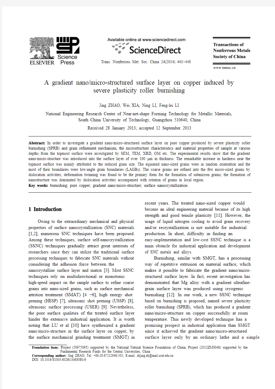
Figure 1(a) gives the experimental set-up of SPRB. The process was conducted on a C6132A1 lathe. A designed tool with 5 equally distributed rollers (d6 mm×8 mm), made of YG-8 cemented carbide, was used. An S-type pressure sensor was connected with the lathe to obtain the real-time radial burnishing force (F r). The sensor signal was acquired through the Advantech USB?4711A DAQ card and processed on PC. Before SPRB, the burnishing tool was clamped on the lathe tailstock and applied a given preload on the boss. When the SPRB began, the roller rotated at a high speed to decrease the height of boss rapidly, as shown in Fig. 1(b). The process was time-controlled with the duration of 90 s per pass. The process was conducted at a spindle
Fig. 1 Experimental set-up: (a) Site set-up; (b) Schematic of SPRB (Inset gives TD, ND in sample reference system)
speed of 560 r/min and a burnishing load of 2100 N 8 passes under oil lubrication (SAE10W?30) at room temperature. The height of boss was finally reduced to ~1 mm. The stain rate was estimated at 102?103 s?1 in the top surface layer of the sample [13].
The sample was polished with carbide papers to the specified depths, measured by displacement sensor OD5-25W01 at a resolution of 0.02 μm. The microstructural evolution at different depths was characterized by an optical microscope (OM, Leica DM1500) and scanning electron microscope (SEM, Nano 430). The top surface of sample was investigated by a transmission electron microscope (TEM, JEOL 3010). The X-ray diffraction (XRD, Rigaku D/max 2500PC X-ray diffractometer) measurement was carried out at 40 kV and 150 mA using Cu Kα radiation on the RD?TD plane of sample, as shown in Fig. 1(b). The surface roughness improvements of the sample were measured by a BMT Expert 3D measurement system. The microhardness at each depth was determined by a HVS?1000 Vickers hardness testing machine, with a load of 4.9 N and a loading time of 20 s. The mean value was determined from the values around a mark point. The grain size distribution was a statistical result of 200 grains selected randomly from Fig. 5. A pair of
Jing ZHAO, et al/Trans. Nonferrous Met. Soc. China 24(2014) 441?448 443
orthogonal lines were drawn through the long axis and short axis of a grain. The pixel lengths of long axis and short axis were read and converted into the real lengths.
3 Results
3.1 Microstructure
3.1.1 Cross-sectional observations
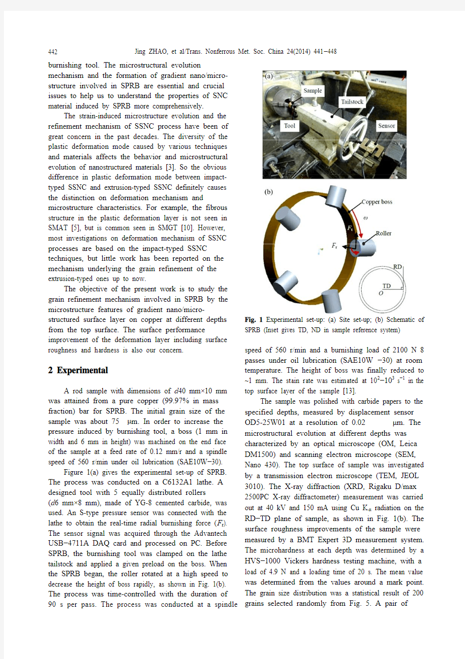
The cross-sectional SEM observation of the sample
is shown in Fig. 2. It can be seen that a gradient structure forms in the surface layer, representing the strain decrease from the maximum at the topmost surface to zero in the matrix. The grain boundaries of the top layer (depth<100 μm) could hardly be identified, which indicates that severe plastic deformation occurs in the top layer during SPRB. It is worth mentioning that the gradient structure is similar with the one observed after SMGT [10], but is more uniform compared with latter at the same depth. The thickness of the deformation layer is about 600 μm, which is twice that by SMAT for 5 min [5].
Fig. 2 SEM image showing cross-section of sample
In order to investigate the grain refinement process involved in SPRB, microstructure characterizations of sample at different depths from the topmost surface, marked by h0?h6 in Fig. 2, were conducted.
3.1.2 Microstructure characteristics of deformation layer
Figure 3(a) shows that the grains at h6 have no obvious deformation, and the grain boundaries are straight, which can be defined as the matrix. With increasing the deformation strain at h5, as shown in Fig. 3(b), the grains are elongated slightly and some grain boundaries are blurred and curved. At h4, fiber structures form along burnishing direction, leading to the segmentation of coarse grains. The refinement degree of the coarse grains is significantly different. The grain refinement in some regions is faster than other regions. For example, equiaxed grains with size of ~5 μm marked with arrows in Fig. 3(c), are quite smaller than ones in other regions.
It is well recognized that the degree of etch is same for the same lattice plane of a material, so we define two types of regions in Figs. 3(d)?(f): bright (a region labeled with ‘B’ in Fig. 3(d)) and dark (a region labeled with ‘D’ in Fig. 3(d)) regions, to reveal the evolutions of microstructure and grain orientation. The grains in dark regions are smaller than the ones in bright regions (Fig. 3(d)), indicating that the dark regions are of newly generated fine-grained structure. The grain orientations of dark regions are approximate with those of the preferential refinement regions in Fig. 3(c). It can be observed that the total area ratio of the dark regions to the bright ones increases with decreasing the depths from the top surface (Figs. 3(e)?3(f)). These findings indicate clearly that the dark regions play an important role in the grain refinement.
It can be concluded that the grain orientations of dark regions are preferential at h1 from Fig. 3(f). Texture analysis gives more details of grain orientation to reveal the formation of submicron grains. The deformation textures were determined from the (200), (220), (111) and (311) pole figures. The experimental data were processed to obtain the orientation distribution function f(g) (ODF). The φ2=0, 45° sections of ODF for the samples before and after SPRB are shown in Fig. 4. The XRD measured depth is about 30 μm from the topmost surface of sample. The textures before SPRB consist of components like {001}?110? rotated cube (RC), {110}?001? Goss (G), {110}?110? rotated Goss (RG) and {114}?221? (G T), which is the ideal twin orientation of goss. The ODF of the burnished sample shows an orientation density increase around the RG component while other components existing before SPRB almost disappear. The strength of {114}?110? (RG T), the ideal twin orientation of the rotated Goss, is roughly equal to that of RG component after SPRB.
SPRB can be simplified in the form of tension along TD and compression along ND, so the Schmid factor m can be expressed as [14]
cos cos cos cos
mαβγδ
=?(1) where α is the angle between TD direction and slip/twin direction; β is the angle between TD direction and the normal of slip/twin plane; γis the angle between ND direction and slip/twin direction; δ is the angle between ND direction and the normal of slip/twin plane. According to Eq. (1), the Schmid factors (SF) for slip/twin systems of the components existing before and after SPRB are calculated. The maximum Schmid factors for slip/twin systems and the corresponding number of active slip/twin systems having the maximum SF are listed in Table 1.
Jing ZHAO, et al/Trans. Nonferrous Met. Soc. China 24(2014) 441?448
444
Fig. 3 OM images showing microstructures of sample at different depths from topmost surface: (a) h6=600 μm; (b) h5= 300 μm;
(c) h4=200 μm; (d) h3=100 μm; (e) h2=60 μm; (f) h1= 30 μm
Fig. 4 ODF representing textures of samples before SPRB (I max=2.4; level=0.45, 0.46, 1.00, 1.30, 1.60, 1.80, 2.10) and after SPRB(I max=4.8; level=0.00, 1.00, 1.80, 2.50, 3.30, 4.00): (a) φ2=0, before SPRB; (b) φ2=45°, before SPRB; (c) φ2=0, after SPRB; (d) φ2=45°, after SPRB Table 1 The maximum Schmid factors M max for slip systems
and twin systems and corresponding numbers of active slip systems and twin systems during SPRB
Slip system Twin system Texture
component Number M
max
Number M max RG 4 0.82 2 0.94 RC 4 0.82 2 0.94 RG T 2 0.82 1 0.94 Larger SF of component means that the grain with this orientation is easier to deform, which can promote
the grain refinement. The RG, RG T and RC have the largest SF for twin systems shown in Table 1, which is consistent with the texture results of the burnished sample. Assume that the critical resolved shear stress for
slip is equal to that for twinning. The results show the onset of twinning is easier than dislocation slip for the
Jing ZHAO, et al/Trans. Nonferrous Met. Soc. China 24(2014) 441?448 445 three components. The twinning relation between RG
and RG T indicates that part of RG T component evolves from RG component. Meanwhile, the strength values of two components are almost the same. It can be concluded that most grains are in the form of twins. Besides, the Schmid factors for slip systems of these three components are also high, which means that the dislocation slipping is also activated and works together with the twinning in microstructural evolution. It should be noticed that XRD has a certain penetration depth for a given material. The penetration depth of copper is verified as 19 μm by Beer–Lambert law, so the texture measured is an average value in the range of 30?50 μm depth from the topmost surface.
In the top surface, the microstructure is characterized by nano-sized grains from TEM observations (Fig. 5). The corresponding selected-area electron diffraction (SAED) pattern shown in Fig. 5 indicates that randomly oriented grains are obtained by SPRB. The grain size distributions of long axis and short axis confirm to the normal logarithmic distribution approximately (Fig. 6). The average long axis grain size (d l) and short axis grain size (d s) are 11 and 8 nm respectively. So the nano-sized grains can be fairly considered being equiaxed with the (d l/d s) of 1.2.
Fig. 5 Bright field image of top surface of burnished copper
3.1.3 Region definition of gradient nano/micro-
structured surface layer
The grain size distributions at h0?h3 are shown in Fig. 7. The error bars for the arithmetic mean that values of grain sizes are calculated. The arithmetic mean values of grain size get smaller when the depth is close to the topmost surface, which indicates that the grain refinement is more uniform in the top surface. The grain size of short axis at h1 is partly in the nanometer range, so the SNC layer is defined as 0?30 μm. The average size of short axis at h3 is out of 1000 nm, so the sub-micron layer is defined as 30?100 μm. In short, the thickness of the gradient nano/micro-structured surface layer is about 100 μm from the topmost surface, which is much larger than that in Ref. [15].
Fig. 6 Grain size distributions of long axis (d l) (a) and short axis (d s) (b) in top surface (Inset gives the ratio of d l/d s)
Fig. 7 Grain size distributions at h0, h1, h2, h3 and corresponding hardness values
3.2 Improvement on surface properties of
deformation layer
SPRB improves the surface quality greatly because the surface roughness (R a) decreases from (1.5±0.35) μm to (0.56±0.04) μm after SPRB.
The hardness increases from HV68 in the matrix to HV 120 in the top surface. The hardness at the topmost surface is about 1.76 times that of the matrix, which is lower than the hardness of SMGT copper [5]. The nano-sized twins have been proven to have the higher
Jing ZHAO, et al/Trans. Nonferrous Met. Soc. China 24(2014) 441?448 446
hardness [16]. However, few twins are found in the topmost surface in the burnished sample (hereafter referred in discussion). So it may explain the difference in hardness between two techniques. The hardness within 100 μm from the topmost surface is greater than HV 100, as indicated in Fig. 8. The relationship between hardness and d?1/2 (d is the average grain size) in this range is examined, as shown in Fig. 8. The result shows that it is consistent with the Hall?Petch relationship. The slope in the nanometer scale is different from the one out of the nanometer size range, which can be explained that the Hall?Petch relationship becomes temperature-dependent and size-dependent when the grain size of crystals is less than 100 nm [17].
Fig. 8 Variation of hardness with distance from top surface (Inset gives the relationship between hardness and d?1/2)
4 Discussion
The increasing strain and strain rate from the topmost surface to matrix play a key role in fabricating the gradient nano/micro-structured surface layer induced by SPRB technique. Based on the features of the gradient microstructure, the mechanisms of grain refinement are discussed at different depths.
Copper is a FCC crystal with medium stacking fault energy (78 mJ/m2). It has been observed that slipping is the prevalent deformation mode at a low strain level [5]. In the micron layer, slipping is hard for the grains with “hard” orientations, leading to the formation of dislocations in the interior of grains. The dislocation multiplication helps to form some dislocation areas with a certain length. Only narrow and long deformed regions generate in some local areas (Fig. 3(c)) since the number of activated slip systems is few at a low strain level. The new grains/sub-grains are formed in these areas probably through continuous dynamic recrystallization (DRX) to release the energy localization [18]. With the increase of strain, more grains turn to have “hard” orientations, so the dislocation intensity increases and the dislocation areas cover wider, as shown in Fig. 3(d), which propels the formation of dislocation walls (DDWs) to refine the grains to a few microns.
Texture results reveal that the submicron grains are mostly in the form of twins in the range of 30?50 μm depth. So the increasing strain will give rise to the onset of twins. It is worth noting that this microstructural feature is very similar to the formation of twin lamellae in the SMAT of polycrystalline copper [5], which indicates that the deformation twinning is the predominant refinement mechanism to form the submicron grains. It has been shown that the existence of deformed twins is evidenced by the RG T and RG components are preferred orientations under SPRB.
In order to reveal the formation of nanograins (depth 0?30 μm), another TEM image (Fig. 9) with a low magnification in the top surface is given. The dislocation tangles can be seen in region A (marked by the white dotted ellipse) and the dislocation walls (DDWs) with parallel structure are also found as the white arrows in region B, which reveal that dislocation activities play a key role in refining grains to the nanometer scale. This is confirmed by a high resolution TEM image shown in Fig. 10. It is widely recognized that the low-angle grain boundary consists of a series of dislocations. Most grains in Fig. 10 have low-angle grain boundaries (LAGBs), namely, grain A has a small misorientation with the surrounding grains, which proves the existence of dislocations at the grain boundaries. The dislocations and/or stacking faults are found in the interior of grain H (Fig. 10(a)) by inverse fast Fourier transform (IFFT), indicating that the dislocations will trigger the formation of nanograins. Some equiaxed grains have high contrast relative to the surrounding grains (e.g. the grains marked by dark arrows in Fig. 9). It is an evidence to support the rotation of grains occurring during the formation of the equiaxed grains [19]. Almost no evidence of twining relationship was identified in HRTEM image (Fig. 10). Therefore, deformation twinning may not be a major formation mechanism of nanosized grains.
Fig. 9 TEM observation in low magnification
Jing ZHAO, et al/Trans. Nonferrous Met. Soc. China 24(2014) 441?448 447
Fig. 10 HRTEM observations in top surface: (a) HRTEM image; (b) FFT figure in region marked by dark dotted box in Fig. 10(a); (c) IFFT figure in region marked by dark dotted box
in Fig. 10(a)
5 Conclusions
1) A gradient nano/micro-structured surface layer was fabricated using a new SPB technique on pure copper. The average grain size of equiaxed nano-sized grains with low-angle grain boundaries (LAGBs) is about 10 nm. The thickness of the gradient nano/micro- structured surface layer is ~100 μm.
2) The formation of the equiaxed nano-sized grains is mainly dominated by dislocation activities accomplished with the rotation of grains.
3) A strong texture consisting of rotated Goss and twin of rotated Goss components reveals that deformation twinning is the primary microstructural evolution mechanism for the formation of submicron grains.
4) The coarse grains are refined into the few micro-sized grains by dislocation activities.
5) The surface properties of copper by SPRB are enhanced obviously. The hardness of topmost surface is 1.76 times that of the matrix. The roughness decreases from 1.5 μm to 0.56 μm after SPRB.
References
[1]TONG W P, TAO N R, WANG Z B, LU J, LU K. Nitriding iron at
lower temperatures [J]. Science, 2003, 299: 686?688.
[2]ZHANG Y S, HAN Z, LU K. Fretting wear behavior of
nanocrystalline surface layer of copper under dry condition [J]. Wear,
2008, 265: 396?401.
[3]XU Bing-shi. Nano surface engineering [M]. Beijing: Chemical
Industry Press, 2004. (in Chinese)
[4]SUN H Q, SHI Y N, ZHANG M X, LU K. Plastic strain-induced
grain refinement in the nanometer scale in a Mg alloy [J]. Acta
Materialia, 2007, 55(3): 975?982.
[5]WANG K, TAO N R, LIU G, LU J, LU K. Plastic strain-induced
grain refinement at the nanometer scale in copper [J]. Acta Materialia,
2006, 54(19): 5281?5291.
[6]TAO N R, WANG Z B, TONG W P, SUI M L, LU J, LU K. An
investigation of surface nanocrystallization mechanism in Fe induced
by surface mechanical attrition treatment [J]. Acta Materialia, 2002,
50(18): 4603?4616.
[7]HU Lan-qing, LI Mao-lin, WANG Ke, LIU Gang, WEI Ying-hui, XU
Bing-shi. Microstructure and characterization of surface nanocrystallization of aluminum alloy [J]. The Chinese Journal of
Nonferrous Metals, 2004, 14(12): 2016?2020. (in Chinese)
[8]WU X, TAO N, HONG Y, XU B, LU J, LU K. Microstructure and
evolution of mechanically-induced ultrafine grain in surface layer of
Al-alloy subjected to USSP [J]. Acta Materialia, 2002, 50(8):
2075?2084.
[9]WANG Ting, WANG Dong-po, LIU Gang, GONG Bao-ming, SONG
Ning-xia. 40Cr nano-crystallization by ultrasonic surface rolling
extrusion processing [J]. Journal of Mechanical Engineering, 2009,
45(5): 177?183. (in Chinese)
[10]LI W L, TAO N R, LU K. Fabrication of a gradient nano-micro-
structured surface layer on bulk copper by means of a surface
mechanical grinding treatment [J]. Scripta Materialia, 2008, 59(5):
546?549.
[11]FANG T H, LI W L, TAO N R, LU K. Revealing extraordinary
intrinsic tensile plasticity in gradient nano-grained copper [J].
Science, 2011, 331: 1587?1590.
[12]PU Z, YANG S, SONG G L, DILLON JR O W, PULEOC D A,
JAWAHIRA I S. Ultrafine-grained surface layer on Mg?Al?Zn alloy
produced by cryogenic burnishing for enhanced corrosion resistance
[J]. Scripta Materialia, 2011, 65(6): 520?523.
[13]ZHU S Q, YAN H G, CHEN J H, WU Y Z, LIU J Z, TIAN J. Effect
of twinning and dynamic recrystallization on the high strain rate
rolling process [J]. Scripta Materialia, 2010, 63(10): 985?988.
[14]YANG Ping. Electron backscatter diffraction technique and
application [M]. Beijing: Metallurgical Industry Press, 2007: 88?90.
(in Chinese)
[15]RA VI SHANKAR M, RAO B C, LEE S, CHANDRASEKAR S,
KING A H, DALE COMPTON W. Severe plastic deformation (SPD)
of titanium at near-ambient temperature [J]. Acta Materialia, 2006,
54: 3691?3700.
[16]SHEN Y F, LU L, LU Q H, JIN Z H, LU K. Tensile properties of
copper with nano-scale twins [J]. Scripta Materialia, 2005, 52(10):
989?994.
[17]ZHAO M, LI J C, JIANG Q. Hall–Petch relationship in nanometer
size range [J]. Journal of Alloys and Compounds, 2003, 361(1?2):
160?164.
[18]BELYAKOV A, SAKAI T, MIURA H, TSUZAKI K. Grain
refinement in copper under large strain deformation [J].
Philosophical Magazine A, 2001, 81(11): 2629?2643.
[19]HAN Jing, SHENG Guang-min, HU Guo-xiong. Mechanism of grain
refinement for TA17 near α-Ti alloy by high energy shot peening [J].
The Chinese Journal of Nonferrous Metals, 2008, 18(5): 799?804.
(in Chinese)
Jing ZHAO, et al/Trans. Nonferrous Met. Soc. China 24(2014) 441?448
448
剧烈塑性滚柱滚压诱导纯铜表层的
梯度纳米/微米结构
赵婧,夏伟,李宁,李风雷
华南理工大学国家金属材料近净成型工程技术中心,广州 510640
摘 要:为了研究由剧烈塑性滚柱滚压在纯铜表层诱导出的梯度纳米/微米结构特征及其晶粒细化机制,采用SEM、TEM、XRD、OM等方法观察样品距表面不同深度的组织特点和材料特性。结果表明,滚压所引入的纳米/微米结构层厚度超过100 μm。近表层的硬度有显著的提高,这归因于晶粒尺寸的减小,所生成的等轴纳米晶为随机晶粒取向且绝大多数晶界为小角度晶界。粗晶通过位错运动细化至几微米;变形孪生是形成亚微米晶的主要机理;纳米结构的形成由位错运动主导并伴随局部区域的晶粒旋转。
关键词:滚压;纯铜;梯度纳米/微米结构;表面纳米化
(Edited by Hua YANG)
十款公认最实用的绘图软件评测 导读: 很多人以为只有专业从事艺术设计类或者画画工作的人才会用到绘图软件,其实不然。在我们的日常生活中,也有许多需要用到绘图软件的职业,工程师、建筑师、原画师、网页设计师、电工师傅等等,在他们的日常工作中都会用到不同类型的绘图软件。 如今市面上有很多种类的绘图软件,但是他们的侧重点都不一样,有的侧重画工业图,有的偏向于艺术设计,还有的偏向于3D画图等,虽然都属于画图软件,但是涉及的方向大不一样。想要正确选择出适合自己的绘图软件,一个个去了解有些不太现实,下面就让小编为大家盘点一下目前公认最好用的10款绘图软件吧! 一、亿图图示专家:亿图图示Edraw Max是一款跨平台使用的全类型图形图表设计软件,用户可以通过它绘制260多种类型的图表,其中包含常用的:流程图、思维导图、信息图、组织结构图、甘特图、地图、线框图、数据模型图、UML以及网络拓扑图等等。 它拥有丰富的精美模板及矢量符号库,操作简单易上手,能让难以理解的文本和
表格转化为简单清晰的图表。除了具备多种绘图功能,亿图还能与其他办公软件相兼容,可以轻松通过软件将文件导出为Office word、excel、ppt、图片、pdf、html、svg、ps,甚至连Visio格式也不在话下! 二、Visio:是微软公司出品的一款的软件,它有助于 IT 和商务专业人员轻松地可视化、分析和交流复杂信息。丰富的组件库,各种各样的图表支持,和word 的无缝对接是visio的强项,但是由于其价格过于昂贵,并且无法在linux和osx下运行,可以选择的模板也比较少,加上设计风格过于扁平化,所以目前成为一款很容易被国产新秀软件替代的产品。
制图基础C绘图命令快 捷键大全 公司标准化编码 [QQX96QT-XQQB89Q8-NQQJ6Q8-MQM9N]
制图基础CAD绘图命令快捷键大全 菜单命令 F1: 获取帮助 F2: 实现作图窗和文本窗口的切换 F3: 控制是否实现对象自动捕捉 F4: 数字化仪控制 F5: 等轴测平面切换 F6: 控制状态行上坐标的显示方式 F7: 栅格显示模式控制 F8: 正交模式控制 F9: 栅格捕捉模式控制 F10: 极轴模式控制 F11: 对象追踪式控制 Ctrl+B: 栅格捕捉模式控制(F9) Ctrl+C: 将选择的对象复制到剪切板上 Ctrl+F: 控制是否实现对象自动捕捉(f3) Ctrl+G: 栅格显示模式控制(F7) Ctrl+J: 重复执行上一步命令 Ctrl+K: 超级链接 Ctrl+N: 新建图形文件 Ctrl+M: 打开选项对话框 AA: 测量区域和周长(area) AL: 对齐(align) AR: 阵列(array) AP: 加载*lsp程系 AV: 打开视图对话框(dsviewer) SE: 打开对相自动捕捉对话框 ST: 打开字体设置对话框(style) SO: 绘制二围面( 2d solid) SP: 拼音的校核(spell) SC: 缩放比例 (scale) SN: 栅格捕捉模式设置(snap) DT: 文本的设置(dtext) DI: 测量两点间的距离 OI:插入外部对相 Ctrl+1: 打开特性对话框 Ctrl+2: 打开图象资源管理器 Ctrl+6: 打开图象数据原子 Ctrl+O: 打开图象文件 Ctrl+P: 打开打印对说框 Ctrl+S: 保存文件 Ctrl+U: 极轴模式控制(F10) Ctrl+v: 粘贴剪贴板上的内容
操作系统】Windows XP sp3 VOL 微软官方原版XP镜像◆ 相关介绍: 这是微软官方发布的,正版Windows XP sp3系统。 VOL是Volume Licensing for Organizations 的简称,中文即“团体批量许可证”。根据这个许可,当企业或者政府需要大量购买微软操作系统时可以获得优惠。这种产品的光盘卷标带有"VOL"字样,就取 "Volume"前3个字母,以表明是批量。这种版本根据购买数量等又细分为“开放式许可证”(Open License)、“选择式许可证(Select License)”、“企业协议(Enterprise Agreement)”、“学术教育许可证(Academic Volume Licensing)”等5种版本。根据VOL计划规定, VOL产品是不需要激活的。 ◆ 特点: 1. 无须任何破解即可自行激活,100% 通过微软正版验证。 2. 微软官方原版XP镜像,系统更稳定可靠。 ◆ 与Ghost XP的不同: 1. Ghost XP是利用Ghost程序,系统还原安装的XP操作系统。 2. 该正版系统,安装难度比较大。建议对系统安装比较了解的人使用。 3. 因为是官方原版,因此系统无优化、精简和任何第三方软件。 4. 因为是官方原版,因此系统不附带主板芯片主、显卡、声卡等任何硬件驱动程序,需要用户自行安装。 5. 因为是官方原版,因此系统不附带微软后续发布的任何XP系统补丁文件,需要用户自行安装。 6. 安装过程需要有人看守,进行实时操作,无法像Ghost XP一样实现一键安装。 7. 原版系统的“我的文档”是在C盘根目录下。安装前请注意数据备份。 8. 系统安装结束后,相比于Ghost XP系统,开机时间可能稍慢。 9. 安装大约需要20分钟左右的时间。 10. 如果你喜欢Ghost XP系统的安装方式,那么不建议您安装该系统。 11. 请刻盘安装,该镜像用虚拟光驱安装可能出现失败。 12. 安装前,请先记录下安装密钥,以便安装过程中要求输入时措手不及,造成安装中断。 ◆ 系统信息:
数学绘图软件有哪些? 导语: 在数学教科书或者教辅书里,需要使用各类数学公式或函数的示意图,这类一般都比较复杂,需要用到专门的软件进行绘制。本文将为你介绍这些常用的数学绘图软件。 免费获取科学插画设计软件:https://www.doczj.com/doc/0d17646561.html,/science/ 专业的数学教学绘图软件 亿图软件符号库里包含大量数学平面、立体几何需要用到的图形和符号,立体设计、有希腊字母、数字符号、尺寸标注,基本绘图形状、3D框图等等。只需轻轻拖拽就可以快速的调用,不仅可以根据个人喜好、需求调整图形的颜色、大小,还可以自己设计符号并保存到符号库中。软件支持导出PPT、Word、JPG、PDF等十多种格式保存,可在Windows、Linux、Mac多平台操作。
系统要求 Windows 2000, Windows XP, Windows 2003, Windows Vista, Windows 7,Windows 8, Windows 10 Mac OS X 10.10 + Linux Debian, Ubuntu, Fedora, CentOS, OpenSUSE, Mint, Knoppix, RedHat, Gentoo及更多 亿图软件绘制“数学平面、立体几何图”的特点 1.尺寸标尺:拖拽符号库的尺寸标尺,用户可以双击数值根据图形大小修改。 2.支持外部导入:绘制项目管理图时,亿图的软件也支持用户导入外部文档。 3.支持多系统:亿图图示可支持Windows,Mac 和Linux的电脑系统,系统自 动提示用户更新。 4.全能模板:亿图图示会不断更新优质模板,结合用户需求进行设计。
SAI绘图软件快捷键大全、SAI常用快捷键 sai是绘制漫画常用的工具,掌握好快捷键的使用,会让你事倍功半,sai画布旋转快捷键,其实就是ALT+空格然后鼠标左键按住旋转。。。 SAI绘图软件快捷键大全 钢笔工具的↓(我钢笔工具很少用,就这些吧……,搜的) ctrl 在钢笔图层中激活锚点状态,以加锚点的方式调整线条的曲线,也可直接选择锚点进行挑战。 ctrl+拖拉锚点锚点移动。 shift 不加锚点的调整,(注意:按ctrl的是加锚点的调整,除非你点在某个锚点上。) ctrl+shift 复制并移动整个线条的所有锚点。
alt+shift 单纯只移动整个线条的所有锚点。 ctrl+shift 焊接两个锚点,连接线条时非常有用,如两个锚点分别属于两条线条,则自动连接。 alt 删除锚点。 ctrl+alt 笔刷大小调整。 alt+space 旋转画布。 tab 全屏切換 快捷键 space:移动画布 ALT+space:旋转画布 ALT:取色 TAB:全屏显示画布 CTRL+E:向下合并图层(不过我觉得那个向下合并图像的功能比较好用。还会自己帮你开一个图层) CTRL+F:填充 CTRL:移动图层 SHIFT:画直线用的 CTRL+D:取消选区 CTRL:钢笔图层中按住CTRL可以随意移动、增加描点 ALT+CTRL:调整画笔大小
特殊的键操作: 方向键滚动视图 空格+左键拖拽滚动视图 CTRL+左键拖拽移动图层、移动选择部分 CTRL+SHIFT+左键拖拽选择图层并移动 CTRL+空格+左键拖拽视图的变焦框 CTRL+空格+左键单击放大视图 CTRL+空格+右键单击重置视图的放大 CTRL+ALT+空格+左键拖拽视图的变焦框 CTRL+ALT+空格+左键单击缩小视图 CTRL+ALT+空格+右键单击重置视图的缩小 ALT+空格+左键拖拽旋转视图 ALT+空格+右键单击重置视图的旋转 [ 选择小一号的笔刷 ] 选择大一号的笔刷 0~9 选择笔刷浓度 - 切换透明色与前景色 X 切换前景色和背景色 笔刷类工具的键操作: SHIFT+左键拖拽开始将最后描画的位置和拖拽的开始点连接成直线CTRL+ALT+左键拖拽更改笔刷尺寸 ALT+左键单击拾色
Windows7 SP1官方原版 以下所有版本都为Windows7 SP1官方原版,请大家放心下载! 32位与64位操作系统的选择:https://www.doczj.com/doc/0d17646561.html,/Win7News/6394.html 最简单的硬盘安装方法:https://www.doczj.com/doc/0d17646561.html,/thread-25503-1-1.html 推荐大家下载旗舰版,下载后将sources/ei.cfg删除即可安装所有版本,比如旗舰,专业,家庭版。 ============================================ Windows 7 SP1旗舰版中文版32位: 文件cn_windows_7_ultimate_with_sp1_x86_dvd_u_677486.iso SHA1:B92119F5B732ECE1C0850EDA30134536E18CCCE7 ISO/CRC:76101970 cn_windows_7_ultimate_with_sp1_x86_dvd_u_677486.iso.torrent(99.63 KB, 下载次数: 326189) Windows 7 SP1旗舰版中文版64位: 文件cn_windows_7_ultimate_with_sp1_x64_dvd_u_677408.iso SHA1: 2CE0B2DB34D76ED3F697CE148CB7594432405E23 ISO/CRC: 69F54CA4 cn_windows_7_ultimate_with_sp1_x64_dvd_u_677408.iso.torrent(128.17 KB, 下载次数: 197053)
绘图软件快捷键大全CAD 3D PS LS Windows Word CorelDRAW 设计吧廊 计算机绘图常用软件快捷键大全 (CAD) (3D) (PS) (LS)(Windows) (Word) (CorelDRAW) CAD常用快捷键 F1: (获取帮助) F2: (实现作图窗和文本窗口的切换) F3: (控制是否实现对象自动捕捉) F4: (数字化仪控制) F5: (等轴测平面切换) F6: (控制状态行上坐标的显示方式) F7: (栅格显示模式控制) F8: (正交模式控制) F9: (栅格捕捉模式控制) F10: (极轴模式控制) F11: (对象追踪式控制) Ctrl B: (栅格捕捉模式控制F9) Ctrl C: (将选择的对象复制到剪切板上) Ctrl F: (控制是否实现对象自动捕捉f3) Ctrl G: (栅格显示模式控制F7) Ctrl J: (重复执行上一步命令)
Ctrl K: (超级链接) Ctrl N: (新建图形文件) Ctrl M: (打开选项对话框) AA: (测量区域和周长area) AL: (对齐align) AR: (阵列array) AP: (加载*lsp程系) AV: (打开视图对话框dsviewer) SE: (打开对相自动捕捉对话框) ST: (打开字体设置对话框style) SO: (绘制二围面2d solid) SP: (拼音的校核spell) SC: (缩放比例 scale) SN: (栅格捕捉模式设置snap) DT: (文本的设置dtext) DI: (测量两点间的距离) OI: (插入外部对相) Ctrl 1: (打开特性对话框) Ctrl 2: (打开图象资源管理器) Ctrl 6: (打开图象数据原子) Ctrl O: (打开图象文件) Ctrl P: (打开打印对说框)
Microsoft 微软官方原版(正版)系统大全 微软原版Windows 98 Second Edition 简体中文版 https://www.doczj.com/doc/0d17646561.html,/viewthread.php?tid=16446&page=1&extra=#pid125031 微软原版Windows Me 简体中文版 https://www.doczj.com/doc/0d17646561.html,/viewthread.php?tid=16448&highlight=%CE%A2%C8%ED%D4%AD %B0%E6 微软原版Windows 2000 Professional 简体中文版 https://www.doczj.com/doc/0d17646561.html,/viewthread.php?tid=16447&highlight=%CE%A2%C8%ED%D4%AD %B0%E6 微软原版Windows XP Professional SP3 简体中文版 https://www.doczj.com/doc/0d17646561.html,/viewthread.php?tid=16449&page=1&extra=#pid125073微软原版Windows XP Media Center Edition 2005 简体中文版 https://www.doczj.com/doc/0d17646561.html,/viewthread.php?tid=16451&highlight=%CE%A2%C8%ED%D4%AD %B0%E6 微软原版Windows XP Tablet PC Edition 2005 简体中文版 https://www.doczj.com/doc/0d17646561.html,/viewthread.php?tid=16450&highlight=%CE%A2%C8%ED%D4%AD %B0%E6 微软原版Windows Server 2003 R2 Enterprise Edition SP2 简体中文版(32位) https://www.doczj.com/doc/0d17646561.html,/viewthread.php?tid=16452&highlight=%CE%A2%C8%ED%D4%AD %B0%E6 微软原版Windows Server 2003 R2 Enterprise Edition SP2 简体中文版(64位) https://www.doczj.com/doc/0d17646561.html,/viewthread.php?tid=16453&highlight=%CE%A2%C8%ED%D4%AD %B0%E6 微软原版Windows Vista 简体中文版(32位) https://www.doczj.com/doc/0d17646561.html,/viewthread.php?tid=16454&highlight=%CE%A2%C8%ED%D4%AD %B0%E6 微软原版Windows Vista 简体中文版(64位) https://www.doczj.com/doc/0d17646561.html,/viewthread.php?tid=16455&highlight=%CE%A2%C8%ED%D4%AD %B0%E6 微软原版 Windows7 SP1 各版本下载地址: https://www.doczj.com/doc/0d17646561.html,/viewthread.php?tid=12387&highlight=%CE%A2%C8%ED%D4%AD %B0%E6 微软原版 Windows Server 2008 Datacenter Enterprise and Standard 简体中文版(32位) https://www.doczj.com/doc/0d17646561.html,/viewthread.php?tid=16457&highlight=%CE%A2%C8%ED%D4%AD %B0%E6 微软原版 Windows Server 2008 Datacenter Enterprise and Standard 简体中文版(64位) https://www.doczj.com/doc/0d17646561.html,/viewthread.php?tid=16458&highlight=%CE%A2%C8%ED%D4%AD %B0%E6 微软原版 Windows Server 2008 R2 S E D and Web 简体中文版(64位) https://www.doczj.com/doc/0d17646561.html,/viewthread.php?tid=16459&highlight=%CE%A2%C8%ED%D4%AD %B0%E6
Cad2008绘图快捷键F1: 获取帮助 F2: 实现作图窗和文本窗口的切换 F3: 控制是否实现对象自动捕捉 F4: 数字化仪控制 F5: 等轴测平面切换 F6: 控制状态行上坐标的显示方式 F7: 栅格显示模式控制 F8: 正交模式控制 F9: 栅格捕捉模式控制 F10: 极轴模式控制 F11: 对象追踪式控制 Ctrl+B: 栅格捕捉模式控制(F9) dra:半径标注 ddi:直径标注 dal:对齐标注 dan:角度标注 Ctrl+C: 将选择的对象复制到剪切板上 Ctrl+F: 控制是否实现对象自动捕捉(f3) Ctrl+G: 栅格显示模式控制(F7) Ctrl+J: 重复执行上一步命令 Ctrl+K: 超级链接 Ctrl+N: 新建图形文件 Ctrl+M: 打开选项对话框 AA: 测量区域和周长(area) AL: 对齐(align) AR: 阵列(array) AP: 加载*lsp程系 AV: 打开视图对话框(dsviewer) SE: 打开对相自动捕捉对话框 ST: 打开字体设置对话框(style) SO: 绘制二围面( 2d solid) SP: 拼音的校核(spell) SC: 缩放比例 (scale) SN: 栅格捕捉模式设置(snap)
DT: 文本的设置(dtext) DI: 测量两点间的距离 OI:插入外部对相 Ctrl+1: 打开特性对话框 Ctrl+2: 打开图象资源管理器 Ctrl+6: 打开图象数据原子 Ctrl+O: 打开图象文件 Ctrl+P: 打开打印对说框 Ctrl+S: 保存文件 Ctrl+U: 极轴模式控制(F10) Ctrl+v: 粘贴剪贴板上的内容 Ctrl+W: 对象追踪式控制(F11) Ctrl+X: 剪切所选择的内容 Ctrl+Y: 重做 Ctrl+Z: 取消前一步的操作 A: 绘圆弧 B: 定义块 C: 画圆 D: 尺寸资源管理器 E: 删除 F: 倒圆角 G: 对相组合 H: 填充 I: 插入 S: 拉伸 T: 文本输入 W: 定义块并保存到硬盘中 L: 直线 M: 移动 X: 炸开 V: 设置当前坐标 U: 恢复上一次操做 O: 偏移 P: 移动 Z: 缩放
精心整理正版Windows系统下载+正版密钥 2010-05-3011:49 喜欢正版Windows系统 这是我收集N天后的成果,正版的Windows系统真的很好用,支持正版!大家可以用激活工 具激活!现将本收集的下载地址发布出来,希望大家多多支持! Windows98第二版(简体中文) 安装序列号:Q99JQ-HVJYX-PGYCY-68GM3-WXT68 安装序列号:Q4G74-6RX2W-MWJVB-HPXHX-HBBXJ 安装序列号:QY7TT-VJ7VG-7QPHY-QXHD3-B838Q WindowsMillenniumEdition(WindowME)(简体中文) 安装序列号:HJPFQ-KXW9C-D7BRJ-JCGB7-Q2DRJ 安装序列号:B6BYC-6T7C3-4PXRW-2XKWB-GYV33 安装序列号:K9KDJ-3XPXY-92WFW-9Q26K-MVRK8 Windows2000PROSP4(简体中文) SerialNumber:XPwithsp3VOL微软原版(简体中文) 文件名:zh-hans_windows_xp_professional_with_service_pack_3_x86_cd_vl_x14-74070.iso 大小:字节 MD5:D142469D0C3953D8E4A6A490A58052EF52837F0F CRC32:FFFFFFFF 邮寄日期(UTC):5/2/200812:05:18XPprowithsp3VOL微软原版(简体中文)正版密钥: MRX3F-47B9T-2487J-KWKMF-RPWBY(工行版)(强推此号!!!) QC986-27D34-6M3TY-JJXP9-TBGMD(台湾交大学生版) QHYXK-JCJRX-XXY8Y-2KX2X-CCXGD(广州政府版)
常用生物绘图软件下载 导语: 在很多生物教材中的插图大多采用了彩色图片,使教材显得更丰富多彩。作为传播学习信息的一种重要媒介,生物示意图已不再是可有可无的点缀,而是表达学习内容和学习方法的重要部分。那这些生动的示意图是怎么绘制的呢? 免费获取科学插画设计软件:https://www.doczj.com/doc/0d17646561.html,/science/ 有什么好用的生物绘图软件? 好用的生物绘图软件,推荐亿图图示。亿图软件画生物图,可直接使用软件内置丰富的动物细胞和植物细胞相关图形符号,也可以参考软件内的生物模板。若软件内素材没有合适的,也可以使用画笔自己绘制。不用担心的是,亿图软件操作十分简单,相比ps类工具,极易上手。绘制好的图形素材还可以加入素材库,日后可以直接选用。软件支持导出PPT、Word、JPG、PDF等十多种格式保存,可在Windows、Linux、Mac多平台操作。
系统要求 Windows 2000, Windows XP, Windows 2003, Windows Vista, Windows 7,Windows 8, Windows 10 Mac OS X 10.10 + Linux Debian, Ubuntu, Fedora, CentOS, OpenSUSE, Mint, Knoppix, RedHat, Gentoo及更多 亿图软件绘制“生物细胞示意图”的特点 1.时尚的主题:亿图图示为用户提供多样的背景模板,挑选喜欢的模板类型, 让示意图增加趣味性。 2.用户体验:拖拽式操作,自动对齐功能,让你的操作体验更加流畅。 3.云存储服务:绘制完成的模型图,可以保存在云端,再也不担心重要的数据 图表丢失。 4.云存储服务:绘制完成的模型图,可以保存在云端,再也不担心重要的数据 图表丢失。 5.文件恢复:当电脑不小心重启或者死机,软件自带文件恢复功能让您放心绘 图。
CAD快捷键大全常用CAD快捷键汇总 AutoCAD是目前世界各国工程设计人员的首选设计软件,简便易学、精确无误是AutoCAD成功的两个重要原因。AutoCAD提供的命令有很多,绘图时最常用的命令只有其中的百分之二十。 在CAD软件操作中,为使用者方便,于在Windows中工作时一样,利用CAD快捷键代替鼠标。利用键盘快捷键发出命令,完成绘图,修改,保存等操作。这些命令键就是CAD快捷键。 现在就来看看AutoCAD快捷键: 一、CAD快捷键:常用功能键 F1:获取帮助 F2:实现作图窗和文本窗口的切换 F3:控制是否实现对象自动捕捉 F4:数字化仪控制 F5:等轴测平面切换 F6:控制状态行上坐标的显示方式 F7:栅格显示模式控制 F8:正交模式控制 F9:栅格捕捉模式控制 F10:极轴模式控制 F11:对象追踪式控制 二、CAD快捷键:常用CTRL快捷键 Ctrl+B:栅格捕捉模式控制(F9)
dra:半径标注 ddi:直径标注 dal:对齐标注 dan:角度标注 Ctrl+C:将选择的对象复制到剪切板上Ctrl+F:控制是否实现对象自动捕捉(f3) Ctrl+G:栅格显示模式控制(F7) Ctrl+J:重复执行上一步命令 Ctrl+K:超级链接 Ctrl+N:新建图形文件 Ctrl+M:打开选项对话框 Ctrl+1:打开特性对话框 Ctrl+2:打开图象资源管理器 Ctrl+6:打开图象数据原子 Ctrl+O:打开图象文件 Ctrl+P:打开打印对说框 Ctrl+S:保存文件 Ctrl+U:极轴模式控制(F10) Ctrl+v:粘贴剪贴板上的内容 Ctrl+W:对象追踪式控制(F11) Ctrl+X:剪切所选择的内容
微软MSDN官方(简体)中文操作系统全下载 这不知是哪位大侠收集的,太全了,从DOS到Windows,从小型系统到大型系统,从桌面系统到专用服务器系统,从最初的Windows3.1到目前的Windows8,以及Windows2008,从16位到32位,再到64位系统,应有尽有。全部提供微软官方的校验文件,这些文件都可以在微软官方MSDN订阅中得到验证,完全正确! 下载链接电驴下载,可以使用用迅雷下载,建议还是使用电驴下载。你可以根据需要在下载链接那里找到你需要的文件进行下载!太强大了!!! 产品名称: Windows 3.1 (16-bit) 名称: Windows 3.1 (Simplified Chinese) 文件名: SC_Windows31.exe 文件大小: 8,472,384 SHA1: 65BC761CEFFD6280DA3F7677D6F3DDA2BAEC1E19 邮寄日期(UTC): 2001-03-06 19:19:00 ed2k://|file|SC_Windows31.exe|8472384|84037137FFF3932707F286EC852F2ABC|/ 产品名称: Windows 3.2 (16-bit) 名称: Windows 3.2.12 (Simplified Chinese) 文件名: SC_Windows32_12.exe 文件大小: 12,832,984 SHA1: 1D91AC9EB3CBC1F9C409CF891415BB71E8F594F7 邮寄日期(UTC): 2001-03-06 19:21:00 ed2k://|file|SC_Windows32_12.exe|12832984|A76EB68E35CD62F8B40ECD3E6F5E213F|/ 产品名称: Windows 3.2 (16-bit) 名称: Windows 3.2.144 (Simplified Chinese) 文件名: SC_Windows32_144.exe 文件大小: 12,835,440 SHA1: 363C2A9B8CAA2CC6798DAA80CC9217EF237FDD10 邮寄日期(UTC): 2001-03-06 19:21:00 ed2k://|file|SC_Windows32_144.exe|12835440|782F5AF8A1405D518C181F057FCC4287|/ 产品名称: Windows 98 名称: Windows 98 Second Edition (Simplified Chinese) 文件名: SC_WIN98SE.exe 文件大小: 278,540,368 SHA1: 9014AC7B67FC7697DEA597846F980DB9B3C43CD4 邮寄日期(UTC): 1999-11-04 00:45:00 ed2k://|file|SC_WIN98SE.exe|278540368|939909E688963174901F822123E55F7E|/ 产品名称: Windows Me 名称: Windows? Millennium Edition (Simplified Chinese) 文件名: SC_WINME.exe
常用的建筑制图软件有哪些 导语: 建筑制图软件可以帮助我们将脑中的设计方案付诸实际。常用的绘图软件有哪些呢?你不免心生疑惑。希望你能接着往下阅读,即可解开疑惑。 免费获取建筑平面布置图软件:https://www.doczj.com/doc/0d17646561.html,/floorplan/ 常用的建筑制图软件有哪些? 建筑制图软件,或许你听说的最多的是CAD啦、sketch up啦,听起来都很专业,一个外行人想要尝试房屋的平面设计,要用什么软件呢?亿图图示或许可以了解一下!软件操作简单易上手,内置丰富的专业建筑符号及平面布置贴图。设计房屋,从这里开始。
亿图图示软件特色: 1、来自全球超过600万的用户选择下载安装。 2、支持多系统操作:亿图图示可以在Windows,Mac 和 Linux上进行制作。 3、产品升级:亿图软件不断更新升级,重视用户体验度。 4、简单操作:一键式绘制工具帮助用户绘制快捷,方便使用者管理工作项目。 亿图图示建筑平面图绘制符号大全 一. 基本绘图形状
用途:无特别限定意义,可以根据自己的实际用途结合图形形状来选取。 二. 尺寸标注形状 用途:用于标注建筑物的长宽高尺寸。图样除了画出建筑物及其各部分的形状外,还必须准确地、详尽地和清晰地标注尺寸,以确定其大小,作为施工时的依据。图样上的尺寸由尺寸界线、尺寸线、尺寸起止符号和尺寸数字组成。 三. 建筑物核心符号 用途:
指南针:北方是罗盘针通常指向的方向。在平面图中,北方箭头显示了平面图的哪一边是北边。 空调几位:是放置空调的地方。 实心墙:描绘了墙壁的相对厚度 剪式楼梯:通常由楼梯相连的两个主要航程构成,从上方观察时形成“U”形。 扶手:是设计用于抓住手的轨道,以提供稳定性或支撑。 抽水马桶:是厕所的象征。 电梯:是一个移动的楼梯,由一个由马达驱动的无休止的循环带组成,它传达公共建筑物的地板之间的人。 四:电气和电信符号 用途:不同的电气符号用来标明开关,电话线,热水器,水龙头等安装的位置,以及不同地方插座的安装类型(是安装三孔插座,双控插座甚至是四孔插座),以便安装电气时更能方便快捷操作。 五:墙,门,窗户和结构图形
在CAD操作中我们常用一些快捷键来代替鼠标操作从而提高绘图效率,以下是小编为大家整理的常用快捷键大全,涵盖图文版、文字版、键盘版。 图文版: 文字版: 一、常用功能键 F1: 获取帮助 F2: 实现作图窗和文本窗口的切换 F3: 控制是否实现对象自动捕捉 F4: 数字化仪控制 F5: 等轴测平面切换 F6: 控制状态行上坐标的显示方式 F7: 栅格显示模式控制 F8: 正交模式控制 F9: 栅格捕捉模式控制 F10: 极轴模式控制 F11: 对象追踪模式控制 (用ALT+字母可快速选择命令,这种方法可快捷操作大多数软件。) 二、常用CTRL,ALT快捷键 ALT+TK 如快速选择 ALT+NL 线性标注 ALT+VV4 快速创建四个视口 ALT+MUP 提取轮廓 Ctrl+B: 栅格捕捉模式控制(F9) Ctrl+C: 将选择的对象复制到剪切板上 Ctrl+F: 控制是否实现对象自动捕捉(F3) Ctrl+G: 栅格显示模式控制(F7) Ctrl+J: 重复执行上一步命令 Ctrl+K: 超级链接 Ctrl+N: 新建图形文件 Ctrl+M: 打开选项对话框 Ctrl+O:打开图象文件 Ctrl+P:打开打印对说框 Ctrl+S:保存文件 Ctrl+U:极轴模式控制(F10)
Ctrl+v:粘贴剪贴板上的内容 Ctrl+W:对象追踪式控制(F11)Ctrl+X:剪切所选择的内容 Ctrl+Y:重做 Ctrl+Z:取消前一步的操作 Ctrl+1:打开特性对话框 Ctrl+2:打开图象资源管理器 Ctrl+3:打开工具选项板 Ctrl+6:打开图象数据原子 Ctrl+8或QC:快速计算器 双击中键:显示里面所有的图像三、尺寸标注 DLI:线性标注 DRA:半径标注 DDI:直径标注 DAL:对齐标注 DAN:角度标注 DCO: 连续标注 DCE:圆心标注 LE:引线标注 TOL:公差标注 四、捕捉快捷命令 END:捕捉到端点 MID:捕捉到中点 INT:捕捉到交点 CEN:捕捉到圆心 QUA:捕捉到象限点 TAN:捕捉到切点 PER:捕捉到垂足 NOD:捕捉到节点 NEA:捕捉到最近点 五、基本快捷命令 AA:测量区域和周长(area) ID:指定坐标 LI:指定集体(个体)的坐标AL:对齐(align)
Windows7官方个版本正版镜像下载地址 简体中文旗舰版: 32位:下载地址:ed2k://|file|cn_windows_7_ultimate_x86_dvd_x15-65907.iso|2604238848|D6F139D7A45E81B 76199DDCCDDC4B509|/ SHA1:B589336602E3B7E134E222ED47FC94938B04354F 64位:下载地址:ed2k://|file|cn_windows_7_ultimate_x64_dvd_x15-66043.iso|3341268992|7DD7FA757CE6D2D B78B6901F81A6907A|/ SHA1:4A98A2F1ED794425674D04A37B70B9763522B0D4 简体中文专业版: 32位:下载地址:ed2k://|file|cn_windows_7_professional_x86_dvd_x15-65790.iso|2604238848|e812fbe758f 05b485c5a858c22060785|h=S5RNBL5JL5NRC3YMLDWIO75YY3UP4ET5|/ SHA1:EBD595C3099CCF57C6FF53810F73339835CFBB9D 64位:下载地址:ed2k://|file|cn_windows_7_professional_x64_dvd_x15-65791.iso|3341268992|3474800521d 169fbf3f5e527cd835156|h=TIYH37L3PBVMNCLT2EX5CSSEGXY6M47W|/ SHA1:5669A51195CD79D73CD18161D51E7E8D43DF53D1 简体中文家庭高级版: 32位:下载地址:ed2k://|file|cn_windows_7_home_premium_x86_dvd_x15-65717.iso|2604238848|98e1eb474f9 2343b06737f227665df1c|h=GZ7FZE7XURI5HNO2L7H45AGWNOLRLRUR|/ SHA1:CBA410DB30FA1561F874E1CC155E575F4A836B37 64位:下载地址:ed2k://|file|cn_windows_7_home_premium_x64_dvd_x15-65718.iso|3341268992|9f976045631 a6a2162abe32fc77c8acc|h=QQZ3UEERJOWWUEXOFTTLWD4JNL4YDLC6|/ SHA1:5566AB6F40B0689702F02DE15804BEB32832D6A6 简体中文企业版: 32位:下载地址:ed2k://|file|cn_windows_7_enterprise_x86_dvd_x15-70737.iso|2465783808|41ABFA74E5735 3B2F35BC33E56BD5202|/ SHA1:50F2900D293C8DF63A9D23125AFEEA7662FF9E54 64位:下载地址:ed2k://|file|cn_windows_7_enterprise_x64_dvd_x15-70741.iso|3203516416|876DCF115C2EE 28D74B178BE1A84AB3B|/ SHA1:EE20DAF2CDEDD71C374E241340DEB651728A69C4
流程图,是一种比较简单的图表,画起来虽然简单,但是却也需要耗费不少时间和精力。说到绘制流程图的工具,可能很多人会想到Office,微软的Word、Excel、PPT确实是办公中使用率最高的软件。但是用来画流程图,并非是最佳的选择。因此,寻找一款能够替代且专业好用的流程图绘制软件,也许是作为流程图用户的您,需要花费大量时间与精力去做的事情。今天,终于不用再去苦苦找寻了。让我来为大家介绍一款超高性价比的流程图软件。 在很多日常用到Linux,Mac系统的人们开始烦恼,似乎就没有一款软件类似Visio,一款软件就能可以解决所有问题。这时,亿图图示出现了。当下受很多人欢迎的绘图软件亿图绘图专家,这款神奇之处在哪里,在这里我给大家介绍一下。 下面是出自设计师们绘制的智能选择颜色模板
绘图小白可以访问亿图软件的动态帮助,点开它,你能找到亿图的产品研发团队准备的软件说明介绍,以及详细的图文、视频教程,让你可以更轻松、更快的熟悉软件,开始绘制你的业务流程图。
不少用户使用亿图绘制一份业务流程图时发现,亿图的功能是符合办公工具在用户心中位置的,可以用来做很多演示要用的图,可以添加很多很难画的图形:
专业的形状是必不可少的,基本流程图形状里具备了所有绘制流程图时需要用的形状: 业务流程图用到的符号很多,能够满足用户这个需求的软件很少。 符号库里的图形是根据模拟真实场景设计的:
这款软件厉害之处是去掉了操作中的“繁文缛节”,简单直接的配合用户画图,但用户依然可以使用工具绘制自己想要的图,最大程度的贴合用户体验。 所有符号的颜色都具备商务、美观、整洁的视觉效果:
Illustrator常用快捷键大全和技巧 Illustrator的全部快捷键 Illustrator工具箱 移动工具【V】 直接选取工具、组选取工具【A】 钢笔、添加锚点、删除锚点、改变路径角度【P】 添加锚点工具【+】删除锚点工具【-】 文字、区域文字、路径文字、竖向文字、竖向区域文字、竖向路径文字【T】 椭圆、多边形、星形、螺旋形【L】 增加边数、倒角半径及螺旋圈数(在【L】、【M】状态下绘图)【↑】 减少边数、倒角半径及螺旋圈数(在【L】、【M】状态下绘图)【↓】 矩形、圆角矩形工具【M】画笔工具【B】 铅笔、圆滑、抹除工具【N】旋转、转动工具【R】 缩放、拉伸工具【S】镜向、倾斜工具【O】 自由变形工具【E】混合、自动勾边工具【W】 图表工具(七种图表)【J】渐变网点工具【U】 渐变填色工具【G】颜色取样器【I】 油漆桶工具【K】剪刀、餐刀工具【C】 视图平移、页面、尺寸工具【H】放大镜工具【Z】 默认前景色和背景色【D】切换填充和描边【X】 标准屏幕模式、带有菜单栏的全屏模式、全屏模式【F】 切换为颜色填充【<】切换为渐变填充【>】切换为无填充【/】 临时使用抓手工具【空格】 精确进行镜向、旋转等操作选择相应的工具后按【回车】 复制物体在【R】、【O】、【V】等状态下按【Alt】+【拖动】 工具箱(多种工具共用一个快捷键的可同时按【Shift】加此快捷键选取,当按下【CapsLock】键时,可直接用此快捷键切换) Illustrator文件操作 新建图形文件【Ctrl】+【N】 打开已有的图像【Ctrl】+【O】 关闭当前图像【Ctrl】+【W】 保存当前图像【Ctrl】+【S】 另存为... 【Ctrl】+【Shift】+【S】 存储副本【Ctrl】+【Alt】+【S】 页面设置【Ctrl】+【Shift】+【P】 文档设置【Ctrl】+【Alt】+【P】 打印【Ctrl】+【P】 打开“预置”对话框【Ctrl】+【K】 回复到上次存盘之前的状态【F12】 Illustrator编辑操作 还原前面的操作(步数可在预置中) 【Ctrl】+【Z】 重复操作【Ctrl】+【Shift】+【Z】 将选取的内容剪切放到剪贴板【Ctrl】+【X】或【F2】 将选取的内容拷贝放到剪贴板【Ctrl】+【C】
常用的地质绘图软件 一、地质绘图、矢量化、CAD软件 1. Geomap 3.2地质绘图软件包 版本3.2 平台Windows 98/NT/2000/XP 简介:GeoMap3.2适用于制作各种地质平面图(如构造图、等值线图、沉积相图、地质图等)、剖面图(如地质剖面图、测井曲线图地震剖面图、岩性柱状图、连井剖面图等)、统计图、三角图、地理图、工程平面图(公路分布图、管道布线图等)多种图形。GeoMap地质制图系统能广泛应用于石油勘探与开发、地质、煤炭、林业、农业等领域,也是目前国内在石油地质上应用较广的CAD软件之一。 相关软件还包括以下几个专业制图系统:GeoCon油藏连通图生成系统、GeoCol综合地质柱状图编辑系统、GeoMapD油藏开发制图系统、GeoStra地层对比图编辑系统、GeoMapBank网上图文资料库管理系统、GeoReport地质多媒体汇报系统OE目标评价软件。 2. MAPGIS 版本6.5 平台Windows 98/NT/2000/XP 简介:图形矢量化及编辑软件,是一个大型工具型地理信息系统软件,可对数字、文字、地图遥感图像等多源地学数据进行有效采集、一体化管理、综合空间分析以及可视化表示。可制作具有出版精度的复杂地质图,能进行海量无缝地图数据库管理以及高效的空间分析。具有强大的图形编辑功能。 3. NDS测井曲线矢量化 版本4.16 平台Windows 98/NT/2000
简介:测井曲线矢量化,NDSlog、Ndsmap等 4. SDI CGM Editor 版本2.00.50 平台Windows 简介:CGM绘图工具,包括图形转换及拼图。与Larson CGM Studio相比,有以下优点:1、Larson将已作好的CGM文件,作为整体导入,不能修改; 2、Larson添加的热区不能在同一文件的对象之间跳转。而这些SDI CGM Editor都可以。 5. SDI CGM Office 版本2.00.50 平台Windows 简介:显示CGM v1 - v4, ATA, CGM+, PIP, WebCGM,dwg/dxf, pdf, ps, hpgl, plt, emf, tiff, jpeg,png, bmp & xwd文件。转换CGM文件到CGM, EMF, JPEG, PNG, TIFF & BMP格式。拷贝/粘贴CGM图形到Microsoft Office。 6. SDI Convert 版本7.9.0 平台Windows 简介:可以批量和交互进行各种图形格式之间的相互转化,包括CGM、PS和其它常用光栅文件格式。 7. SDI Dgn 1/9 版本1.12.8 平台Windows