
CATIA V5培训教程1
以CATIA V5.11为例,它提供以下几种模块,每种模块中又有数个子单元。
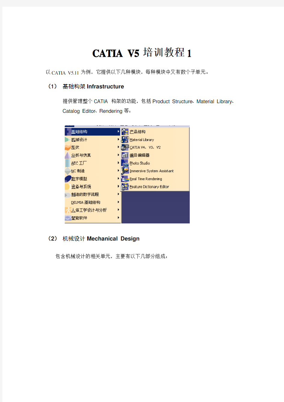
(1)基础构架Infrastructure
提供管理整个CATIA 构架的功能,包括Product Structure、Material Library、Catalog Editor、Rendering等:
(2)机械设计Mechanical Design
包含机械设计的相关单元,主要有以下几部分组成:
(3)造型Shape
提供曲面与逆向工程设计单元,可以自由塑造不规则曲面,利用手绘草图来构件曲面。
(4)分析与仿真Analysis & Simulation
提供实体的网格划分(mesh)与静力、共振等有限元分析功能,并可输出网格分割数据共其它分析软件使用。
(5)APC 工厂布局
提供工厂的规划建制功能。
(6)数控加工NC Manufacturing
包含两轴到五轴加工的编程能力,并支持快速原型功能(STL Rapid Prototyping)。
(7)数字化仿真Digital Mockup
包含动态机构仿真、装配配合空间分析、产品功能分析与功能优化等。
(8)设备与系统Equipment and Systems
提供各种系统设备的建置,管路和电线的配置以及电子零件配置等功能。
(9)制造的数字化过程Digital Process for Manufacturing 提供在三维空间中进行产品的特征、公差与配合标注等功能。
(10)人体工学设计与分析Ergonomics Design&Anaysis
提供人体模型,并可对产品进行人体空间分析。
(11)智能软件Knowledgeware
一. 基本使用环境
本章主要介绍CA TIA用户的基本操作界面、使用技巧、树结构(Tree)以及文件File、编辑Edit和视图View等菜单的操作等。
2.1 CATIA 的用户界面CATIA User Interface
操作窗口
菜单及工具条
CA TIA对话框的组成
2.2 操作技巧
1. 鼠标的使用
(1)使用三键鼠标,利用鼠标可以完成数种功能,包括选择和编辑对象、移动视角、右击打开弹出式菜单、旋转视角、物体的缩放等,具体使用如下:(2)选择和编辑对象:点击MB1
(3)移动物体Translate:用MB2,按住中间不放,则物体随鼠标的移动而移动。
(移动物体的视角)
(4)打开弹处菜单:用MB3,在物体上单击右键,可打开快捷菜单。
(5)旋转物体Rotate:用MB2+MB1或MB2+MB3,现按中键,再按右键或左键不放,移动鼠标即可。点击中键可确定旋转中心。
(6)物体缩放ZOOM:按中键MB2,再点击右键MB2或左键MB1,向上是放大物体,向下是缩小。
2. 指南针Compass
指南针(Compass)代表三维坐标系统。帮助用户建立空间概念和了解坐标系统。You can use a graphic manipulator referred to as the 3D compass to perform a certain number of manipulations on certain objects created and managed by certain applications (for example, Product Structure, Assembly, FreeStyle Shaper, DMU Navigator, etc.). 通过指南针,用户可以在Product Structure, Assembly, FreeStyle Shaper, DMU Navigator等过程中完成一系列的操作,如指定物体左X Y Z三轴的旋转和平移、在XY YZ ZX平面上的移动等,提高操作效率。
The 3D compass lets you:
●manipulate viewpoints using the mouse and compass: this is just another way of
panning and rotating all objects in the document at the same time
●move and rotate non-constrained objects using the mouse and compass
Moving objects in this context means physically moving them so as to
redefine their spatial coordinates with respect to the absolute axis system
in a document. Moving should not be confused with panning an object,
which simply modifies the viewpoint from which you look at an object: the
position of the object in the document remains the same.
●move and rotate non-constrained objects using the Edit... contextual command
●lock the compass orientation
●snap the compass automatically onto a selected object
●set the plane in which you move objects parallel to the screen
●switch the privileged plane(优先)to the XZ or YZ planes of the compass
●use the privileged plane as a working plane in applications such as the FreeStyle
Shaper application, for example, when manipulating control point manipulators on planar patches and curves.
注意:You can use the 3D compass to manipulate non-constrained objects, in other words, objects not linked together by constraints. However, you can manipulate groups of objects in assemblies which are linked to each other by constraints.
使用指南针操作视点(Manipulating Viewpoints)的方法如下:
(1)自由旋转:抓住指南针Z轴顶点,移动鼠标
(2)旋转:抓住指南针平面上的弧线,移动鼠标
(3)轴向移动pan along the direction of any axis (X, Y or Z) of the compass:抓住指南针上的轴线,移动鼠标
(4)平面移动:抓住指南针上的平面,移动鼠标。
(5)单一物体的移动:抓住指南针上的红色方块,移动指南针到物体的任何一点,便可直接对物体进行平移、旋转等操作。在装配时,此功能非常有用。
(6)快捷菜单:在指南针上单击右键,弹出快捷菜单
●锁定当前方向Lock Current Orientation:固定当前视角
●将优先平面的方向锁定为与屏幕平行的方向Lock Privileged Plane Orientation
Parallel to Screen:
●使XY平面为优先平面Make ZX Plane Privileged Plane:指定XY平面为指南针的
基准面。
●使YZ平面为优先平面Make ZX Plane Privileged Plane:
●使ZX平面为优先平面Make ZX Plane Privileged Plane :
●使优先平面最大程度可见Make Privileged Plane Most Visible:
●自动抓取选定对象Snap Automatically to Selected Object:但击此项,再单击一个物
体,指南针便指定到确定的物体上
3. 选择物体Select Objects
使用鼠标选择物体常用以下几种方法:
(1)单选Simple Selection:
●直接用鼠标的MB1单击物体;
●在左边的“特征树Selection of Geometry of Tree Feature”上单
击物体的名称,即可选择对应的物体,被选择的物体会高亮显示。
Selection of geometry or of feature(s) in the tree
(2)一次选多个物体Selection of Several Objects (Multi-selection):按Ctrl 键,用鼠标MB1点击多个物体,即可选择多个物体。
(3)直接用“编辑Edit”菜单中的“搜索Search”,按指定的属性选择有同一属性的物体。
(4)利用“选择工具SelectToolbar”拖动鼠标
Select the Select icon
to enter selection
mode, if it is not already activated.
Drag (using the left mouse button).
A bounding outline will appear as you drag:
Drag the bounding outline until the object(s) you want to select is(are) completely inside the bounding outline. (The objects must be completely
inside the bounding outline: if not, they will not be selected. )
Release the mouse.
The objects will be highlighted to indicate they have been selected.
4. 使用层和层过滤器Using Layers and Layer Filters
几何属性工具条(The Graphic Properties toolbar)
设置物体的几何属性。
The Painter icon lets you apply graphic properties
from one object to another. To do so:
?select the object(s) you want to apply new
graphic properties to
?click the Painter icon
?select the reference object, i.e. the object from
which you will copy the graphic properties
(2)分配物体到层Assigning Objects To Layers
Once you have assigned objects to layers, you then create
visualization filters (refer to "Using Visualization Filters") which allow you to display only those objects located on specific layers referenced by the visualization filter.
"None" in the Layer box: indicates that there is no current layer, which guarantees(保证)that all the contents of your document are visible.
You can assign objects to "None": any object assigned to "None" will
always be visible.
The following layers are always available:
●None
●0 General
● 1 - 999 (even though they are not visible at first in the Layer
list).
These layers cannot be deleted.
分配步骤:
I.打开几何属性工具条
II.选择物体
III.点击几何属性工具条的the arrow on the Layer bo x, 然后在层列表
中选择所要放置物体的层,即可使物体加入指定的层。
(3)增加和命名层Adding and Naming Layers
I. Select the 视图View->工具条Toolbars->几何属性Graphic
Properties command to look at the Graphic Properties toolbar. 打
开“几何属性工具条”。
II.Click the arrow on the Layer icon box, then select the Other Layers...
command from the list. The Named Layers dialog box appears:
III. Click the New button.
The layer "1", is added to the list, and the name "Layer 1" is assigned
automatically:
IV. Click OK.
(4)使用可视过滤Using Visualization Filters
A visualization filter is a group of layers. You then apply the filter to visualize (or not) only those objects located on the layers in the filter.“可视过滤”是一个层组,它可以使仅在过滤器中那些层里的物体可视或不可视。
步骤:
Select the Tools -> Visualization Filters... command
The Visualization Filters dialog box appears。The default current
filter "All visible" is applied automatically: it lets you see all the
contents of the document. This filter cannot be deleted.
Click the New button.
The Visualization Filter Editor dialog box appears, allowing you
to build the filter from the following building blocks:
C riterium: this list box contains the operators =, !=, >, <, <= and >=; the default is "="
t he list box to the rightlists the named layers (you can type any layernumber between 0
and 999)
A nd and Or buttons provide you with the corresponding logical functions for combining
layers.
2.3 File菜单
1.CATIA的文档类型(CATIA Documents)
CA TIA文档即是CATIA数据按某种格式存储的格式文件,CA TIA按数据建立的不同而
有不同类型的数据存储格式文件,常用的类型见下图所示:
更为详细的文件类型说明可见后附录1的内容。
2.文件File菜单项
File菜单中的项目大都是基本功能,但要注意的“新建自New Form”命令。
You may want to create a new document whose basic characteristics are the same as
an existing document.
They will be identified by the icon in
the specification tree .
(1)创建文件
I. Click the New icon or select the
File->New... command:
出现新建文件类型选择框,选择对应的类型。
II. In the New dialog box, double-click the
document type or select it then click OK.
Choose the document type from the following:
Part、Drawing、Product、Analysis、CatalogDocument、Process、
ProcessLibrary
(2)保存管理Save Manage
The "Save Management..." command lets you save all your modified documents
under a new name and a new location.
Here are the various states that may be assigned to a document:
N ew新:
identifies a newly created document. You have to select a file name in order to save it O pened已打开: identifies a non-modified document open in your session
M odified已修改:identifies a document which has been modified in your session
R ead Only只读: identifies a modified and read-only document. You have to specify a
new name for this document if you want to save it
O pened Read Only打开只读: identifies a non-modified, read-only document open in
your session
S ave: identifies a document that will be saved
S ave Auto: i dentifies a dependent document that will be saved.
(3)桌面Desk
可以把所有Catia窗口里已打开的文件列成树形树,已方便用户管理。
(4)打印Print
可以把指定的文件通过打印机打印出来。
(5)发送至Send To
可以将文件发送至其它地方,以E-Mail和Directory(文件夹)的方式进行发送。
●Sending Version 5 Data In the Mail (Windows Only)
●Copying Version 5 Data To a Directory or Diskette
2.4 编辑Edit菜单
编辑菜单大多数项目都是基本功能,这里主要讲述Search查找、Selection Sets选择集
和Define Selection Set定义选择集。
1. 查找Search
可以让用户查找到同属性的对象,包括:
●具有特殊名称或同颜色的物体;
●指定线性、线宽;
●显示或隐藏的物体;
●物体的特性;
●有共同属性值的物体(材料、尺寸等);
●用相同模块建立的物体。
在查找功能中,有三种模式,General常规、Advanced Mode高级模式和Favorite Mode 收藏。
用General和Advanced Mode所查找的对象可以直接加入到收藏夹(Add to Favorites)中,以便与在“Favorite Mode”下查找使用。
2. 选择集编辑Selection Sets Edit
可以将同一属性或其它作用的物体放置的一起,形成选择集(Selection Set)。选择集的
建立和编辑可以在Edit->Selection Sets Edi t项下进行。
(1)定义选择集Selection Set:
选择“编辑Edit”->“选择集编辑Selection Sets Edit…”->点击“Create Set”按钮,对要建立的选择集命名,然后选择选择集所要包含的物体(在“Add
Element”状态下)->点击“确认”,即可建立一个新的选择集。
(2)编辑选择集:
进入菜单,在“选择集编辑”对话框中,可以删除选择集,也可以对选择集内的物体进行添加和删除。
●点击所要编辑的选择集,点击“Delete Set”,即可删除选择集;
●若想在选择集中加入物体,则点击所要编辑的选择集,单击想要加入的
对象,然后点击“Add Element”即可;
●若想删除选择集中的对象,则点击选择集,再点击选择所要删除的对象,
然后点击“Remove Element”即可。
3. 选择集
选择“编辑Edit”->“选择集Selection Sets…”,可以选择所选择的选择集中的对象。
4. 链接Links
可以把别的文件或对象链接起来,主要在装配设计中使用。
5. 特性Properties
对对象的属性进行修改和确认,这些属性包括颜色Color、名称、线条的粗细、线形、透明度Transparency等。
选择“编辑Edit”->“特性Peoperties”,或在选择物体上用鼠标的右键点击弹出快速菜单,选择“特性”,也可以用快捷键Alt+Enter;
●在“图形Graphic”中,“当前选择Current Selection”代表当前所选对象的名
称,可以在“Feature Properties”选项中更改,在“Feature Properties”中显示对象建立的日期Date Created和最后更改日期Last Modified。
●在“图形Graphic”中,可以更改填充颜色Color、透明度Transparency,从边
线Edges和线段和曲线Lines And Curves中选择改变物体边线、线段和曲线的颜色、线形和线宽。也可以改变点Point的颜色和符号Symbol
●“Graphic”中的“Show,Pick and Layer”下的“Shown”和“Pickable”表
示对象目前所处的状态。取消“Pickable”,则在屏幕上点击不到此对象。
●“Mechanical”选项卡中,可以把执行的操作(如倒角、倒圆等)取为“无效
deactivated”,即此操作不发生作用;当对象或操作执行发生错误或需要更新时,“Unresolved无解的”和“To Update更新”选项便会高亮显示,提供用户注意。
2.5 视图View菜单功能
在CATIA中,“视图View”菜单随不同的模块而稍有区别,下面说明其中公共部分。
CATIA线束设计入门教程 一、电器零件建立 关于CATIA CATIA是世界上一种主流的CAD/CAE/CAM 一体化软件。在70年代Dassault Aviation 成为了第一个用户,CATIA 也应运而生。从1982年到1988年,CATIA 相继发布了1版本、2版本、3版本,并于1993年发布了功能强大的4版本,现在的CATIA 软件分为V4版本和 V5版本两个系列。V4版本应用于UNIX 平台,V5版本应用于UNIX和Windows 两种平台。V5版本的开发开始于1994年。为了使软件能够易学易用,Dassault System 于94年开始重新开发全新的CATIA V5版本,新的V5版本界面更加友好,功能也日趋强大,并且开创了CAD/CAE/CAM 软件的一种全新风格。 CATIA是英文 Computer Aided Tri-Dimensional Interface Application 的缩写,是由法国Dassault宇航公司从七十年代开始开发,并应用于宇航工业;八十年代初,Dassault 集团成立Dassault Systems公司,专门负责CATIA的技术开发,并将CATIA做为商业软件推向市场。 CATIA在发展的二十年中在世界围已有1万2千多家用户在使用共13万套以上的CATIA 为其工作,大到飞机、载人飞船和汽车,小到螺丝钉和钓鱼杆,CATIA都可以根据不同规模、不同应用定制完全适合本企业的最佳解决方案。除了在汽车及汽车、航空航天领域的统治地位不断增强,同时,CATIA也大量地进入了其他行业,如机车制造、通用机械、家电、船舶等。 CATIA源于航空航天工业,是业界无可争辩的领袖。CATIA从产品的概念设计到最终产品的形成,以其精确可靠的解决方案提供了完整的2D、3D。参数化建模、电子样机建立及数据管理手段满足商业防御和航空领域应用的需要,同时,作为一个完全集成化的软件系统,CATIA将机械设计、工程分析仿真、数控加工及CATweb网上解决方案有机地结合在一起,为用户提供了严密的无纸工作环境,特别是CATIA中专业的航空专用模块,如:航空钣金设计、航空复合材料设计辅层、管路设计及分析、电路布线及生产等等使CATIA拥有了最宽广的专业覆盖面,从而帮助客户达到缩短设计生产周期,提高质量,减少成本的目的。CATIA 引以自豪的主要项目是例如波音777成功地用100%数字模型无纸加工完成。这在航空业中从来没有过,堪称业界第一。目前CATIA在航空、航天领域的装机量已经达到本行业所有装机量的60%。在中国,CATIA也取得了令人嘱目的成绩,、、、、、、等航空飞机厂无一例外的都选用CATIA做为其核心设计软件。 CATIA是汽车工业的事实标准,是欧洲,北美和亚洲顶尖汽车制造商所用的核心系统。CATIA在造型风格,车身及引擎设计等具有独特的长处,为各种车辆的设计和制造提供了全方位的解决方案。CATIA涉及产品、加工和人三个关键领域,电子样机设计环境使得汽车厂家能够快速及时的响应和满足客户的需求,向市场推出各种型号的汽车,满足不同消费群众,其独具的可伸缩性和并行工程能力可显著缩短产品上市时间。许多国际知名的汽车厂家比如Honda、BMW、Suzuki等都使用CATIA作为他们的新车型的开发平台,而国包括一汽集团、
1. F3------隐藏目录树; 2. 鼠标左键(或右键)+鼠标中键视图旋转;鼠标中键视图平移;鼠标中键视图放大缩小; 3. Alt + Enter = 性质; 4. shift 加中键出现红色方块后拖拉,快速放大指定局部,指定观察方向; 5. 先按CTRL 再加中键是放大缩小;先按中键再加CTRL 是是对象旋转; 6. 对象旋转时,外面会出现红色的圆形区域,在圆形区域内是XYZ轴的任意旋转,在圆形区域外是针对Z轴的特定旋转; 7. Press any keyboard arrow, the preselection navigator appears. ctrl+F11,出现物体选择器。 8. Ctrl + Page up ----zoom in Ctrl + Page down ----zoom out Shift + 上下左右箭头----rotate Ctrl +上下左右箭头----pan Ctrl +shift + 左右箭头----rotate shift+F3 --work on specification tree shift +F2--specification tree overview MB3+Customize--可自定义 Alt+mb2 --循环选择 ctrl+u --再生(装配时用的着) CTRL+鼠标滚轮放大缩小特征树 9. 三维零件建模时的命名:因为具有相同零件名字的零件不能在装配环境中同时被调用,所以在进行三维零件建模之前,可以事先将系统默认的模型树中的零件名字改成该零件文件保存时将要用的名字。这样不仅避免了零件名字的重复,还可方便零件的保存; 10. 公差标注:在零件的工程图中时常有如ф39±0.05的公差标注,CA TIA默认字体SICH 无法按要求进行标注,标出的是ф39 0.05的形式。这时可以将公差类型设置为TOL-1.0并用αCA TIA Symbol字体标注。 11. 鼠标右键在工程图标注中的应用: (1) 在半剖视图中标注孔的尺寸时,尺寸线往往是一半,延长线也只在一侧有。如果直接点击孔的轮廓线,按左键确认,出现的是整个尺寸线。 可以在还未放置该尺寸前点击鼠标右键,选择“Half Dimension”,即可标注出一半尺寸线。 (2) 标注两圆弧外边缘之间的距离时,当鼠标选中两圆弧后,系统自动捕捉成两圆心之间的距离尺寸,此时同样在未放置该尺寸之前点击右键, 在弹出菜单中的“Extension Lines Anchor”中选择所要标注的类型; (3) 工程图中有时需要标注一条斜线的水平或垂直距离,或者要标注一条斜线的一个端点与一条直线的距离,这时可以在选中要标注的对象后, 在右键弹出菜单中选择“Dimension Representation”中所需的尺寸类型。两直线角度尺寸的标注也可以通过弹出菜单中的“Angle Sector”选 择所需的标注方式; 12. 重新选择图纸:若在将零件转化成工程图时选错了图纸的大小,如将A3选成A4纸,可以在“Drafting”环境中点击“File”→“Page
CATIA Training COPYRIGHT DASSAULT SYSTEMES 2002 Version 5 Release 9 June 2002 C A T I A B a s i c s D e t a i l e d S t e p s
Table of Contents Manipulating Objects (3) Step 1: Start and Open a document (3) Step 2: Change the Part Number (4) Step 3: Change graphic properties (5) Step 4: Open a new Document (7) Step 5: Copy / Paste a PartBody (8) Step 6: Modify a feature (8) Step 7: Use the Compass (9) Step 8: Hide and delete a Body (11)
Manipulating Objects In this exercise you will learn basic tools to manipulate documents and get familiar with standard CATIA V5 interface. Step 1: Start and Open a document 1. Start Catia. 2. Open CATCOMStep-dolt.CATPart and select mm as model unit by going to Tools + Options + General + Units.
CATIA V5R17 - FACT SHEET
CATIA V5R17 boosts Innovation for Product Excellence
? ? ? ? Introduction What’s New at a Glance Overview Detailed Description
INTRODUCTION CATIA V5 is the leading solution for product excellence. It addresses all manufacturing organizations, from OEMs, through their supply chains, to small independent companies. The range of CATIA V5’s capabilities allows for its application in a wide variety of industries, from aerospace, automotive, industrial machinery, electrical, electronics, shipbuilding, plant design, and consumer goods, to jewelry and clothing. CATIA V5 is the only solution that covers the complete product development process, from product concept specifications through to product-in-service, in a fully integrated manner. Based on an open, scalable architecture, it facilitates true collaborative engineering across the multidisciplinary extended enterprise, including style and form design, mechanical design, equipment and systems engineering, digital mock-up management, machining, analysis, and simulation. By enabling enterprises to reuse product design knowledge and accelerate development cycles, CATIA V5 helps companies speed-up their response to market needs. In conjunction with ENOVIA for collaborative product lifecycle management, SIMULIA for engineering quality and DELMIA for production performance, CATIA V5 is a key component of V5 PLM.