
FUNDAMENTALS AND APPLICATIONS OF DIELECTRIC-BARRIER DISCHARGES
U. Kogelschatz
ABB Corporate Research Ltd, 5405 Baden, Switzerland, ulrich.kogelschatz@https://www.doczj.com/doc/316572784.html,
Received: 24.05.2000
1. Introduction
Dielectric-barrier discharges (DBDs), also referred to as barrier discharges or silent discharges have found a number of interesting industrial applications in addition to the historical ozone generation. The generation of powerful coherent infrared radiation in CO 2 lasers and of incoherent ultraviolet (UV) or vacuum ultraviolet (VUV) excimer radiation in excimer lamps are examples of more recent developments. VUV excimer radiation generated in DBDs can excite phosphors to emit visible light. This is the basis of mercury-free fluorescent lamps and of flat plasma display panels that will be used as wall hanging TV sets. Processes like pollution control and surface treatment with DBDs show great promise for the future.
The most important characteristic of DBDs is that non-equilibrium plasma conditions can be provided at elevated pressure, for example atmospheric pressure. In DBDs this can be achieved in a much simpler way than with other alternative techniques like low pressure discharges, fast pulsed high pressure discharges or electron beam injection. The flexibility of DBD configurations with respect to geometrical shape, operating medium and operating parameters is remarkable. In many cases discharge conditions optimized in small laboratory experiments can be scaled up to large industrials installations. Efficient low cost power supplies are available up to very high power levels.
2. Discharge physics
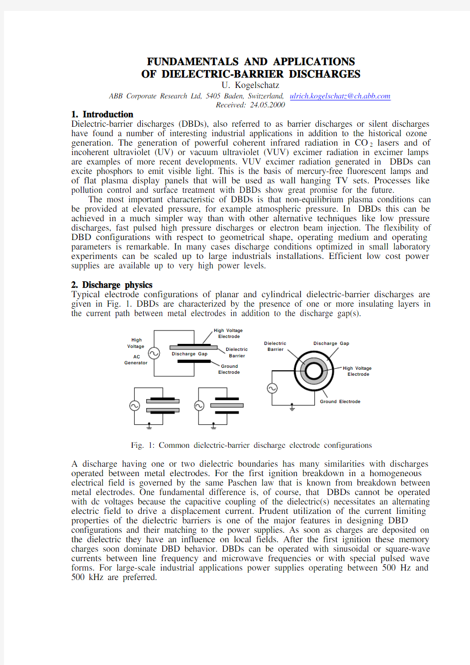
Typical electrode configurations of planar and cylindrical dielectric-barrier discharges are given in Fig. 1. DBDs are characterized by the presence of one or more insulating layers in the current path between metal electrodes in addition to the discharge gap(s).
High
Voltage Barrier Dielectric Discharge Gap
Electrode
AC Fig. 1: Common dielectric-barrier discharge electrode configurations
A discharge having one or two dielectric boundaries has many similarities with discharges operated between metal electrodes. For the first ignition breakdown in a homogeneous electrical field is governed by the same Paschen law that is known from breakdown between metal electrodes. One fundamental difference is, of course, that DBDs cannot be operated with dc voltages because the capacitive coupling of the dielectric(s) necessitates an alternating electric field to drive a displacement current. Prudent utilization of the current limiting properties of the dielectric barriers is one of the major features in designing DBD configurations and their matching to the power supplies. As soon as charges are deposited on the dielectric they have an influence on local fields. After the first ignition these memory charges soon dominate DBD behavior. DBDs can be operated with sinusoidal or square-wave currents between line frequency and microwave frequencies or with special pulsed wave forms. For large-scale industrial applications power supplies operating between 500 Hz and 500 kHz are preferred.
2.1 Filamentary dielectric-barrier discharges
In atmospheric pressure gases breakdown in a plane parallel gap with insulated electrodes normally occurs in a large number of individual tiny breakdown channels, referred to as microdischarges. When an overvoltage is applied to the discharge gap electron avalanches soon reache a critical stage where the local “eigenfield” caused by space charge accumulation at the avalanche heads leads to a situation where extremely fast streamer propagation becomes possible. As a result thin conductive channels are formed. The properties of these microdischarges have been investigated experimentally as well as theoretically [1-10]. Typical parameters for air discharges in a 1 mm gap are summarized in Table 1.
Table 1: Characteristic microdischarge properties in air at atmospheric pressure
Duration: Filament Radius: Peak Current Current Density:10-9-10-8 s
about 10-4 m
0.1 A
106 – 107 A m-2
Total Charge:
Electron Density:
Mean Electron Energy:
Filament Temperature:
10-10 – 10-9 C
1020 - 1021 m-3
1-10 eV
close to average gas
temperature in the gap
At a dielectric surface the microdischarge channels spread into surface discharges covering a much larger region than the original channel diameter. The microdischarge filaments can be characterized as weakly ionized plasmas with properties resembling those of transient high pressure glow discharges. They start when the breakdown field is reached locally and extinguish when the field is reduced to such an extent that electron attachment and recombination dominate over ionization. Due to charge build-up on the dielectric surfaces the field at the location of a microdischarge collapses within a few ns after breakdown, thus terminating the current flow at this location. The short duration results in little transient gas heating of the current channel. Humidity tends to increase the strength of a microdischarge while irradiating the cathode with UV photons tends to decrease it. The dielectric barrier limits the amount of charge and energy deposited in an individual microdischarge and distributes the microdischarges evenly over the entire electrode surface. As long as the external voltage is rising additional microdischarges are initiated at new locations because the presence of residual charges on the dielectric has reduced the electric fields at positions where microdischarges have already occurred. When the voltage is reversed, however, the next microdischarges will form at old microdischarge locations. Consequently, high voltage low frequency operation tends to spread the microdischarges, while low voltage high frequency operation tends to reignite the old microdischarge channels every half period. This memory effect due to charge accumulation on the dielectrics is a dominant feature in all DBDs.
2.2 Diffuse dielectric-barrier discharges
It has been demonstrated that homogeneous diffuse discharges can also be obtained in DBD configurations even at atmospheric pressure. In 1976 K. Donohoe obtained a uniform glow discharge with pulsed excitation in a helium/ethylen mixture [11]. S. Okazaki and her group at Sophia University in Tokyo did pioneering work in this field using sinusoidal feeding voltages in different gases with and without additives [12-14]. They proposed the term APG, standing for atmospheric pressure glow. To generate uniform glow discharges at atmospheric pressure in helium, air, argon, oxygen and nitrogen even when using a 50 Hz power source they used an electrode configuration consisting of two metal foils covered with a special metal mesh and ceramic plates. More detailed investigations followed by F. Massines and her group at Toulouse [15, 16]. Apparently independently of these investigations, a group around J.R. Roth at the University of Tennessee at Knoxville re-invented what they called an OAUGDP (one atmosphere uniform glow discharge plasma) and even obtained a US patent for a "Method and apparatus for glow discharge plasma treatment of polymer materials at atmospheric pressure" [17].
Glow discharges in atmospheric pressure gases were already mentioned by von Engel, Seeliger and Steenbeck in 1933 [18] and by Gambling and Edels in 1956 [19]. The subject became an important issue when transversely excited atmospheric pressure (TEA) lasers were investigated in N2, in CO2/N2/He, and in excimer forming gas mixtures. It was found that
sufficient preionization by x-rays, electron beams or by double-discharge techniques helped to establish such a uniform glow phase. Necessary requirements of a minimum initial electron density were formulated by Palmer [20] and by Levatter and Lin [21]. One requirement for establishing a volume-stabilized glow discharge is that the preionization electron density is large enough to cause appreciable overlap and coalescence of primary avalanche heads and smoothing of space-charge field gradients at the stage when streamer formation would otherwise occur. More recently Brenning et al. [22] formulated more detailed conditions for obtaining homogenous high-pressure pulsed avalanche discharges. They point out the importance of an additional minimum preonization rate just prior to and during breakdown. The most important quantity is the effective primary ionization coefficient áeff (including all attachment and detachment processes) at the moment of breakdown or, more precisely, its derivative with respect to the reduced field: d(áeff/n)/d(E/n). This quantity is strongly effected by impurities, gas additives and the presence of metastables and residual ions. In dielectric-barrier discharges we can make use of residual species from the previous half period. Thus, in addition to the already mentioned memory charges on the dielectric surface(s), we also have a memory effect in the volume if the repetition frequency is properly chosen. Also special dielectric properties can help to establish a homogeneous volume discharge. As Tepper et al.
[23] demonstrated, electret dielectrics are capable of accumulating appreciable amounts of charges on the surface. Supported by the applied voltage the charges are trapped uniformly on the surface. When the electric field changes its polarity and exceeds a certain threshold value, the charge carriers are expelled spontaneously from the surface and initiate a homogeneous discharge.
Up to now it is difficult and tricky to reliably control homogeneous glow discharges at atmospheric pressure. For instance, changes of the electrode configuration or small variations of the amplitude or repetition frequency of the applied voltage can cause a transition into a more stable filamentary discharge mode. For industrial applications this could be a severe drawback compared to filamentary discharges. If however reliable control can be provided and if an average energy transfer into the discharge can be obtained comparable to that of filamentary discharges, this type of discharge may become of particular interest for certain industrial applications.
3. Applications of dielectric-barrier discharges
Most industrial DBD applications utilize filamentary discharges [3, 9, 24]. The technology for large-scale applications was initially developed with ozone generation in mind. In the mean time novel DBD applications have established new markets that reach annual sales amounting to at least ten times the original ozone market.
3.1 Industrial ozone generation
Technical ozone generators use cylindrical discharge tubes of about 20-50 mm diameter and 1-3 m length [25, 26]. Borosilicate glass tubes have for a long time been the favorite dielectric material. They are mounted inside stainless steel tubes to form annular discharge gaps of about 1 mm radial width. Metal coatings, e.g. thin aluminum films, inside the glass tubes serve as high voltage electrodes, which are contacted by metal brushes. Modern high-performance ozone generators use special layered dielectrics with characteristics optimized for ozone formation. Large ozone generators use several hundred discharge tubes in big steel tanks to provide the required electrode area for mass ozone production. The outer steel tubes are welded between two end flanges and form a sealed cooling compartment. A transverse water flow cools the steel tubes in a classical heat exchanger configuration. Efficient cooling is essential for good ozonizer performance.
Modern high-power ozone generators take advantage of semiconductor power conditioning. They utilize thyristor or transistor controlled frequency converters to impress square-wave currents or special pulse trains in the medium frequency range. Typical operating frequencies are between 500 Hz and 5 kHz. Using this technology, applied voltages can be reduced to the range of about 5 kV. With large ozone generators power factor compensation
has become an important issue. Typical power densities now reach 1-10 kW/m 2 of electrode area.
Large ozone generating facilities produce several hundred kg ozone per hour at a power consumption of several MW. The ozone production capacity of a big ozone generator is of the order 100 kg/h. Progress with respect to attainable ozone concentrations and energy consumption has continued to be achieved in recent years [27]. It has been suggested that ozone generation might be further improved by homogeneous discharge conditions [28-31].3.2 Excimer lamps and plasma displays
Excimer lamps, spontaneous emission sources based on excimer formation, can be pumped by pulsed or dc longitudinal discharges, by preionized pulsed transverse discharges, by microwave discharges or by dielectric-barrier discharges. More recently, discharges in supersonic jets, constricted glow discharges and microhollow cathode discharges have also been proposed to generate excimer emission. When DBDs are operated in high-pressure rare gases or rare gas/halogen mixtures each microdischarge can act as an intense source of ultraviolet (UV) or vacuum ultraviolet (VUV) radiation. During the last decade powerful and efficient excimer lamps have been developed [3, 32-36] and have found several applications in industrial UV induced processes [9, 24, 33, 37-39]. For large-scale industrial applications dielectric-barrier discharges using fairly simple discharge configurations currently represent the most mature excimer lamp technology. Their main advantage is simplicity, lack of internal electrodes, high efficiency and low cost. Sealed lamps of different planar and cylindrical geometries are common (Fig. 2). Recent applications of excimer lamps include UV curing of photoreactive polymers, photo-deposition of large area or patterned thin metal or semiconductor films, of high- and low-dielectric-constant insulating layers, photo-assisted low-temperature oxidation of Si, SiGe and Ge, polymer etching and microstructuring of polymer surfaces. Applications investigated so far clearly demonstrate that high power excimer lamp systems can provide an interesting alternative to excimer lasers for industrial large-scale low-temperature materials processing.
UV Transparent HV AC Generator
Fig. 2: Sealed cylindrical and planar dielectric-barrier discharge excimer lamp configurations
The width of the discharge gap ranges from 0.1 mm to several mm. Filling pressures range from 104 to 5·105 Pa. In many cases a third buffer gas (He, Ne) is added to the binary excimer forming mixture. This facilitates ignition and provides additional control over the electron energy distribution. Operating frequencies range from 50 Hz to some GHz, applied voltages from a few hundred V to several kV. Commercial excimer lamps are offered for the wavelengths 126 nm (Ar 2*), 146 nm (Kr 2*), 172 nm (Xe 2*), 222 nm (KrCl *) and 308 nm (XeCl *). For UV curing applications cylindrical XeCl * lamps up to 2 m length are available.Typical efficiencies range from 5–40%. In recent years also powerful and efficient XeI * and XeBr * lamps radiating at 253 nm [40] and 282 nm [41], respectively, have been investigated.Most excimer lamps concentrate their emission in a narrow wavelength region. Even at high electrical input powers cooled versions can operate close to room temperature.
By far the most important representative is the xenon excimer lamp. It reaches an efficiency of 40%. Phosphors can be used to transform its VUV radiation to visible light. This
wavelength conversion is utilized in mercury-free fluorescent lamps, in flat panels illuminating liquid crystal displays and in flat plasma display panels with up to 1.5 m picture diagonal. In tiny addressable DBD cells of 0.1 mm electrode spacing and 0.2 mm width xenon VUV radiation is converted to red, green or blue image points by activating internally applied phosphor layers. Gas mixtures containing 5-10% Xe in Ne or He are used at pressures of 50-70 kPa. The operating voltage is only 200-300 V. Multi-billion dollar investments in production facilities for these flat television screens in Japan, Taiwan and South Korea have recently led to a new dimension of large-scale industrial DBD applications. In 1998 already about 50’000 flat plasma displays with 1 m picture diagonal were sold. The market volume is expected to increase to 5 million sets by the year 2005 [42].
3.3 Silent-discharge CO2 lasers
DBDs have also found applications in high power CO2 lasers. Based on their experience with ozone generators N. Tabata and S. Yagi at Mitsubishi Electrical Corporation developed an industrial high power laser. This SD CO2 laser (SD stands for silent discharge) soon became the most successful commercial laser for material processing on the Japanese market. The water-cooled plane metal electrodes, separated by 50 mm, are covered with glass or alumina dielectrics. A high-velocity transverse gas flow passes the discharge gap at a speed of 50-80 m/s for heat removal and discharge stabilisation. Due to the large fraction of helium in the laser gas mixture (about 30%) and the low operating pressure (6.4 kPa) the discharge appears uniformly diffused. Operating at 160 kHz there is not enough time for the ions to decay or to be swept out between succeeding half periods . As a consequence, the discharge behaves very much like a resistive load (ion trapping discharge). Nearly diffraction limited infrared radiation at the wavelength ?=10.6 μm is obtained with output powers up to 5 kW. The efficiency exceeds 10%. The main application of this SD CO2 laser is high speed welding and cutting of thick metal plates and other materials [43].
3.4 Pollution control
Applications of DBDs for pollution control and for the destruction of poisonous compounds have received growing attention. After initial work on military toxic wastes an increasing number of investigations have been devoted to the treatment of nitrogen oxides and sulphur oxides in flue gases, and to the decomposition of volatile organic compounds (VOCs). Typical examples are hydrocarbons, chlorocarbons and chlorofluorocarbons (CFCs). Contamination of exhaust air streams with gaseous hydrocarbons or organic solvent vapors occurs in many industrial processes, e. g. in chemical processing, in print and paint shops, in semiconductor processing as well as in soil remediation and water treatment. Recent reviews of the subject were published by B.M. Penetrante et al. [44, 45] and by L.A. Rosocha [46, 47].
Many hazardous organic molecules are readily attacked by free radicals, electrons or UV photons. DBDs are utilized to provide reactive species such as N2*(A3óu+), N2*(B3Πg), O2*(a1?g), O(1D), O(3P), H, OH, and N. These species are initially generated by electron collisions in the microdischarge filaments and subsequently initiate a number of reaction paths generating additional O, OH or HO2 radicals for decomposing pollutants.
3.5 Surface modification and surface coating
Plasma treatment of polymer surfaces to promote wettability, printability and adhesion has a long tradition [48, 49]. In many publications this process is referred to as “corona treatment”. In reality, in most applications a dielectric barrier is used to guarantee stable operation without arc formation. Large-area plastic foils are treated on one or both sides by passing them at high speed through a DBD maintained by an alternating high voltage applied between knife edge electrodes and a rotating drum covered by a dielectric. Electrode assemblies of several parallel knife edges or tube electrodes covered with dielectric layers are also used. Foils up to 10 m width are treated at speeds up to 10 m/s. This application requires discharge powers of about 100 kW. Useful operating frequencies are in the range 10-50 kHz.
As an additional process the deposition of thin films in DBDs has been investigated. A number of authors used homogeneous glow discharges for this purpose [50-52]. An
alternative approach has been taken by J. Salge and co-workers [53-56]. They showed that by using pulsed dielectric-barrier discharges microdischarge properties can be influenced in such a manner that superior surface modification and coatings of excellent quality can be obtained. Special power supplies were developed to generate repetitive pulse trains resulting in improved statistical distribution of the microdischarges across the surface, a prerequisite for uniform treatment. Working in acetylene pin-hole free polymeric films with properties resembling those of polyacetylene were obtained. Also thin deposits of silicon oxide were obtained at atmospheric pressure in an atmosphere of propargyl alcohol vapor and silane. In both cases the surface tension of polypropylene foils could be doubled.
The treatment of surfaces at low temperature and close to atmospheric pressure is an important advantage for large-scale industrial applications. It is to be expected that coating techniques using vapor or gas phase deposition in DBDs and also the annealing and oxidation of sol-gel films subjected to DBDs will be further developed.
4. Outlook: Catalytic dielectric-barrier discharges
In recent years research activities investigating the combination of DBDs and special catalytic substances have evolved. The idea is to enhance the selectivity of the plasma chemical reactions. In catalytic chemistry this selectivity towards certain desired reaction paths can often only be attained at high temperature and pressure. The immersion of a catalyst in a DBD plasma can substantially lower its apparent activation energy and achieve activity already at much lower temperature. Typical examples are different types of packed bed reactors in which pellets or granular materials are introduced into a DBD. We have investigated the inverse geometry, where DBDs are operated in miniature pores of reticulated ceramic foams [57]. The internal surface of the foam structure can be covered with catalytic coatings. This way close contact between the DBD plasma and a very large specific surface area with catalytic activity is established. Conceivable applications are utilization of greenhouse gases and gas to liquid conversion.
5. References
[1] B. Eliasson, M. Hirth, U. Kogelschatz, J. Phys. D: Applied Phys. 20(1987) 1421-1437
[2] V.G. Samoilovich, V.I. Gibalov, K.V. Kozlov, Physical Chemistry of the Barrier
Discharge (in Russian), Moscow State University (1989), English translation: J.P.F.
Conrads, F. Leipold, (Eds.), DVS-Verlag GmbH, Düsseldorf (1997)
[3] B. Eliasson, U. Kogelschatz, IEEE Trans. Plasma Sci. 19(1991) 309-322
[4] D. Braun, U. Küchler, G. Pietsch, J. Phys. D: Appl. Phys. 24 (1991) 564-572
[5] D. Braun, V. Gibalov, G. Pietsch, Plasma Sources Sci. Technol. 1(1992) 166-172
[6] V.I. Gibalov, G. Pietsch, Russ. J. Phys. Chem. 68(1994) 839-846
[7] B. Eliasson, W. Egli, U. Kogelschatz, Pure & Appl. Chem. 66 (1994) 1275-1286
[8] Z. Falkenstein, J.J. Coogan, J. Phys. D: Appl. Phys. 30(1997) 817-825
[9] U. Kogelschatz, B. Eliasson, W. Egli, XXIII. International Conference on Phenomena in
Ionized Gases, Toulouse (1997) Invited Papers, C4-47 to C4-66
[10] Z. Falkenstein, J. Appl. Phys. 81(1997) 5975-5979.
[11] K.G. Donohoe, PhD Thesis, California Institute of Technology, Pasadena, CA (1976)
[12] S. Kanazawa, M. Kogoma, T. Moriwaki, S. Okazaki, 8th International Symposium on
Plasma Chemistry, Tokyo (1987) 1839-1844
[13] S. Kanazawa, M. Kogoma, T. Moriwaki, S. Okazaki, J. Phys. D: Appl. Phys.21 (1988)
838-840
[14] S. Okazaki, M. Kogoma, M. Uehara, Y. Kimura, J. Phys. D: Appl. Phys. 26 (1993) 889-
892
[15] F. Massines, C. Mayoux, R. Messaoudi, A. Rabehi, P. Ségur, Int. Conf. on Gas
Discharges and their Applications, Swansea, UK (1992) 730-733
[16] F. Massines, A. Rabehi, P. Decomps, R.B. Gadri, P. Ségur, C. Mayoux, J. Appl. Phys.
83 (1998) 2950-2957
[17] J.R. Roth, P.P. Tsai, L.C. Wadsworth, US Patent No. 5,403,453 of April 4, 1995
[18] A. v. Engel, R. Seeliger, M. Steenbeck, Z. Physik 85 (1933) 144-160
[19] W.A. Gambling, H. Edels, Brit. J. Appl. Phys. 7(1956) 376-379
[20] A.J. Palmer, Appl. Phys. Lett. 25(1974) 138-140
[21] J.I. Levatter, S. Lin, J. Appl. Phys. 51(1980) 210-222
[22] N. Brenning, I. Axn?s, J.O. Nilsson, J.E. Eninger, IEEE Trans. Plama Sci. 25 (1997) 83-
88
[23]J. Tepper, M. Lindmayer, J. Salge, HAKONE VI, Cork, Ireland (1998) 123-127
[24] U. Kogelschatz, International Conference on Gas Discharges and their Applications,
Swansea, UK (1992) 972-982
[25] U. Kogelschatz: Advanced Ozone Generation, in: Process Technologies for Water
Treatment, S. Stucki (Ed.), Plenum Press, New York (1988) 87-120
[26] U. Kogelschatz, B. Eliasson: Ozone Generation and Applications, in: Handbook of
Electrostatic Processes, J.S. Chang, A.J. Kelly, J.M. Crowley (Eds.), Marcel
Dekker, New York (1995) 581-605
[27] U. Kogelschatz, International Ozone Symposium, Basel (1999) 253-265
[28] A.I. Zakharov, K.S. Klopovskii, A.P. Opsipov, A.M. Popov, O.B. Popovicheva, T.V.
Rakhimova, V.A. Samarodov, A.P. Sokolov, Sov. J. Plasma Phys. 14(1988) 191 – 195
[29] M. Kogoma, S. Okazaki, J. Phys. D: Appl. Phys. 27(1994) 1985-1987
[30] J. O. Nilsson, PhD Thesis, Royal Institute of Technology, Stockholm (1997)
[31] J.O. Nilsson, J.E. Eninger, IEEE Trans. Plama Sci. 25 (1997) 73 – 82
[32] B. Eliasson, U. Kogelschatz, Appl. Phys. B 46 (1988) 299-303
[33] U. Kogelschatz, Pure & Appl. Chem. 62 (1990) 1667-1674
[34] B. Gellert, U. Kogelschatz, Appl. Phys. B 52 (1991) 14-21
[35] K. Stockwald, M. Neiger, Contrib. Plasma Phys. 35(1995) 15 – 22
[36] J.-Y. Zhang, I.W. Boyd, J. Appl. Phys. 80(1996) 633-638
[37] U. Kogelschatz, B. Eliasson, H. Esrom, Materials & Design 12 (1991) 251-258
[38] U. Kogelschatz, Appl. Surf. Sci. 54 (1992) 410-423
[39] I.W. Boyd, J.-Y. Zhang , Nucl. Instrum. Methods in Phys. Res. B 121 (1997) 349-356
[40] J.-Y. Zhang, I.W. Boyd, J. Appl. Phys. 84 (1998) 1174-1178
[41] Z. Falkenstein, J.J. Coogan, J. Phys. D: Appl. Phys. 30 (1997) 2704-2710
[42] S. Mikoshiba, SID Int. Symp., San Jose CA, 1999, Seminar Lect. Notes, M-4/3-M-4/68
[43] Y. Takenaka, M. Kuzumoto, K. Yasui, S. Yagi, M. Tagashira, IEEE J. Quantum
Electron.27(1991) 2482-2487
[44] B.M. Penetrante, S.E. Schultheis, (Eds.), Non-Thermal Plasma Techniques for Pollution
Control, NATO ASI Series, Vol. G 34,Springer, Berlin (1993)
[45] B.M. Penetrante, J. N. Bardsley, M. C. Hsiao, Jpn. J. Appl. Phys. 36 (1997) 5007-5017
[46] L.A. Rosocha in: Plasma Science and the Environment, W. Manheimer, L.E. Sugiyama,
T.H. Stix (Eds.), American Institute of Physics, Woodbury, New York (1997) 261-298
[47] L.A. Rosocha, J. Adv. Oxid. Technol. 4(1999) 247-264
[48] J.L. Linsley Hood, Int. Conf. on Gas Discharges and their Applications, Edinburgh
(1980) 86-90
[49] T. Uehara in: Adhesion Promotion Techniques, K. L. Mittal, A. Pizzi (Eds.), Marcel
Dekker, New York (1999) 139-174
[50] K.G. Donohoe, T. Wydeven, J. Appl. Polymer Sci. 23(1979) 2591-2601
[51] S. Kanazawa, M. Kogoma, S. Okazaki, T. Moriwaki, Nucl. Instrum. Methods in Phys.
Res. B37/38(1989), 842-845
[52] F. Massines, R.B. Gadri, P. Decomps, A. Rabehi, P. Ségur, C. Mayoux, XXII. Int. Conf.
on Phenomena in Ionized Gases, Hoboken NJ (1995) 306-315
[53] U. Reitz, PhD Thesis, Technical University Braunschweig (1992)
[54] R. Schwarz, PhD Thesis, Technical University Braunschweig (1995)
[55] J. Salge J., Surf. Coat. Technol. 80(1996) 1-7
[56] S. Meiners, J.G.H. Salge, E. Prinz, F. F?rster, Surf. Coat. Technol. 98(1998) 1121-1127
[57] M. Kraus, U. Kogelschatz, B. Eliasson, A. Wokaun, 14th International Symposium on
Plasma Chemistry, Praha (1999) 2679-2684
一、选择题 (11·河池)9.科学家的发明与创造推动了人类文明的进程。在下列科学家中,首先发现电磁感应现象的是A.法拉第 B.焦耳 C.奥斯特 D.安培 答案:A (11·苏州)10.如图所示,导体AB水平置于蹄形磁铁的磁场中,闭合开关后,导体AB在下列运动情况中,能使图中小量程电流表指针发生偏转的是 A.静止不动 B.水平向右运动 C.竖直向上运动 D.竖直向下运动 答案:B (11·宿迁)11.如图所示装置可探究感应电流产生的条件,下面操作中能产生感应电流的是 A.保持磁铁静止,将导体棒ab上下移动 B.保持导体棒ab静止,将磁铁左右移动 C.保持导体棒ab静止,将磁铁上下移动 D.保持导体棒ab静止,将磁铁沿导体棒ab方向前后移动答案:B
(11·连云港)5.关于发电机的工作原理,下列说法正确的是 A.电流的热效应 B.电流周围存在磁场 C.电磁感应现象 D.磁场对通电导体的作用 答案:C (11·南京)7.如图所示的四幅图中能说明发电机工作原理的是 答案:A (11·肇庆)9.如右图所示,以下四种措施不能 ..使电流表指针偏转的是 A.将条形磁铁向下插入线圈 B.将条形磁铁从线圈中抽出 C.让条形磁铁静止在线圈中 D.条形磁铁静止而将线圈向上移动 答案:C (11·无锡)11.如图所示为“探究感应电流产生条件”
的实验装置.回顾探究过程,以下说法正确的是 A.让导线ab在磁场中静止,蹄形磁体的磁性越强,灵敏电流计指针偏转角度越大 B.用匝数较多的线圈代替单根导线ab,且使线圈在磁场中静止,这时炙敏电流计指针偏转角度增大 C.蹄形磁体固定不动.当导线ab沿水平方向左右运动时,灵敏电流计指针会发生偏转 D.蹄形磁体固定不动,当导线ab沿竖直方向运动时,灵敏电流计指针会发生偏转 答案:C (11·兰州)13.关于电磁感应现象,下列说法正确的是 A.电磁感应现象中机械能转化为电能 B.感应电流的方向只跟导体运动方向有关 C.感应电流的方向只跟磁场方向有关 D.导体在磁场中运动,能够产生感应电流 答案:A (11·泉州)4.在如图所示的实验装置图中能够说明电磁感应现象的是
FUNDAMENTALS AND APPLICATIONS OF DIELECTRIC-BARRIER DISCHARGES U. Kogelschatz ABB Corporate Research Ltd, 5405 Baden, Switzerland, ulrich.kogelschatz@https://www.doczj.com/doc/316572784.html, Received: 24.05.2000 1. Introduction Dielectric-barrier discharges (DBDs), also referred to as barrier discharges or silent discharges have found a number of interesting industrial applications in addition to the historical ozone generation. The generation of powerful coherent infrared radiation in CO 2 lasers and of incoherent ultraviolet (UV) or vacuum ultraviolet (VUV) excimer radiation in excimer lamps are examples of more recent developments. VUV excimer radiation generated in DBDs can excite phosphors to emit visible light. This is the basis of mercury-free fluorescent lamps and of flat plasma display panels that will be used as wall hanging TV sets. Processes like pollution control and surface treatment with DBDs show great promise for the future. The most important characteristic of DBDs is that non-equilibrium plasma conditions can be provided at elevated pressure, for example atmospheric pressure. In DBDs this can be achieved in a much simpler way than with other alternative techniques like low pressure discharges, fast pulsed high pressure discharges or electron beam injection. The flexibility of DBD configurations with respect to geometrical shape, operating medium and operating parameters is remarkable. In many cases discharge conditions optimized in small laboratory experiments can be scaled up to large industrials installations. Efficient low cost power supplies are available up to very high power levels. 2. Discharge physics Typical electrode configurations of planar and cylindrical dielectric-barrier discharges are given in Fig. 1. DBDs are characterized by the presence of one or more insulating layers in the current path between metal electrodes in addition to the discharge gap(s). High Voltage Barrier Dielectric Discharge Gap Electrode AC Fig. 1: Common dielectric-barrier discharge electrode configurations A discharge having one or two dielectric boundaries has many similarities with discharges operated between metal electrodes. For the first ignition breakdown in a homogeneous electrical field is governed by the same Paschen law that is known from breakdown between metal electrodes. One fundamental difference is, of course, that DBDs cannot be operated with dc voltages because the capacitive coupling of the dielectric(s) necessitates an alternating electric field to drive a displacement current. Prudent utilization of the current limiting properties of the dielectric barriers is one of the major features in designing DBD configurations and their matching to the power supplies. As soon as charges are deposited on the dielectric they have an influence on local fields. After the first ignition these memory charges soon dominate DBD behavior. DBDs can be operated with sinusoidal or square-wave currents between line frequency and microwave frequencies or with special pulsed wave forms. For large-scale industrial applications power supplies operating between 500 Hz and 500 kHz are preferred.
介质阻挡放电低温等离子工业废气处理设备技术 介质阻挡放电形式产生等离子体,所产生等离子体的非常密度高。最初用于氟利昂类(Freon)、哈隆类(Halong)物质的分解处理,是国家为了研究保护地球臭氧层而设立的科研项目。延伸至工业恶臭、异味、有毒有害气体处理。该技术节能、环保,应用范围广,所有化工生产环节产生的恶臭异味几乎都可以处理,并对二恶英有良好的分解效果, 该技术世界首创、国际领先。 山东双成环保科技有限公司公司已研制出标准化废气处理设备,利用所产生的高能电子、自由基等活性粒子激活、电离、裂解工业废气中的各组成份,使之发生分解,氧化等 一些列复杂的化学反应。再经过多级净化,从而消除各种污染源排放的异味、臭味污染物,使有毒有害气体达到低毒化、无毒化,保护人类生存环境。 介质阻挡等离子废气的处理开辟了一条新的思路。该技术的应用,具有现代化工业生产里程碑的意义。 技术作用原理 低温等离子体是继固态、液态、气态之后的物质第四态,当外加电压达到气体的放电电压时,气体被击穿,产生包括电子、各种离子、原子和自由基在内的混合体。放电过程 中虽然电子温度很高,但重粒子温度很低,整个体系呈现低温状态,所以称为低温等离子体。低温等离子体降解污染物是利用这些高能电子、自由基等活性粒子和废气中的污染物 作用,使污染物分子在极短的时间内发生分解,并发生后续的各种反应以达到降解污染物 的目的。(注:低温等离子体相对于高温等离子体而言,属于常温运行。)介质阻挡等离子体反应区富含极高的物质,如高能电子、离子、自由基和激发态分子等,废气中的污染物质可与这些具有较高能量的物质发生反应,使污染物质在极短的时间内发
无线充电已经在电动牙刷、电动剃须刀、无绳电话等部分家电产品中实用化,现在其应用范围又扩大到了智能手机领域及电动汽车和列车领域。未来可以将无线充电装置安装在办公桌内部,只要将笔记本或PDA 等电器放在桌上就能够立即供 电。 以下是四种主要无线充电方式: 无线充电方式 充电 效率 使用频率范围 传输距离 电场耦合方式 电磁感应方式 92% 22KHz 数mm-数cm 磁共振方式 95% 13.56MHz 数cm-数m 无线电波方式 38% 2.45GHz 数m- 1.电磁感应方式
无线供电驱动一枚60W电灯泡,效率高达75%。 电磁感应无线充电产品示意图
电磁感应方式,送电线圈与受电线圈的中心必须完全吻合。稍有错位的话,传输效率就会急剧下降。下图靠移动送电线圈对准位置来提高效率。 目前,市场上支持无线充电的智能手机和充电器大部分都符合总部位于美国的业界团体“无线充电联盟(WPC)”所制定的“Qi”规格。Qi源自汉语“气功”中的“气”, 无线充电方式包括“磁共振”及“电波接收”等多种方式,Qi采用的是“电磁感应方式”。通过实现标准化,只要是带有Qi标志的产品,无论是哪家厂商的哪款机型均可充电。
在伦 敦利用其最新研发的感应式电能传输技术成功实现为电动汽车无线充电。在展示过程中,该公司将电能接收垫安装于雪铁龙电动汽车车身下侧,这样电池就可以通过无线充电系统进行无线充电。
电动牙刷无线充电示意图 一种无线充电器发送和接收原理图
2. 磁共振方式 磁共振方式的原理与声音的共振原理相同。排列好振动频率相同的音叉,一个发声的话,其他的也会共振发声。同样,排列在磁场中的相同振动频率的线圈,也可从一个向另一个供电。 相比电磁感应方式,利用共振可延长传输距离。磁共振方式不同于电磁感应方式,无需使线圈间的位置完全吻合。 应用: 三菱汽车展示供电距离为20cm,供电效率达90%以上。线圈之间最大允许错位为20cm。如果后轮靠在车挡上停车,基本能停在容许范围内。 索尼公司发布的一款样机:无电源线的电视机利用磁场共振实现无线供电的电视机。 还有将供电线圈埋入道路中,在红灯停车时和行驶中为电动汽车充电的构想,以及利用植入轨道中的线圈为行驶中的磁悬浮列车供电的设想。 磁共振方式由能量发送装置,和能量接收装置组成,当两个装置调整到相同频率,或者说在一个特定的频率上共振,它们就可以交换彼此的能量。
低温等离子体技术简介(介质阻挡放电) 所谓等离子体是继固体、气体、液体三态后,列为物质的第四态,由正离子、负离子、电子和中性离子组成,因体系中正负电荷总数相等,故称为“等离子体”。 等离子体按粒子温度可分为平衡态(电子温度=离子温度)与非平衡态(电子温度>>离子温度)两类。 非平衡态等离子体电子温度可上万度,离子及中性离子可低至室温,即体系表观温度仍很低,故称“低温等离子体”,一般由气体放电产生。 气体放电有多种形式,其中工业上使用的主要是电晕放电(在去除废气中的油尘上应用已相当成熟)和介质阻挡放电(用于废气中难降解物质的去除)两种。 低温等离子体技术是近年发展起来的废气处理新技术,低温等离子体处理废气的原理为: 当外加电压达到气体的放电电压时,气体被击穿,产生包括电子、各种离子、原子和自由基在内的混合体。低温等离子体降解污染物是利用这些高能电子、自由基等活性粒子和废气中的污染物作用,使污染物分子在极短的时间内发生分解,以达到降解污染物的目的。 低温等离子体的产生途径很多,我们使用的低温等离子体工业废气处理技术采用的放电形式为双介质阻挡放电(Dielectric Barrier Discharge,简称DBD)。装置示意图如图1所示。 图1 介质阻挡放电示意图
DBD放电净化设备优点: 介质阻挡放电是一种获得高气压下低温等离子体的放电方法,由于电极不直接与放电气体发生接触,从而避免了电极的腐蚀问题。介质阻挡放电等离子体技术具有以下优点: ①介质阻挡放电产生的低温等离子体中,电子能量高,几乎可以和所有的气体分子作用。 ②反应快,不受气速限制。 ③电极与废气不直接接触,不存在设备腐蚀问题。 ④只需用电,操作极为简单,无需专人员看守,基本不占用人工费。 ⑤设备启动、停止十分迅速,随用随开,不受气温的影响。 ⑥气阻小,适用于高流速,大风量的废气处理。 ⑦工艺已相对成熟。 低温等离子体技术(介质阻挡放电)净化原理为: 在外加电场的作用下,介质放电产生的大量携能电子轰击污染物分子,使其电离、解离和激发,然后便引发了一系列复杂的物理、化学反应,使复杂大分子污染物转变为简单小分子安全物质,或使有毒有害物质转变为无毒无害或低毒低害物质,从而使污染物异味得以降解去除。因其电离后产生的电子平均能量在1eV~10eV,适当控制反应条件可以实现一般情况下难以实现或速度很慢的化学反应变得十分快速。其能量传递过程为: 电场+电子高能电子 受激电子 高能电子+受激分子活性基因 自由基 活性基因+分子(或原子)生成物+热
介质阻挡放电及其应用 王新新 (清华大学电机系,北京100084) 摘 要:为使读者比较全面地了解介质阻挡放电,根据气体放电理论和实验结果,对介质阻挡放电进行了综述。 首先提出了只有拍摄曝光时间为10ns 左右的放电图像才能判断放电是否为均匀放电,即使是均匀放电,也不能统称其为大气压辉光放电,还必须进一步区分它是辉光放电还是汤森放电。其次,说明了只有增加放电的种子电子,使放电在低电场下进行才有可能实现大气压下均匀放电。最后,根据放电图像、电流电压波形、数值模拟结果,证明了大气压氦气均匀放电为辉光放电,而大气压氮气均匀放电为汤森放电。最后还简要介绍了3种介质阻挡放电的主要工业化应用—大型臭氧发生器、薄膜表面的流水线处理、等离子体显示屏。 关键词:介质阻挡放电;大气压辉光放电;汤森放电;辉光放电;气体放电;等离子体表面处理中图分类号:TM213;TM89文献标志码:A 文章编号:100326520(2009)0120001211 基金资助项目:国家自然科学基金重点项目(50537020);博士点专项基金项目(20040003011)。 Project Supported by National Natural Science Foundation (50537020),Special Research Fund for t he Doctoral Program of Higher Education (20040003011). Dielectric B arrier Discharge and Its Applications WAN G Xin 2xin (Depart ment of Elect rical Engineering ,Tsinghua University ,Beijing 100084,China ) Abstract :In order to comprehensively understand DBD ,we reviewed the investigations of dielectric barrier discharge (DBD )by focusing on the physics related to the uniform discharge at atmospheric pressure.It is suggested that the best way to distinguish a uniform discharge f rom a filamentary one is to take a picture with an exposure time of about 10ns.Even for a real uniform discharge ,it is important to f urther distinguish a glow discharge f rom a Townsend discharge.The only way to get a uniform discharge at atmospheric pressure is to make the discharge at a lower elec 2tric field by increasing the seed electrons initiating the discharge.Recently ,the uniform discharges at atmospheric pressure have been obtained in helium and nitrogen ,i.e.,subnormal glow discharge in helium and Townsend dis 2charge in nitrogen.Moreover ,we briefly introduced three industrial applications of DBD plasmas ,including the ad 2vanced ozone generator ,continuous double 2sided treatment of foil surface ,plasma display panel. K ey w ords :dielectric barrier discharge ;atmospheric pressure glow discharge ;Townsend discharge ;glow discharge ;gas discharge ;plasma surface modification 0 引言 近20年来,气体放电产生的低温等离子体得到越来越广泛的应用,等离子体处理技术应运而生。而介质阻挡放电(Dielect ric Barrier Discharge :DBD )可以在大气压下产生低温等离子体,特别适合于低温等离子体的工业化应用[1]。虽然人们对DBD 的研究已经有100多年的历史,仍然有一些问 题没有解决。因此,DBD 至今还是气体放电领域的 研究热点。目前,DBD 的研究可分为放电物理研究和应用技术研究两个方面。前者主要集中在放电属性的界定(细丝放电、均匀放电、汤森放电、辉光放电);大气压下均匀放电产生的条件和物理机制等。 后者主要集中在如何提高等离子体处理效率,减小能耗等。本文将根据本人和他人的研究成果,对DBD 及其应用进行综述,重点集中在放电物理方面 的最新研究成果。本文结构安排如下:首先简要回顾DBD 研究的历史,接着介绍DBD 细丝放电模式的产生机制和主要物理参数,然后重点论述DBD 均匀放电模式的关键问题,包括均匀放电的判定方法、均匀放电的分类、均匀放电产生的物理机制和条件、大气压氦气辉光放电和氮气汤森放电的认定。最后对DBD 等离子体的3种工业化应用作简要介绍。 1 介质阻挡放电研究简史 所谓介质阻挡放电(Dielect ric Barrier Dis 2charge :DBD )如图1所示,它是在两个金属电极之 间的气隙中插入至少一块绝缘介质,以阻挡贯穿气隙的放电通道,故称之为介质阻挡放电,或简称DBD 。DBD 通常采用两种电极结构,平行平板电极 结构和同轴圆筒电极结构。 ? 1? 第35卷第1期 2009年 1月 高 电 压 技 术 High Voltage Engineering Vol.35No.1 Jan. 2009
介质阻挡放电生成低温等离子的实验研究 【摘要】低温等离子技术在环境治理方面具备独特的优势。介质阻挡放电法不仅操作简单,反应区域可控,并且在常温常压下也能进行,优势明显。本论文主要研究电压值、电极间距、相对湿度和温度对低温等离子生成效率的影响,探索介质阻挡放电生成低温等离子的最佳工作条件。 【关键词】低温等离子;介质阻挡放电 0.前言 低温等离子技术由于在环境治理方面具备效率高,操作简单,经济便捷等特点,从而受到广泛的研究。目前主要运用强电场、高能射线以及高温等方法,通过加速电子、离子或高能中性粒子的非弹性碰撞作用使得气体分子电离,从而产生低温等离子。 目前产生低温等离子的主要技术有弧光放电、辉光放电、介质阻挡放电等。弧光放电方法产生的等离子体温度过高,仅适合运用于高温领域;常用的辉光放电方法一般需要在低压下进行,在使用过程当中需要配备真空系统,因此使用步奏繁琐,操作复杂,难以满足连续生产的要求。介质阻挡放电法产生的低温等离子能够有效地控制在一定的区域范围内,并且操作简单,能在常温常压下进行,生产低温等离子的浓度可以通过电压、电极间距、温度等因素来控制,因此介质阻挡放电法得以广泛的运用。 介质阻挡放电是有绝缘介质插入放电空间的一种非平衡态气体放电。工作原理是在两个放电电极之间充满某种工作气体,并将其中一个或两个电极用绝缘介质覆盖,也可以将绝缘介质直接悬挂在放电空间或采用颗粒状的介质填充其中,当两电极间施加足够高的交流电压时,电极间的气体会被击穿而产生放电,即产生了介质阻挡放电。介质阻挡放电的电极结构可以根据实际需求而设计得多种多样。 目前虽然介质阻挡放电技术已被开发和广泛应用,但对它的研究仍不够全面和完善,本文主要研究不同条件对低温等离子生成效率的影响。 1.实验仪器和实验方法 低温等离子浓度测试目前分为直接测量法和间接测量法,直接测量法常用的方法有Langmuir探针法,间接测量法形式多,比如检测低温等离子对某物质的分解率。本实验采取间接测量法,通过检测甲醛的分解率来检测低温等离子的生成效率。 实验仪器包括低温等离子发生装置,反应容器(0.4m*0.4m*0.5m),甲醛检测仪,甲醛源,电源等。低温等离子发生装置电极为两圆柱形电极,电极材料为
实验名称:尖端放电 演示内容:演示尖端放电原理的应用:避雷针。 仪器装置:高压电源、模拟避雷针装置。 【实验原理】 当避雷针演示仪接通静电高压电源后,绝缘支架上的两个金属板带电了。在极板间电压超过1万伏时,由于导体尖端处电荷密度大于金属球处,所以金属尖端附近形成了强电场,在强电场的作用下,空气分子被电离,致使极板和金属尖端之间处于连续的电晕放电状态,即尖端放电现象。而金属球与极板间的电场不能达到火花放电的数值,故金属球不放电。在实际应用中,尖端导体与大地相连接,云层中的电荷通过导体与大地中和,因而避免了人身和物体遭到雷电等静电的伤害。如高层建筑物顶端都安有高于屋顶物体的金属避雷针。 【实验操作与现象】 1.将静电高压电源正、负极分别接在避雷针演示仪的上下金属板上,把带支架的金属球放在金属板两极之间。接通电压,金属球与上极板间形成火花放电,可听到劈啪声音,并看到火花。若看不到火花,可将电源电压逐渐加大。演示完毕后,关闭电源。 2.用带绝缘柄的电工钳将带支架的顶端呈圆锥状(尖端)的金属物体也放在金属板两极之间,此时金属球和尖端的高度一致。接通静电高压电源,金属球火花放电现象停止了,但可听到丝丝的电晕放电声,看到尖端与上极板之间形成连续的一条放电火花细线。若看不到放电火花细线,将电源电压提高。演示完毕后,关闭电源。 【注意事项】 1.由于电源电压较高,关闭电源后,不能完全充分放电,故每一步演示后都应取下电源任一极与另一极接头相碰触人工进行放电,以确保仪器设备和操作者的安全。 2.晴天演示电源电压应降低些,阴天演示电源电压应提高些。 3.静电高压电源是用一号电池供电,改变电池伏数(即改变电池电压输出电
介质阻挡放电(Dielectric Barrier Discharge, DBD) 介质阻挡放电(DBD)是有绝缘介质插入放电空间的一种非平衡态气体放电又称介质阻挡电晕放电或无声放电。介质阻挡放电能够在高气压和很宽的频率范围内工作,通常的工作气压为104~106。电源频率可从50Hz至1MHz。电极结构的设计形式多种多样。在两个放电电极之间充满某种工作气体,并将其中一个或两个电极用绝缘介质覆盖,也可以将介质直接悬挂在放电空间或采用颗粒状的介质填充其中,当两电极间施加足够高的交流电压时,电极间的气体会被击穿而产生放电,即产生了介质阻挡放电。在实际应用中,管线式的电极结构被广泛的应用于各种化学反应器中,而平板式电极结构则被广泛的应用于工业中的高分子和金属薄膜及板材的改性、接枝、表面张力的提高、清洗和亲水改性中。(To top) 介质阻挡放电(DBD)常用结构 介质阻挡放电通常是由正弦波型(sinusoidal)的交流(alternating current, AC)高压电源驱动,随着供给电压的升高,系统中反应气体的状态会经历三个阶段的变化,即会由绝缘状态(insulation)逐渐至击穿(breakdown)最后发生放电。当供給的电压比较低时,虽然有些气体会有一些电离和游离扩散,但因含量太少电流太小,不足以使反应区内的气体出现等离子体反应,此时的电流
为零。随着供给电压的逐渐提高,反应区域中的电子也随之增加,但未达到反应气体的击穿电压(breakdown voltage; avalanche voltage)时,两电极间的电场比较低无法提供电子足够的能量使气体分子进行非弹性碰撞,缺乏非弹性碰撞的结果导致电子数不能大量增加,因此,反应气体仍然为绝缘状态,无法产生放电,此时的电流随着电极施加的电压提高而略有增加,但几乎为零。若继续提高供給电压,当两电极间的电场大到足够使气体分子进行非弹性碰撞时,气体将因为离子化的非弹性碰撞而大量增加,当空间中的电子密度高于一临界值时及帕邢(Paschen)击穿电压时,便产生许多微放电丝(microdischarge)导通在两极之间,同时系統中可明显观察到发光(luminous)的現象此时,电流会随着施加的电压提高而迅速增加。 在介质阻挡放电中,当击穿电压超过帕邢(Paschen)击穿电压时,大量随机分布的微放电就会出现在间隙中,这种放电的外观特征远看貌似低气压下的辉光放电,发出接近兰色的光。近看,则由大量呈现细丝状的细微快脉冲放电构成。只要电极间的气隙均匀,则放电是均匀、漫散和稳定的。这些微放电是由大量快脉冲电流细丝组成,而每个电流细丝在放电空间和时间上都是无规则分布的,放电通道基本为圆柱状,其半径约为0.1~0.3mm,放电持续时间极短,约为10~100ns,但电流密度却可高达0.1~1kA/cm2,每个电流细丝就是一个微放电,在介质表面 上扩散成表面放电,并呈现为明亮的斑点。这些宏观特征会随着电极间所加的功率、频率和介质的不同而有所改变。如用双介质并施加足够的功率时,电晕放电会表现出“无丝状”、均匀的兰色放电,看上去像辉光放电但却不是辉光放电。这种宏观效应可通过透明电极或电极间的气隙直接在实验中观察到。当然,不同的气体环境其放电的颜色是不同的。 虽然介质阻挡放电已被开发和广泛的应用,可对它的理论研究还只是近20 年来的事,而且仅限于对微放电或对整个放电过程某个局部进行较为详尽的讨论,并没有一种能够适用于各种情况DBD的理论。其原因在于各种DBD的工作条件大不相同,且放电过程中既有物理过程,又有化学过程,相互影响,从最终结果很难断定中间发生的具体过程。 由于DBD在产生的放电过程中会产生大量的自由基和准分子,如OH、O、NO 等,它们的化学性质非常活跃,很容易和其它原子、分子或其它自由基发生反应而形成稳定的原子或分子。因而可利用这些自由基的特性来处理VOCs,在环保 方面也有很重要的价值。另外,利用DBD可制成准分子辐射光源,它们能发射窄带辐射,其波长覆盖红外、紫外和可见光等光谱区,且不产生辐射的自吸收,它是一种高效率、高强度的单色光源。在DBD电极结构中,采用管线式的电极结构还可制成臭氧O3发生器。现在人们已越来越重视对DBD的研究与应用。(To top)
介质阻挡无声放电中电子温度和 电子能量分布的探极诊断 凌一鸣,徐建军 (东南大学电子工程系,南京210018) 摘 要: 用对称双探极和非对称双探极分别诊断氖气中介质阻挡无声放电的电子温度和电子能量分布.本文概述其诊断技术的原理、装置和实验结果,并分析讨论了实验结果.实验表明,这种放电的电子温度随着气压的增加而减少,并明显高于相应气压下的直流放电电子温度,而且,其电子能量分布明显偏离Max wellian 能量分布. 关键词: 探极诊断;电子能量分布;介质阻挡放电;无声放电;等离子体诊断;等离子体显示中图分类号: O461 文献标识码: A 文章编号: 037222112(2001)022******* Probe Diagno sis of Electron Temperature and Electron Energy Distribution in Dielectric Barrier Silent Discharge LI NG Y i 2ming ,X U Jian 2jun (Dept.o f Electronic Engineering ,Southeast University ,Nanjing 210018,China ) Abstract : The symmetrical and asymmetrical double probes have been used to diagnose the electron temperature and the elec 2tron energy distribution in the dielectric barrier discharge ,respectively.In this paper ,the principle and setup of the diagnosis are de 2scribed briefly ,and the experimental results are discussed.It can be proven from these results that its electron temperature can be in 2creased by decreasing the filled pressure and can be higher than that in DC discharge ,and its electron energy distribution is obviously deviated from Max wellian. K ey words : probe diagnosis ;electron energy distribution ;dielectric berrier discharge ;silent dischange ;plasma diagnosis ;plas 2ma display 1 引言 介质阻挡无声放电是一种特殊类型的气体放电,属非平 衡态等离子体,其结构特征之一是它的电极(至少有一个)是被绝缘介质层所覆盖[1].它的机理主要包括两种物理过程:一种是放电空间的带电粒子在电场作用下的电子繁流;另一种是这些带电粒子由于漂移运动而沉积在绝缘介质层上所形成的壁电荷抵消了外电场,又使电子繁流猝灭.因此这是一种放电着火又猝灭的暂态过程,属无声放电机理范畴.只有在交变电场作用下,放电才呈准连续工作状态.这种放电已被广泛应用于臭氧合成[2,3],紫外与真空紫外的获得[4,5],气体激光器的激励[6,7],环境保护[8,9]等方面.尤其是近几年,等离子体显示技术的高度发展[10,11],它将成为21世纪初大屏幕显示技术的重要支柱.这种交流等离子体显示板的工作机制就是介质阻挡无声放电.因此,对它的深入研究对所涉及的一系列应用领域的理论、技术和开发具有重要的实用意义. 由于气体放电机理的复杂性以及有关物理过程的随机 性,尽管当前各种运算手段相当先进,但终究由于原始数据的局限性和理论假设的近似性,以致往往使理论分析结果与实际放电现象和内在机制有明显差异.因此,对它的研究还有赖于各种实验诊断手段.本文将采用实验研究的手段诊断这种放电中的电子温度和电子能量分布. 2 诊断原理 气体放电现象是相当复杂的,它把电源的电能转变成光、声、电、化学等多种形式的能量.其能量的主要输运者就是电子.它们在气体导电过程中的运动和频繁碰撞,使它们在一定能量分布的状态下达到平衡,其电子的平均能量可用电子温度表示.上述的无声放电也是这样,只不过其电子温度和电子能量分布均随时间而变化.为方便起见,这里主要研究整个放电周期内放电参量的平均值,故采用直流诊断技术.况且,它的许多应用都注重总的效果.因此,这种诊断结果仍有实用价值. 收稿日期:1999209227;修回日期:2000208218基金项目:国家自然科学基金(N o.69578003) 第2期2001年2月 电 子 学 报 ACT A E LECTRONICA SINICA V ol.29 N o.2 Feb. 2001
甲醇在介质阻挡放电条件下的反应 摘要:采用介质阻挡放电的方法,对甲醇在非平衡等离子体体系中的反应进行研究。对甲醇蒸汽进行放电实验,分析其产物并考察放电参数和反应条件等对甲醇转化率和产物分布的影响。结果表明,在介质阻挡放电条件下,甲醇的主要转化产物是乙醇、乙二醇、丙三醇、甲烷、一氧化碳、水和其他的高碳化合物。 关键词:甲醇,低温等离子体,介质阻挡放电 1引言 目前我国煤化工发展快速,煤制甲醇技术逐步成熟,各大煤炭产地煤制甲醇严重过剩,因此甲醇转化制取高附加值化工产品意义远大。传统技术领域中甲醇转化制高附加值产品,都是采用常规热催化法技术路线以及光催化法技术路线,但是这些方法设备庞大,操作流程复杂,原料利用率低,需用催化剂,且对环境污染严重。从而如何把甲醇进行清洁、高效的转化并利用,已经成为了人们关注的一个重点。 在等离子体空间内部含有大量高活性粒子,如原子、电子、分子、离子和自由基等,其内部电子的高能量足以将反应物分子激发、解离和电离,从而产生高活化状态的反应物种粒子[1~4]。等离子体放电条件温和、洁净,操作简便,容易控制,受到广大等离子体科研工作者的青睐,并已广泛的应用到等离子体化学品合成领域,如氮氧化物气体处理[5],煤液化[6],甲醇分解制氢[7]等。低温等离子体技术具有工艺简单、操作方便、加工速度快、处理效果好、环境污染小、节能等优点,在表面改性中广泛的应用。 2实验 原料气空气首先进入甲醇储瓶,将甲醇气体带出,流量通过气体流量计显示,混合气体进入介质阻挡放电反应器(DBD)中进行反应,最后用气相色谱分析出口端气体的成分。分别考察放电间距、输入功率、原料进气量对甲醇转化率和产物产率的影响。 气相色谱色谱柱:中科院兰州物化所OV-1701改性毛细管柱(30m×0.32mm×1μm),柱温:50℃,汽化室温度:240℃,检测室温度:240℃,柱压:0.04MPa,检测器:FID检测器,氮气流量:30ml/min,氢气流量:30ml/min,进样体积400uL。程序升温;起始温度50℃,保留时间10 min,以10°C /min升至240℃,保留10 min,降温。 本实验考察的主要评价指标是CH3OH转化率和以碳为基准的产物(CH4,CO,CH3CH2OH,CH2OHCH2OHCH2OH)的产率。其计算式如下: X CH3OH(%)= 反应的甲醇摩尔数/甲醇总摩尔数×100%
西北农林科技大学 电磁感应现象及其应用 学院:风景园林艺术学院 班级:园林134 姓名:崔苗苗 学号:2913911465 134
电磁感应现象及其在生活中的应用 西北农林科技大学风景园林艺术学院 姓名崔苗苗班级园林134班学号 2013011465 摘要自法拉第历经十年发现电磁感应现象后,电磁感便开始应用生活中。话筒, 电磁炉,电视机,手机等生活用品,无不与人类生活息息相关,极大地方便了我们的生活,推动了社会历史的进步和发展。同时,它的应用也是理论向实践不断探索和改进的过程,理论唯有应用于实践,才更能发挥它的价值。 关键词电磁感应现象生活应用 电磁感应现象的发现不仅揭示了电与磁之间的内在联系,而且为电与磁之间的转化奠定了实验基础,为人类获取巨大而廉价的电能开辟了道路,在生活中具有重大的意义。它的发现,标志着一场重大的工业和技术革命的到来。在电工技术,电子技术以及电磁测量等方面都有广泛的应用,人类社会从此迈入电气化时代,对推动生产力和科学技术发展发挥了重要作用。物理发现的重要性由此可见。本文主要介绍了电磁感应现象及其在人类生活中的相关应用。 一.电磁感应现象定义 闭合电路的一部分导体在磁场中做切割磁感线的运动时,导体中就会产生电流,这种现象叫电磁感应现象。本质是闭合电路中磁通量的变化。而闭合电路中由电磁感应现象产生的电流叫做感应电流。 二.电磁感应发现历程 电磁学是物理学的一个重要分支,初中时代的奥斯特实验为我们打开电磁学的大门,此后高中三年这一部分内容也一直是学习的重中之重。继1820奥斯特实验之后,电与磁就不再是互不联系的两种物质,电流磁效应的发现引起许多物理学家的思考。当时,很多物理学家便试图寻找它的逆效应,提出了磁能否产生电,磁能否对电作用的问题,而迈克尔·法拉第即为其中一位。他在1821年发现了通电导线绕磁铁转动的现象,然后经历10年坚持不懈的努力,最终于1831年取得突破性进展。 法拉第将两个线圈绕在一个铁环上,其中一个线圈接直流电源,另一个线圈接电流表。他发现,当接直流电源的线圈电路接通或断开的瞬间,接电流表的线圈中会产生瞬时电流。而在这个过程中,铁环并不是必须的。无论是否拿走铁环,再做这个实验的时候,上述现象仍然发生,只是线圈中的电流弱些。 为了透彻研究电磁感应现象,法拉第又继续做了许多的实验。终于,在1831年11月24日,他在向皇家学会提交的一个报告中,将这种现象定名为“电磁感应现象”,并概括了可以产生感应电流的五种类型:变化的电流、变化的磁场、
尖端放电现象以及尖端尺寸对放电的影响 要求:通过查阅资料,解释尖端放电现象。建立不同尖端放电模型,研究电场分布及能量分布图,进行比较,得出结论。 例如:建立如下模型仿真其放电情况 小组成员:XXX XXX XXX
尖端放电现象以及尖端尺寸对放电的影响 原理解释 处于静电平衡状态的导体,导体内部没有电荷,电荷只分布在导体的外表面(这是因为,假设导体内部有电荷,导体内部的场强就不可能为零,自由电荷就会发生定向移动,导体也就没有处于静电平衡状态);在导体表面,越尖锐的位置,电荷的密度(单位面积的电荷量)越大,凹陷的位置几乎没有电荷(关于这一点,不妨设想一个极端情况的例子:一枝缝衣针,带电后由于同种电荷相互排斥,电荷自然要被“挤”到针的两端)。 导体尖端的电荷密度很大,附近的场强很强,空气中残留的带电粒子在强电场的作用下发生剧烈的运动,把空气中的气体分子撞“散”,也就是使分子中的正负电荷分离。这个现象叫做空气的电离(ionization)。中性的分子电离后变成带负电的自由电子和失去电子而带正电的离子。这些带点粒子在强电场的作用下加速,撞击空气中的分子,使它们进一步电离,产生更多的带电粒子。那些所带电荷与导体尖端的电荷符号相反的粒子,由于被吸引而奔向尖端,与尖端上的电荷中和,这相当于导体从尖端失去电荷。这个现象叫做尖端放电。 避雷针是利用尖端放电避免雷击的一种设施。它是一个或几个尖锐的金属棒,保持与大地的良好接触。当带电的雷雨云接近建筑物时,由于静电感应,金属棒出现与于云层相反的电荷。通过尖端放电,这些电荷不断向大气释放,中和空气中的电荷,达到避免雷击的目的。 尖端放电会导致高压设备上电能的损失,所以高压设备中导体的表面应该尽量光滑。夜间高压线周围有时会出现一层绿色光晕,俗称电晕,这是一种微弱的尖端放电。 电场矢量分布图
尖端放电 本周我们又上了一堂别开生面的物理演示实验课。这次的演示实验大多数都是跟电磁学有关的,跟我们正在学习的内容紧密相联,增长了见识又加深了对课本的理解。 本次课上看到了许多有趣的实验,像尖端放电,卢瑟福散射实验,电磁阻尼摆等等,每一个都让我印象深刻。但给我印象最深的就是尖端放电,这也是本次实验课中最危险的。尖端放电这个词我们从小就听说了,原先就是知道电能从尖的地方释放出去,并不明白其原理。到了中学时期,老师给做了“电风转筒”,“电风吹烛”等趣味物理实验,使我对电学的神奇现象更加的感兴趣了,直到本学期上了大学物理课我终于明白了其中的道理。 尖端放电简单的说就是在强电场作用下,物体尖锐部分发生的一种放电现象。他属于一种电晕放电。这是因为导体尖锐处曲率很大,电荷面密度就大,因而电势梯度大,尖端附近的电场特别强,当场强超过空气的击穿场强时就会发生空气被电离的放电现象,叫做尖端放电。 尖端放电在我们的生活中有很多的应用。小的方面主要是电子打火装置,比如打火机,燃气炉,燃气热水器等都是靠尖端放电产生的火花来点火的。由于这种放电的能量较大,所以其引燃引爆及引起人体电击的危险性较大。大的方面主要就是避雷针。当带电云层靠近建筑物时,建筑物会感应上与云层相反的电荷,这些电荷会聚集到避雷针的尖端,达到一定的值后便开始放电,这样不停的将建筑物上的电荷中和掉,永远达不到会使建筑物遭到损坏的强烈放电所需要的电荷。 将尖端放电知识与静电屏蔽知识结合起来就可以应用到生活中更多的地方,比如在高压带电作业中工人常常穿上用金属丝或导电纤维织成的均压服,这样可以对人体起屏蔽保护作用,避免人受到电击伤害。还有家喻户晓的鸟巢,运用的不是避雷针,而是避雷网。“鸟巢” 的整个“钢筋铁骨”就是一个“笼式避雷网”。为了防止雷击对人体的伤害,场馆内人能触摸到的部位上,比如钢结构,都作了特殊处理,抵消了雷电对人的影响,绝对不会伤害到人。同时,“鸟巢”内几乎所有的设备都和避雷网连接,保证雷电来临的一瞬间,能顺利将巨大电流导入地下,保证了场馆自身、仪器设备和人身的安全。 我觉得我们还可以利用它进行除尘工作。对于工厂烟囱中放出的煤粉颗粒,若在烟囱中加两个电极,一边是烟囱管,另一边是一根粗裸导线,加强其中的电场使其电离气体的能力加强,以便使煤粉带上电离出的电子而被正电极吸引而被除去。这是我自己的想法,不一定可行。 这次的演示实验课让我明白了许多,电学给我们的工作生活带来了方便,但是如果使用不当也会造成很大的损失,正像中国一句古话说的“水能载舟亦能覆舟”。对于自然及各种物理现象,如果我们能准确把握它们的规律,并合理运用,就会对人类的生活造福深远。而若忽视规律,不合理的滥用,即使是很小的事情,亦会造成灭顶之灾。