A Closed Loop Feedback Method for a Manual Bar
Straightener
Robert J. Miklosovic, Zhiqiang Gao
Department of Electrical and Computer Engineering
Cleveland State University
Cleveland, Ohio, USA
Abstract—Automation of a unique manually controlled industrial bar straightener is proposed. A continuous-time closed loop model is constructed in Simulink for an event-driven process through the use of asynchronous timers. The system is simulated with linear and nonlinear PD controllers. A nonlinear filter,called the tracking differentiator, is introduced as an alternative to a linear approximate means of providing accurate derivative feedback in the presence of noise. In both cases, the nonlinear techniques outperformed their linear counterparts while retaining tuning simplicity.
I. BACKGROUND
Precision straightening of a cylindrical metal bar is largely based on the ability to precisely measure its geometry. A few fundamental measurements and how each influences the tolerance specification on straightness should first be understood. Methods for measuring roundness and straightness are covered to lay the groundwork for the problem formulation. The basic operation of the machine is outlined in Section II, and its fundamental limitations and need for automation are discussed. Section III addresses the task of closing the loop through block diagrams and the role of new hardware in the process. Section IV contains descriptions of all of the blocks that are modeled in Simulink. The linear and nonlinear controller designs are discussed in Section V, the system is simulated in Section VI, and concluding remarks are made in Section VII.
A. Measuring Roundness
Roundness is a quantity derived from comparing the shape of a
cross-sectional area at one distinct point along a cylinder’s length against a circle. A round metal bar that is arbitrarily long with respect to its diameter has to be checked for roundness in many locations lengthwise and averaged to insure overall consistency. Roundness is approximated by rotating the work piece one revolution in a Vee block while measuring the surface with an indicator. Taking the difference between the minimum and maximum indicator readings in this case is referred to as the total indicator reading (TIR) [1].
B. Measuring Straightness
Straightness is a quantity derived from comparing the axial centerline of a specific section of a cylinder’s length against a straight line.
A simple method for approximating straightness is by rotating the bar one revolution between two Vee blocks that are a fixed distance (d) apart,
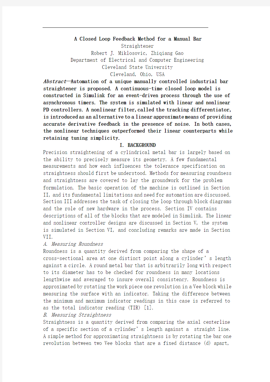
while measuring in the center with an indicator. The distance that the axial centerline of the part deviates from a theoretically straight centerline directly below the indicator equals the extent to which the part is bowed, or warped, over length d. The maximum and minimum indicator readings (IX and IN) are physically represented in Fig.
1. From this, TIR is derived as:
TIR= IX –IN = (R + |Bow|)-(R – |Bow|) =2*|Bow| (1)
Deviations in roundness, outside diameter (OD) size, and finish can adversely affect the measurement.
Figure 1. Max. and min. indicator readings of a bowed part
C. Straightening
The straightening process, which can be broken into steps, simply involves correcting any error while checking for straightness. First, the part is measured for straightness. Then, it is rotated so that the bow is oriented 180 degrees away from the Vee blocks with the maximum indicator reading facing upwards. Finally, a counter-bending force replaces the indicator and straightens the work piece against the Vee blocks.
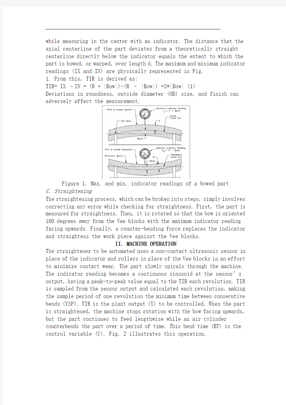
II. MACHINE OPERATION
The straightener to be automated uses a non-contact ultrasonic sensor in place of the indicator and rollers in place of the Vee blocks in an effort to minimize contact wear. The part slowly spirals through the machine. The indicator reading becomes a continuous sinusoid at the sensor’s output, having a peak-to-peak value equal to the TIR each revolution. TIR is sampled from the sensor output and calculated each revolution, making the sample period of one revolution the minimum time between consecutive bends (YSP). TIR is the plant output (Y) to be controlled. When the part is straightened, the machine stops rotation with the bow facing upwards, but the part continues to feed lengthwise while an air cylinder counterbends the part over a period of time. This bend time (BT) is the control variable (U). Fig. 2 illustrates this operation.
Figure 2. The straightener to be automated
A. Process Limitations
There are aspects of the process that can limit the controller’s performance and slow it down by extending YSP. Each is observed and taken into consideration when producing
an accurate simulation model:
1. The ultrasonic sensor introduces RFI noise into its. The use of a feedback filter is essential.
2. A rough part surface finish adds distortion to the sensor output.
3. An out-of-round part superimposes harmonics on the sensor output sinusoid, placing a bound on the minimum steady state error that is achievable.
4. Inconsistent material density produces false measurements. The measured focal length of a
transducer is dependent on the density of the material that is being measured [2]. The unit cannot measure accurately in the presence of a time-variant material density (i.e. hard spots). Although unavoidable, it can be detected, since TIR changes monotonically.
5. An inconsistent OD causes vertical shifts in the sensor output. A differential TIR measurement cancels these affects.
6. A twisted part condition is detected when the angular position of the maximum indicator reading slowly moves with each revolution. This condition is created when the part is not straightened at the precise angular location and occurs because of the quantization affect of the digital readout used by the operator. The new controller will use a continuous signal and the part can be straightened 30 to 45 degrees ahead of the twist when encountered.
B. The Need for Automation
Replacement of the operator with electronic hardware is beneficial in several ways. The cost of the electronics is much less than the ongoing hourly wage and schedule of an operator. The limitations associated with the digital readout are eliminated, which helps the machine to straighten
faster with more precision. The process can be drastically sped up to produce more. Though the minimum sample time is one revolution, it does not need to be slow enough for human comprehension. A Programmable Logic Controller (PLC) can make several calculations and test the result against a set of rules many times faster than a human being.
C. Research Methodology
The focus is split between modeling and control design, since this is a new control problem. The process is manually controlled rather than being strictly manual in operation, meaning the machine needs only a new controller. There is no need for a complete mechanical overhaul, so the best method of straightening is not researched. Typical of a small company, time and money are limited. Gao and Huang [3] presented a new error-based control design framework including such innovations as a nonlinear tracking differentiator and a nonlinear
proportional-integral-derivative (NPID) control method. These methods prove to be powerful and simple to tune, which make them ideal for use in an industrial environment.
III. A CLOSED LOOP SOLUTION
The task of automation can begin once the process is well defined. A straightforward system block diagram is developed, and each block is modeled in Simulink. Aspects of the hardware configuration are carefully considered.
A. From Open Loop to Closed Loop
The open loop multi-input-multi-output (MIMO) block diagram, in Fig. 3, represents the manually controlled process. The operator calculates TIR and monitors the angular position (P) of the bow with each revolution. When Y approaches a specified limit, the operator sets BT proportional to Y and its
rate, and then pushes a button (BP) to straighten the part. The bend timer creates a pulse triggered by BP that counter-bends the part for BT minutes. This event forces the part to have a specific rate for a period of time. After the event, the part takes on a new rate and the process perpetuates. Therefore, Y’ is a
piece-wise continuous function of time. The operator’s involvement in the process is represented as a block in Fig. 4.
Figure 3. Open loop block diagram
Figure 4. Operator block
Rearranging the blocks and breaking each function down into smaller more-manageable blocks reduces the representation to a usable closed loop, single-input-singleoutput (SISO) form. Fig. 5 shows how a SISO plant is obtained by combining the process with the task of sampling the TIR, since it can be consistently computed.
Figure 5. SISO plant block
The plant has a variable-width pulse as the input (U) and the sampled TIR (Y) as the output to be controlled. The incoming changing position of the work piece is modeled as an unknown rate disturbance (D). The closed loop SISO block diagram is shown in Fig. 6.
Figure 6. Closed loop block diagram
B. Hardware Configuration
Depicted in Fig. 7, an encoder and a PLC are the only hardware needed for automation. The encoder feeds the angular position of the part back to the controller, and the PLC handles all of closed loop functions outside of the process.
Figure 7. Hardware configuration
Fig. 8 depicts the hardware layout for plant data acquisition during manual operation. The PLC is also used to calibrate a strip chart recorder, shown in Fig. 9, which simplifies calibration for the operator and removes room for error during data acquisition. Using the PLC for both data acquisition and
control keeps costs lower.
Figure 8. Open loop data acquisition configuration
Figure 9. Chart recorder settings for a .006” TIR signal
IV. MODELING
Simulation modeling involves the construction of Simulink blocks for each of the blocks in the SISO diagram. Three modular blocks are first designed to accommodate the presence
of an event-driven plant in a continuous-time environment where the control variable is an asynchronous pulse width. They are all based on creating asynchronous timers in Simulink
by integrating a constant until it reaches a preset value, then shutting it off by feeding the input with a zero. Equation (2) will reach a value of one in the time interval equal to the average of u(t) over it. The
accuracy increases if the interval is very small or u(t) is a constant function. A suitable difference
equation is given in (3).
A. Triggered Sample-and-Hold (TSH) Block
The output and rate of the plant immediately after the part has been straightened are dependent on BT, and the previous Y and Y’, all of which occur over different time intervals. The function of the TSH block is to sample a value at one point in time so that it can be used at another time. Shown in Fig. 10, the block basically samples the input for a small period of time on the rising edge of an enabling pulse, and then holds that value constant at the output until the block is re-enabled. In Simulink, a constant value can be maintained for an arbitrary period of time by building the output of an integrator to a desired value. A T-second timer is created by integrating 1/T until it equals one. It is used to control the small time interval in (4) which takes a time average of the input.
Figure 10. TSH Simulink block
B. Pulse Block
The bend timer must be able to convert BT from a value into the timed pulse, U. The pulse block, illustrated in Fig. 11, was designed for this purpose. By incorporating (2), it creates a pulse that has a magnitude equal to
the sign of the input and a pulse width equal to the input’s absolute value.
Figure 11. Pulse Simulink block
The heart of the pulse block is the pulse subsystem block, shown in Fig.
12. The reciprocal block generates a divide-byzero error whenever its input is zero. Consequently, the reciprocal block needs to be isolated in a subsystem that is only enabled when supplied with a value that is larger than a user
defined constant.
V. CONTROL DESIGN
There are currently many different control structures available, the simplest of which is the PID controller design. For this reason, a PD controller is first applied to the closed loop model to verify its response and stability. It is used as a benchmark for other controllers. Next, a nonlinear PD (NPD) control scheme is introduced. It retains the tuning ease of the PD controller while improving performance. Last, a nonlinear filter, called the tracking differentiator (TD), is introduced as
an alternate means of providing an accurate derivative feedback to the controller in the presence of noise, thus improving performance.
A. Linear PID Control
For many reasons, PID control is still used in 90% of industrial applications [3]. There are only three tuning parameters, each having direct physical significance to the error signal, not the model. This makes for easy tuning, without having to spend considerable resources on the construction of a linear model. Linear models are often inaccurate and require re-tuning when the real-world plants
they represent are nonlinear and time varying. A control structure that is error-based, and not model-based, is more resilient to model uncertainties [3]. The PID control law in (6) represents the direct physical meanings of the three parameters, where e is the error signal, KP is the proportional gain, KI is the integral gain, and KD is the derivative gain.
K e K edt K P I _ D (6)
VI. SIMULATION
The PD controller and the NPD controller are simulated in Simulink on the
closed loop model. The significance of practical initial conditions and disturbances are considered. Simulation results from the two cases are presented and discussed. Next, the steady state error is compared under various noise and disturbance conditions. Finally, a second order approximation and a TD are implemented in the feedback loop and simulated with heavy feedback noise for both controllers.
A. Transient Performance
Simulating the system and individually adjusting plant parameters to emulate various real world conditions verified the design. Fig. 19 graphs the output and rate response for the PD controller. Notice the control action occurs when the rate is at ±R2 (i.e. ±.001 in this case). The performance measures are defined as follows:
1. The settling time (Ts) is the time it takes for Y to be within ±.001, since this is the general object of
straightening.
2. Overshoot (OS) is the maximum |Y| after it has reached zero.
3. Steady state error (Ess) is the maximum |Y| in the steady state region.The linear and nonlinear PD controllers were tuned to achieve the same Ts. The results of the transient responses of the two controllers for two widely different initial positions are tabulated in Table I, to compare OS and Ess. All units are in thousandths except for settling time.
4. The process can be modeled in discrete time and/or with different software. Writing the entire plant and bend timer in C may simplify the simulation model. From this, a class of problems can be clearly studied.
5. The process can be investigated and modeled as a finite state machine. 调直机的反馈方法
罗伯特·J·Miklosovic,高志强
电气工程和计算机系
克利夫兰州立大学
美国俄亥俄州克利夫兰
手动控制独特自动化的建议。一个连续时间的闭环模型在Simulink中构建事件驱动的过程中,通过使用异步定时器。该系统是模拟线性和非线性PD控制器。非线性滤波器,称为跟踪微分,介绍了作为一个替代的存在噪音,提供准确的微分反馈线性近似手段。在这两种情况下,非线性技术优于线性,同时保留调整简单。一,背景
主要是基于能够精确地测量其几何精度的圆柱形金属条调直。应先了解一些基本的测量和如何每个影响的直线度公差规范。圆度和直线度测量方法覆盖问题制定奠定了基础。本机的基本操作是在第二节,概述,并讨论了其基本的限制和对自动化的需要。第三节讨论通过框图的循环过程中的作用和新的硬件关闭任务。第四节包含所有的块,在Simulink建模描述。在第五节讨论的线性和非线性控制器的设计,该系统是模拟在第六节,第七节总结。
答:测量圆度
圆度是从一个不同点,以及对一个圆圈一个圆柱体的长度比较的横截面积形状的数量。一个圆形的金属条,其直径是任意长有纵向许多地方要检查圆,平均以确
保整体一致性。圆度近似V型块在旋转工件革命的一个指标,同时测量表面。在这种情况下的最低和最高指示读数之间的差异被称为总读数(TIR)[1]。
B.测量直线度
直线是比较一个圆柱体的长度对直线的一个特定部分的轴向中心线派生的数量。一个简单的方法是近似直线旋转酒吧之间,是一个固定的距离(四)除V型块革命,而在测量指标的中心。的一部分的轴向中心线偏离的指标低于直接从理论上直中心线的距离等于其中部分是鞠躬,或扭曲的程度,超过长度d。身体的最高和最低的指标读数(九中)代表图。
外径(OD值)的大小,圆度偏差,并完成产生不利影响测量结果。
一个弓形部分的指标读数
在整顿过程中,它可以分解成步骤,只涉及纠正任何错误,同时检查直线。首先,部分的直线度测量。然后,它是旋转,以便弓是面向180度的V型块朝上最大的指标读数。最后,反弯曲力的替代指标,并拉直对V型块的工件。
二、机器操作
矫直机是自动化,在地方指标和地方努力的V型块辊使用一种非接触式超声波传感器,以尽量减少接触磨损。部分慢慢地通过机器螺旋。该指标读数在传感器的输出连续正弦波,有等于每个革命的TIR的峰 - 峰值。公路运输从传感器输出进行采样,并计算出每个革命,做一个革命的样本期间连续弯(YSP)之间的最短时间。公路运输是厂输出(Y)进行控制。部分拉直,当机器停止与弓朝上旋转,但部分继续养活纵向气缸counterbends过了一段时间的一部分。这弯曲的时间(BT)是控制变量(美)。图2说明了这种操作。
A.工艺限制
有方面的过程中,可以限制控制器的性能和扩大永信药品减缓下来。每个观察和考虑生产
精确的仿真模型:
1、超声波传感器引入到其RFI噪声。反馈滤波器的使用是必不可少的。
2、一个粗糙的零件表面光洁度增加了传感器输出的失真。
3、一个地地道道的圆形部分叠加在传感器输出正弦波的谐波,放置一个最低的稳态误差是可以实现的约束。
4、材料的密度不一致产生虚假的测量。一个测得的焦距
传感器是依赖于正在测量[2]材料的密度。本机无法准确测量中存在的时间变材料的密度(即硬点)。虽然不可避免的,它可以检测到,因为运输单调变化。
5、不一致的外径导致传感器输出的垂直变化。一个差的TIR测量抵消这些影响。
6、一个扭曲的部分条件被检测到时最大的指标读数的角位置慢慢移动每个革命。这种情况下被创建时的精确角位置拉直的部分不发生由运营商所使用的数字读数,因为量化的影响。新的控制器将使用一个连续信号,并提前30至45度的扭转时遇到的一部分可以被拉直。
B.自动化的必要性
更换运营商与电子硬件在几个方面是有利的。电子产品的成本是远远高于目前的每小时工资和操作员的时间表。数字读数相关的限制被取消,这有助于机器更快更精确整顿。这个过程可以被大大加快生产更多。虽然最小的采样时间是一个革命,它不需要是缓慢的,对人类的理解不够。可编程逻辑控制器(PLC),可以使一些计算和一套规则,对测试结果比人类快很多倍。
C.研究方法论
分裂之间的建模和控制设计的重点,因为这是一个新的控制问题。手动控制的过程,而不是严格的操作手册,这意味着机,只需要一个新的控制器。有没有必要为一个完整的机械检修,所以最好的方法是不整顿研究。典型的一家小公司,有限的时间和金钱。高和黄[3]提出了一个新的基于错误控制设计框架,包括非线性跟踪微分器和非线性比例 - 积分 - 微分(非线性PID)控制方法等创新。这些方法被证明是强大的和简单的曲调,使它们在工业环境中使用的理想选择。第三。闭环解决方案
一旦这个过程被很好地定义,自动化的任务就可以开始。开发一个简单的系统框图,每块在Simulink建模。硬件配置方面慎重考虑。
答:从开环到闭环
开环多输入多输出(MIMO)的框图,如图。 3,代表手动控制的过程。操作计算的TIR和监控每个革命弓的角位置。当Y接近指定的限制,操作员设置BT的比例为Y然后按下一个按钮(BP)的整顿部分。弯曲定时器创建的BP触发脉冲,这一事件迫使一部分有一段时间的具体税率。活动结束后,部分需要一个新的速度和进程延续。因此,Y“是一个分段连续函数的时间。在这个过程中运营商的参与,是块图作为代表。
图3、开环框图
图4、算块
算块和每个功能分解成更小,更易于管理的块降低到一个可用的闭环,单输入,singleoutput(SISO)的形式表示。图5 SISO植物如何获得采样的TIR的任务相结合的过程中,因为它可以持续计算图
单输入单输出植物块
拥有厂房作为输入(U)和要控制的输出采样的TIR(Y)的可变宽度的脉冲。传入改变工件的位置是仿照干扰(四)作为一个未知的利率。闭环SISO框图如图。
6、闭环框图
7、编码器和PLC是唯一的自动化所需的硬件。编码器反馈的角位置的一部分返回给控制器,PLC的处理进程之外的所有闭环功能。
图7。硬件配置
图8描绘了在手工操作的工厂数据采集的硬件布局。 PLC也被用来校准条状图表记录,如图。 9、简化操作的校准和消除数据采集过程中的错误空间。为数据采集使用PLC和控制使成本更低。图8开环数据采集配置图9图表记录设置为.006“的TIR信号
四。建模
仿真建模涉及的Simulink模块的建设,为每个块在SISO图。第一,三个模块化块设计,以适应存在
在连续时间的环境下控制变量是一个异步脉冲宽度的事件驱动的植物。它们都是基于建立在Simulink的异步定时器
通过整合不断,直到它到达一个预设值,然后关闭它喂养零输入。方程(2)将到达的时间间隔等于平均的U(T)的值。如果是非常小的时间间隔的准确性增加或U(T)是一个常数函数。一个合适的区别
A.触发采样和保持(TSH)的座
工厂的产量和部分已被拉直后,立即率对BT的依赖,和前面的Y和Y',所有这些都发生在不同的时间间隔。的TSH块的功能是在一个时间点采样值,因此,它可以在其他时间使用。如图。 10块基本样本的一个小的时间内对一个有利的脉冲
上升沿输入,然后认为值恒定的输出,直到块被重新启用。在Simulink中,保持一个恒定的值可以为任意时间内,通过建立一个集成的输出所需的值。创建相结合,直到它等于1 / T的T-秒计时器。它是用来控制(4)小的时间间隔,需要输入的时间平均。
弯曲计时器必须能够从一个值转换成定时脉冲,U.脉冲块,在图BT。 11,是专为这个目的。通过合并(2),它创建了一个有一个大小相等符号的输入和输入的绝对值等于脉冲宽度的脉冲。
图11。脉冲Simulink块
脉冲块的核心是脉冲子系统块,如图所示。 12。倒数块生成隔膜,byzero错误时,其输入是零。因此需要在一个仅启用时的值是大于用户提供的子系统分离相互块。
五,控制设计
目前有许多不同的控制结构,其中最简单的是PID控制器的设计。出于这个原因,PD控制器首先采用闭环模型,以验证其响应和稳定性。它是用来作为一个基准,其他控制器。接下来,介绍了一种非线性PD(NPD)的管制计划。它保留了调整PD控制器易用性,同时提高性能。最后,非线性滤波,称为跟踪微分器(TD),介绍了作为
提供一个准确的微分反馈控制器中存在的噪声,从而提高了性能的替代手段。A.线性PID控制
.0原因是多方面的,仍然采用PID控制在90%的工业应用[3]。有只有三个调整参数,每个有直接的物理意义的错误信号,不是模型。这使得容易调整,而不必花相当多的资源,建造一个线性模型。线性模型往往是不准确的,并要求重新调整时,现实世界中的植物
他们表示,非线性和时变。控制结构是基于错误,而不是基于模型,更有弹性模型的不确定性[3]。 PID控制法(6)代表三个参数,其中e是错误的信号直接的物理意义,KP为比例增益,KI为积分增益,KD是微分增益。
六。模拟
PD控制器和NPD的控制器都在Simulink模拟闭环模型。被认为是实际的初始条件和干扰的意义。提出并讨论了两种情况下的模拟结果。下一步,稳态误差的各种噪声和干扰条件下相比。最后,二阶近似和TD在反馈环路和两个控制器沉重的反馈噪声模拟实施。
A.瞬态性能
模拟系统和个别调整工厂参数,以模拟各种现实世界中验证了设计的条件。图19图PD控制器的输出和速度响应。请注意控制动作发生率在±R2是在这种情况下(即±0.001)。性能措施的定义如下:
1。建立时间(TS)是为Y在±.001所花费的时间,因为这是一般的对象
整顿。
2。过冲(OS)是最大| Y |后已达到零。
3。稳态误差(ESS)是最大| Y |在稳态region.The线性和非线性PD控制器进行调整,以达到相同的TS。两个迥然不同的初始位置的两个控制器的瞬态响应的结果列于表一,比较OS和ESS。所有单位都在千分之解决时间除外。
4。在离散的时间和/或不同的软件可以模拟这个过程。写在C整个工厂和弯曲定时器可以简化仿真模型。由此看来,一类问题,可以清楚地研究。
5。这个过程可以进行调查,并作为一个有限状态机建模。
外文翻译 英文原文 Belt Conveying Systems Development of driving system Among the methods of material conveying employed,belt conveyors play a very important part in the reliable carrying of material over long distances at competitive cost.Conveyor systems have become larger and more complex and drive systems have also been going through a process of evolution and will continue to do so.Nowadays,bigger belts require more power and have brought the need for larger individual drives as well as multiple drives such as 3 drives of 750 kW for one belt(this is the case for the conveyor drives in Chengzhuang Mine).The ability to control drive acceleration torque is critical to belt conveyors’performance.An efficient drive system should be able to provide smooth,soft starts while maintaining belt tensions within the specified safe limits.For load sharing on multiple drives.torque and speed control are also important considerations in the drive system’s design. Due to the advances in conveyor drive control technology,at present many more reliable.Cost-effective and performance-driven conveyor drive systems covering a wide range of power are available for customers’ choices[1]. 1 Analysis on conveyor drive technologies 1.1 Direct drives Full-voltage starters.With a full-voltage starter design,the conveyor head shaft is direct-coupled to the motor through the gear drive.Direct full-voltage starters are adequate for relatively low-power, simple-profile conveyors.With direct fu11-voltage starters.no control is provided for various conveyor loads and.depending on the ratio between fu11-and no-1oad power requirements,empty starting times can be three or four times faster than full load.The maintenance-free starting system is simple,low-cost and very reliable.However, they cannot control starting torque and maximum stall torque;therefore.they are
毕业论文(设计) 外文翻译 题目:机械加工介绍
机械加工介绍 1.车床 车床主要是为了进行车外圆、车端面和镗孔等项工作而设计的机床。车削很少在其他种类的机床上进行,而且任何一种其他机床都不能像车床那样方便地进行车削加工。由于车床还可以用来钻孔和铰孔,车床的多功能性可以使工件在一次安装中完成几种加工。因此,在生产中使用的各种车床比任何其他种类的机床都多。 车床的基本部件有:床身、主轴箱组件、尾座组件、溜板组件、丝杠和光杠。 床身是车床的基础件。它能常是由经过充分正火或时效处理的灰铸铁或者球墨铁制成。它是一个坚固的刚性框架,所有其他基本部件都安装在床身上。通常在床身上有内外两组平行的导轨。有些制造厂对全部四条导轨都采用导轨尖朝上的三角形导轨(即山形导轨),而有的制造厂则在一组中或者两组中都采用一个三角形导轨和一个矩形导轨。导轨要经过精密加工以保证其直线度精度。为了抵抗磨损和擦伤,大多数现代机床的导轨是经过表面淬硬的,但是在操作时还应该小心,以避免损伤导轨。导轨上的任何误差,常常意味着整个机床的精度遭到破坏。 主轴箱安装在内侧导轨的固定位置上,一般在床身的左端。它提供动力,并可使工件在各种速度下回转。它基本上由一个安装在精密轴承中的空心主轴和一系列变速齿轮(类似于卡车变速箱)所组成。通过变速齿轮,主轴可以在许多种转速下旋转。大多数车床有8~12种转速,一般按等比级数排列。而且在现代机床上只需扳动2~4个手柄,就能得到全部转速。一种正在不断增长的趋势是通过电气的或者机械的装置进行无级变速。 由于机床的精度在很大程度上取决于主轴,因此,主轴的结构尺寸较大,通常安装在预紧后的重型圆锥滚子轴承或球轴承中。主轴中有一个贯穿全长的通孔,长棒料可以通过该孔送料。主轴孔的大小是车床的一个重要尺寸,因此当工件必须通过主轴孔供料时,它确定了能够加工的棒料毛坯的最大尺寸。 尾座组件主要由三部分组成。底板与床身的内侧导轨配合,并可以在导轨上作纵向移动。底板上有一个可以使整个尾座组件夹紧在任意位置上的装置。尾座体安装在底板上,可以沿某种类型的键槽在底板上横向移动,使尾座能与主轴箱中的主轴对正。尾座的第三个组成部分是尾座套筒。它是一个直径通常大约在51~76mm之间的钢制空心圆柱体。
ZigBee:无线技术,低功耗传感器网络 加里莱格 美国东部时间2004年5月6日上午12:00 技师(工程师)们在发掘无线传感器的潜在应用方面从未感到任何困难。例如,在家庭安全系统方面,无线传感器相对于有线传感器更易安装。而在有线传感器的装置通常占无线传感器安装的费用80%的工业环境方面同样正确(适用)。而且相比于有线传感器的不切实际甚至是不肯能而言,无线传感器更具应用性。虽然,无线传感器需要消耗更多能量,也就是说所需电池的数量会随之增加或改变过于频繁。再加上对无线传感器由空气传送的数据可靠性的怀疑论,所以无线传感器看起来并不是那么吸引人。 一个低功率无线技术被称为ZigBee,它是无线传感器方程重写,但是。一个安全的网络技术,对最近通过的IEEE 802.15.4无线标准(图1)的顶部游戏机,ZigBee的承诺,把无线传感器的一切从工厂自动化系统到家庭安全系统,消费电子产品。与802.15.4的合作下,ZigBee提供具有电池寿命可比普通小型电池的长几年。ZigBee设备预计也便宜,有人估计销售价格最终不到3美元每节点,。由于价格低,他们应该是一个自然适应于在光线如无线交换机,无线自动调温器,烟雾探测器和家用产品。 (图1)
虽然还没有正式的规范的ZigBee存在(由ZigBee联盟是一个贸易集团,批准应该在今年年底),但ZigBee的前景似乎一片光明。技术研究公司 In-Stat/MDR在它所谓的“谨慎进取”的预测中预测,802.15.4节点和芯片销售将从今天基本上为零,增加到2010年的165万台。不是所有这些单位都将与ZigBee结合,但大多数可能会。世界研究公司预测的到2010年射频模块无线传感器出货量4.65亿美量,其中77%是ZigBee的相关。 从某种意义上说,ZigBee的光明前途在很大程度上是由于其较低的数据速率20 kbps到250 kbps的,用于取决于频段频率(图2),比标称1 Mbps的蓝牙和54的802.11g Mbps的Wi - Fi的技术。但ZigBee的不能发送电子邮件和大型文件,如Wi - Fi功能,或文件和音频,蓝牙一样。对于发送传感器的读数,这是典型的数万字节数,高带宽是没有必要,ZigBee的低带宽有助于它实现其目标和鲁棒性的低功耗,低成本。 由于ZigBee应用的是低带宽要求,ZigBee节点大部分时间可以睡眠模式,从而节省电池电源,然后醒来,快速发送数据,回去睡眠模式。而且,由于ZigBee 可以从睡眠模式过渡到15毫秒或更少主动模式下,即使是睡眠节点也可以达到适当的低延迟。有人扳动支持ZigBee的无线光开关,例如,将不会是一个唤醒延迟知道前灯亮起。与此相反,支持蓝牙唤醒延迟通常大约三秒钟。 一个ZigBee的功耗节省很大一部分来自802.15.4无线电技术,它本身是为低功耗设计的。 802.15.4采用DSSS(直接序列扩频)技术,例如,因为(跳频扩频)另类医疗及社会科学院将在保持一样使用它的频率过大的权力同步。 ZigBee节点,使用802.15.4,是几个不同的沟通方式之一,然而,某些方面比别人拥有更多的使用权力。因此,ZigBee的用户不一定能够实现传感器网络上的任何方式选择和他们仍然期望多年的电池寿命是ZigBee的标志。事实
Mechanical engineering 1.The porfile of mechanical engineering Engingeering is a branch of mechanical engineerig,it studies mechanical and power generation especially power and movement. 2.The history of mechanical engineering 18th century later periods,the steam engine invention has provided a main power fountainhead for the industrial revolution,enormously impelled each kind of mechznicalbiting.Thus,an important branch of a new Engineering –separated from the civil engineering tools and machines on the branch-developed together with Birmingham and the establishment of the Associantion of Mechanical Engineers in 1847 had been officially recognized.The mechanical engineering already mainly used in by trial and error method mechanic application technological development into professional engineer the scientific method of which in the research,the design and the realm of production used .From the most broad perspective,thedemend continuously to enhance the efficiencey of mechanical engineers improve the quality of work,and asked him to accept the history of the high degree
Lathes Lathes are machine tools designed primarily to do turning, facing and boring, Very little turning is done on other types of machine tools, and none can do it with equal facility. Because lathes also can do drilling and reaming, their versatility permits several operations to be done with a single setup of the work piece. Consequently, more lathes of various types are used in manufacturing than any other machine tool. The essential components of a lathe are the bed, headstock assembly, tailstock assembly, and the leads crew and feed rod. The bed is the backbone of a lathe. It usually is made of well normalized or aged gray or nodular cast iron and provides s heavy, rigid frame on which all the other basic components are mounted. Two sets of parallel, longitudinal ways, inner and outer, are contained on the bed, usually on the upper side. Some makers use an inverted V-shape for all four ways, whereas others utilize one inverted V and one flat way in one or both sets, They are precision-machined to assure accuracy of alignment. On most modern lathes the way are surface-hardened to resist wear and abrasion, but precaution should be taken in operating a lathe to assure that the ways are not damaged. Any inaccuracy in them usually means that the accuracy of the entire lathe is destroyed. The headstock is mounted in a foxed position on the inner ways, usually at the left end of the bed. It provides a powered means of rotating the word at various speeds . Essentially, it consists of a hollow spindle, mounted in accurate bearings, and a set of transmission gears-similar to a truck transmission—through which the spindle can be rotated at a number of speeds. Most lathes provide from 8 to 18 speeds, usually in a geometric ratio, and on modern lathes all the speeds can be obtained merely by moving from two to four levers. An increasing trend is to provide a continuously variable speed range through electrical or mechanical drives. Because the accuracy of a lathe is greatly dependent on the spindle, it is of heavy construction and mounted in heavy bearings, usually preloaded tapered roller or ball types. The spindle has a hole extending through its length, through which long bar stock can be fed. The size of maximum size of bar stock that can be machined when the material must be fed through spindle. The tailsticd assembly consists, essentially, of three parts. A lower casting fits on the inner ways of the bed and can slide longitudinally thereon, with a means for clamping the entire assembly in any desired location, An upper casting fits on the lower one and can be moved transversely upon it, on some type of keyed ways, to permit aligning the assembly is the tailstock quill. This is a hollow steel cylinder, usually about 51 to 76mm(2to 3 inches) in diameter, that can be moved several inches longitudinally in and out of the upper casting by means of a hand wheel and screw. The size of a lathe is designated by two dimensions. The first is known as the swing. This is the maximum diameter of work that can be rotated on a lathe. It is approximately twice the distance between the line connecting the lathe centers and the nearest point on the ways, The second size dimension is the maximum distance between centers. The swing thus indicates the maximum work piece diameter that can be turned in the lathe, while the distance between centers indicates the maximum length of work piece that can be mounted between centers. Engine lathes are the type most frequently used in manufacturing. They are heavy-duty machine tools with all the components described previously and have power drive for all tool movements except on the compound rest. They commonly range in size from 305 to 610 mm(12 to 24 inches)swing and from 610 to 1219 mm(24 to 48 inches) center distances, but swings up to 1270 mm(50 inches) and center distances up
普通钻床改造为多轴钻床 目前,我国中、小型企业的产品质量和生产效率都需要有一个新的提高, 但是加工手段却远远不能满足需要, 许多中小型企业都结合自己的实际对设备的技术状态进行改进,通过强化自身, 以求自我发展普通钻床为单轴机床,但安装上多轴箱就会成为多轴的钻床,改造成多轴钻床后,能大大地缩短加工时间,提高生产效率。 多轴加工应用:据统计,一般在车间中普通机床的平均切削时间很少超过全部工作时间的15%。其余时间是看图、装卸工件、调换刀具、操作机床、测量以及清除铁屑等等。使用 数控机床虽然能提高85%,但购置费用大。某些情况下,即使生产率高,但加工相同的零件,其成本不一定比普通机床低。故必须更多地缩短加工时间。不同的加工方法有不同的特点,就钻削加工而言,多轴加工是一种通过少量投资来提高生产率的有效措施。 多轴加工优势:虽然不可调式多轴头在自动线中早有应用,但只局限于大批量生产。即使采用可调式多轴头扩大了使用范围,仍然远不能满足批量小、孔型复杂的要求。尤其随着工业的发展,大型复杂的多轴加工更是引人注目。例如原子能发电站中大型冷凝器水冷壁管板有15000个“ 20孔,若以摇臂钻床加工,单单钻孔与锪沉头孔就要842.5小时,另外还要 划线工时151.1 小时。但若以数控八轴落地钻床加工,钻锪孔只要171.6 小时,划线也简单,只要1.9 小时。因此,利用数控控制的二个坐标轴,使刀具正确地对准加工位置,结合多轴加工不但可以扩大加工范围,而且在提高精度的基础上还能大大地提高工效,迅速地制造出原来不易加工的零件。有人分析大型高速柴油机30 种箱形与杆形零件的2000 多个钻孔操作中,有40%可以在自动更换主轴箱机床中用二轴、三轴或四轴多轴头加工,平均可减少20%的加工时间。1975年法国巴黎机床展览会也反映了多轴加工的使用愈来愈多这一趋势。 多轴加工的设备:多轴加工是在一次进给中同时加工许多孔或同时在许多相同或不同工件上各加工一个
AVI 影音文件Audio Video Interleaved 声音图象交叉存取。AVI是一种微软媒体文件格式,类似于MPEG和QuickTime。在AVI中,声音和图象是交叉的存取在一个文件中的每个段的。 ADSL 非对称数字用户线路 非对称数字用户线路。这种DSL叫做非对称DSL,将成为广大家庭和小型商业客户最熟悉的一种DSL。ADSL之所以叫做非对称是因为它的两个双工通道都用来向用户传输数据。仅有很小一部分带宽用来回送用户的信息。然而,大部Internet 特别是富于图形和多媒体Web 数据需要很大的下传带宽,同时用户信息相对比较少,上传的带宽也不要很大。使用ADSL时,下传的速率可以达到6.1 Mbps,而上传速率也可以达到640 Kbps。高的下传速率意味着您的电话可以传输动画,声音和立体图形。另外,一小部分的带宽可以用来传输语音信号,您可以同时打电话而不用再使用第二条电话线。不象电视线路提供的相同的服务,使用ADSL,您不需要和您的邻居争用带宽。有时候,现有的电话线可以使用ADSL,而有时候却要升级,除非电话公司提供了无分离器的ADSL,您就必须安装一个DSL调制解调器。 ASP (Application Services Provider) 应用服务提供商 是指配置、租赁、管理应用解决方案,它是随着外包趋势、软件应用服务和相关业务的发展而逐渐形成的。ASP具有三大特点:首先,ASP向用户提供的服务应用系统本身的所有权属ASP,用户租用服务之后对应用系统拥有使用权;并且,应用系统被集中放置在ASP的IDC(Internet数据服务中心)中,具有充足的带宽、电力和空间保证以及具有专业质量的系统维护服务;ASP定期向用户收取服务费。应用服务提供商将以全新的方式推动应用服务产业的巨大发展。ATM (Asynchronous Transmission Mode) 异步传输模式 这是为满足宽带综合业务数据通信,在分组交换技术的基础上迅速发展起来的通信新技术。可以实现语音、数据、图像、视频等信号的高速传输。 AI (Artificial Intelligent) 人工智能 是计算机科学的一门研究领域。它试图赋予计算机以人类智慧的某些特点,用计算机来模拟人的推理、记忆、学习、创造等智能特征,主要方法是依靠有关知识进行逻辑推理,特别是利用经验性知识对不完全确定的事实进行的精确性推理。 AD 网上广告 指一则按规定象素尺寸或字节数设定的标语或图像,通常是以动画表现的。 Baseband 基带 在该方式中,电压脉冲直接加到电缆,并且使用电缆的整个信号频率范围。基带与宽带传输相比较,宽带传输中,来自多条信道的无线信号调制到不同的“载波”频率上,带宽被划分为不同信道,每信道上的频率范围一定。LocalTalk及以太网都是基带网络,一次仅传输一个信号,电缆上信号电平的改变表示数字值0或者1。使用电缆的整个带宽建立起两个系统间的通信对话,然后两个系统轮流传送。在此期间,共享电缆的其它系统不能传送。基带传输系统中的直流信号往往由于电阻、电容等因素而衰减。另外马达、荧光灯等电子设备产生的外部电磁干扰也会加快信号的衰减。传输率越高,信号就越容易被衰减。为此,以太网等建网标准规定了网络电缆类型、电缆屏蔽、电缆距离、传输率以及在大部分环境中提供相对无差错服务的有关细节。 BBS (Bulletin Board System) 电子公告板 这是因特网提供的一种信息服务,为用户提供一个公用环境,以使寄存函件,读取通告,参与讨论和交流信息。Bluetooth 蓝牙(一种无线通信的标准) 蓝牙技术涉及一系列软硬件技术、方法和理论,包括:无线通信与网络技术,软件工程、软件可靠性理论,协议的正确性验证、形式化描述和一致性与互联测试技术,嵌入式实时操作系统(Embedded RTOS),跨平台开发和用户界面图形化技术,软/硬件接口技术(如RS232,UART,USB等),高集成、低功耗芯片技术等。蓝牙的目标是要提供一种通用的无线接口标准,用微波取代传统网络中错综复杂的电缆,在蓝牙设备间实现方便快捷、灵活安全、低成本低功耗的数据和话音通信。因此,其载频选用在全球都可用的2.45GHz ISM(工业、科学、医学)频带。 CA (Certificate Authority)认证中心 是在线交易的监督者和担保人,主要进行电子证书管理、电子贸易伙伴关系建立和确认、密钥管理、为支付系统中的各参与方提供身份认证等。CA类似于现实生活中公证人的角色,具有权威性,是一个普遍可信的第三方。
机械类外文翻译 塑料注塑模具浇口优化 摘要:用单注塑模具浇口位置的优化方法,本文论述。该闸门优化设计的目的是最大限度地减少注塑件翘曲变形,翘曲,是因为对大多数注塑成型质量问题的关键,而这是受了很大的部分浇口位置。特征翘曲定义为最大位移的功能表面到表面的特征描述零件翘曲预测长度比。结合的优化与数值模拟技术,以找出最佳浇口位置,其中模拟armealing算法用于搜索最优。最后,通过实例讨论的文件,它可以得出结论,该方法是有效的。 注塑模具、浇口位臵、优化、特征翘曲变形关键词: 简介 塑料注射成型是一种广泛使用的,但非常复杂的生产的塑料产品,尤其是具有高生产的要求,严密性,以及大量的各种复杂形状的有效方法。质量ofinjection 成型零件是塑料材料,零件几何形状,模具结构和工艺条件的函数。注塑模具的一个最重要的部分主要是以下三个组件集:蛀牙,盖茨和亚军,和冷却系统。拉米夫定、Seow(2000)、金和拉米夫定(2002) 通过改变部分的尼斯达到平衡的腔壁厚度。在平衡型腔充填过程提供了一种均匀分布压力和透射电镜,可以极大地减少高温的翘曲变形的部分~但仅仅是腔平衡的一个重要影响因素的一部分。cially Espe,部分有其功能上的要求,其厚度通常不应该变化。 pointview注塑模具设计的重点是一门的大小和位臵,以及流道系统的大小和布局。大门的大小和转轮布局通常被认定为常量。相对而言,浇口位臵与水口大小布局也更加灵活,可以根据不同的零件的质量。 李和吉姆(姚开屏,1996a)称利用优化流道和尺寸来平衡多流道系统为multiple 注射系统。转轮平衡被形容为入口压力的差异为一多型腔模具用相同的蛀牙,也存
毕业设计(论文)外文资料翻译 系部: 专业: 姓名: 学号: 外文出处:English For Electromechanical (用外文写) Engineering 附件:1.外文资料翻译译文;2.外文原文。 指导教师评语: 此翻译文章简单介绍了各机床的加工原理,并详细介绍了各机床的构造,并对方各机床的加工方法法进行了详细的描述, 翻译用词比较准确,文笔也较为通顺,为在以后工作中接触英 文资料打下了基础。 签名: 年月日注:请将该封面与附件装订成册。
附件1:外文资料翻译译文 机床 机床是用于切削金属的机器。工业上使用的机床要数车床、钻床和铣床最为重要。其它类型的金属切削机床在金属切削加工方面不及这三种机床应用广泛。 车床通常被称为所有类型机床的始祖。为了进行车削,当工件旋转经过刀具时,车床用一把单刃刀具切除金属。用车削可以加工各种圆柱型的工件,如:轴、齿轮坯、皮带轮和丝杠轴。镗削加工可以用来扩大和精加工定位精度很高的孔。 钻削是由旋转的钻头完成的。大多数金属的钻削由麻花钻来完成。用来进行钻削加工的机床称为钻床。铰孔和攻螺纹也归类为钻削过程。铰孔是从已经钻好的孔上再切除少量的金属。 攻螺纹是在内孔上加工出螺纹,以使螺钉或螺栓旋进孔内。 铣削由旋转的、多切削刃的铣刀来完成。铣刀有多种类型和尺寸。有些铣刀只有两个切削刃,而有些则有多达三十或更多的切削刃。铣刀根据使用的刀具不同能加工平面、斜面、沟槽、齿轮轮齿和其它外形轮廓。 牛头刨床和龙门刨床用单刃刀具来加工平面。用牛头刨床进行加工时,刀具在机床上往复运动,而工件朝向刀具自动进给。在用龙门刨床进行加工时,工件安装在工作台上,工作台往复经过刀具而切除金属。工作台每完成一个行程刀具自动向工件进给一个小的进给量。 磨削利用磨粒来完成切削工作。根据加工要求,磨削可分为精密磨削和非精密磨削。精密磨削用于公差小和非常光洁的表面,非精密磨削用于在精度要求不高的地方切除多余的金属。 车床 车床是用来从圆形工件表面切除金属的机床,工件安装在车床的两个顶尖之间,并绕顶尖轴线旋转。车削工件时,车刀沿着工件的旋转轴线平行移动或与工件的旋转轴线成一斜角移动,将工件表面的金属切除。车刀的这种位移称为进给。车
附录1 中文名称:机械加工中心英文名称:machining center 其他名称:自动换刀数控机床 定义:能自动更换工具,对一次装夹的工件进行多工序加工的数控机床。机械加工中心,简称cnc,是由机械设备与数控系统组成的使用于加工复杂形状工件的高效率自动化机床。加工中心又叫电脑锣。加工中心备有刀库,具有自动换刀功能,是对工件一次装夹后进行多工序加工的数控机床。加工中心是高度机电一体化的产品,工件装夹后,数控系统能控制机床按不同工序自动选择、更换刀具、自动对刀、自动改变主轴转速、进给量等,可连续完成钻、镗、铣、铰、攻丝等多种工序,因而大大减少了工件装夹时间、测量和机床调整等辅助工序时间,对加工形状比较复杂,精度要求较高,品种更换频繁的零件具有良好的经济效果。按控制轴数可分为:(1)三轴加工中心 (2)四轴加工中心 (3)五轴加工中心。 项目二机械加工中心设备技术分类加工中心的品种、规格较多,这里仅从结构上对其作一分类。 一、立式加工中心指主轴轴线为垂直状态设置的加工中心。其结构形式多为固定立柱式,工作台为长方形,无分度回转功能,适合加工盘、套、板类零件。一般具有三个直线运动坐标,并可在工作台上安装一个水平轴的数控回转台,用以加工螺旋线零件。立式加工中心装夹工件方便,便于操作,易于观察加工情况,但加工时切屑不易排除,且受立柱高度和换刀装置的限制,不能加工太高的零件。立式加工中心的结构简单,占地面积小,价格相对较低,应用广泛。 二、卧式加工中心指主轴轴线为水平状态设置的加工中心。通常都带有可进行分度回转运动的工作台。卧式加工中心一般都具有三个至五个运动坐标,常见的是三个直线运动坐标加一个回转运动坐标,它能够使工件在一次装夹后完成除安装面和顶面以外的其余四个面的加工,最适合加工箱体类零件。卧式加工中心调试程序及试切时不便观察,加工时不便监视,零件装夹和测量不方便,但加工时排屑容易,对加工有利。与立式加工中心相比,卧式加工中心的结构复杂,占地面积大,价格也较高。
【附录】 英文文献 The Application of one point Multiple Access Spread Spectrum Communication System Liu Jiangang, Nanyang City, HenanProvince Electric Power Industry Bureau 【ABSTRACT】Spread Spectrum Digital Microwave communication as a communication, because their excellent performance have been widely used. The article in Nanyang City Power Industry Bureau one point Multiple Access Spread Spectrum Communication System as an example.briefed the spread spectrum communications, the basic concept and characteristics of the power system communication applications .KEYWORDS:one point multiple access; Spread-spectrum communication; Attenuation Nanyang City in the outskirts of Central cloth 35 to 11 kv substation farm terminals, their operation management rights belong to the Council East, Rural Power Company west (the eastern suburb of agricultural management companies -- four, the western suburbs of Rural Power Company Management 7), Scheduling of the various stations of the means of communication to the original M-150 radio and telephone posts. 2002 With the transformation of rural network, the remote station equipment into operation and communication channels to put a higher demand .As PUC Dispatch Communication Building to the east and west of farmers -- the difference between a company linked to fiber, Therefore, if 11 substations and the establishment of a transfer Link Building links Point may be the data and voice were sent to two rural power companies dispatch room, Rural Network scheduling for the implementation of automation to create the necessary conditions. Given the status and power grid substation level, nature, taking into account the carrier and optical-fiber communications to conduct multiple forwarding, increasing the instability factor, considering the cost and conditions of the urban construction, Finally decided to adopt wireless spread-spectrum technology to establish that 11
机械工业出版社2004年3月第1版 20.9 MACHINABILITY The machinability of a material usually defined in terms of four factors: 1、Surface finish and integrity of the machined part; 2、Tool life obtained; 3、Force and power requirements; 4、Chip control. Thus, good machinability good surface finish and integrity, long tool life, and low force And power requirements. As for chip control, long and thin (stringy) cured chips, if not broken up, can severely interfere with the cutting operation by becoming entangled in the cutting zone. Because of the complex nature of cutting operations, it is difficult to establish relationships that quantitatively define the machinability of a material. In manufacturing plants, tool life and surface roughness are generally considered to be the most important factors in machinability. Although not used much any more, approximate machinability ratings are available in the example below. 20.9.1 Machinability Of Steels Because steels are among the most important engineering materials (as noted in Chapter 5), their machinability has been studied extensively. The machinability of steels has been mainly improved by adding lead and sulfur to obtain so-called free-machining steels. Resulfurized and Rephosphorized steels. Sulfur in steels forms manganese sulfide inclusions (second-phase particles), which act as stress raisers in the primary shear zone. As a result, the chips produced break up easily and are small; this improves machinability. The size, shape, distribution, and concentration of these inclusions significantly influence machinability. Elements such as tellurium and selenium, which are both chemically similar to sulfur, act as inclusion modifiers in resulfurized steels. Phosphorus in steels has two major effects. It strengthens the ferrite, causing