附录A 译文
随车液压起重机的控制
摘要:本文主要是描述随车液压起重机的控制过程。这篇论文分为五个部分:需求分析,液压系统以及存在的问题的分析,不同结构产生不同问题的分析,基于更加先进复杂电液比例控制阀的新技术的发展趋势的分析。本文的研究工作是和实际的工业相结合的,比纯粹的研究理论更有意义。
关键字:随车液压起重机,控制策略,电液比例控制阀
1.引言
本文主要叙述的是对随车起重机控制系统的改进方法
随车汽车起重机可以看成是一种大型柔性控制机械结构。这种控制系统把操作人员的命令由机械结构变为执行动作。
这样定义这种控制系统是为了避免在设计它事产生模糊的思想这是一种通过人的命令把能量转化成机械动作的控制系统。本文所写的就是这种控制系统。以这个目标为指导方针来分析怎样设计出新的控制系统。
文章分为五个部分:
1.分析这种控制系统必须据有易操作性,高强度,高效性,稳定性,安全性。
2.分析目前这种操作系统所存在的问题。
3.从不同的方面分析这种控制系统:不同的操作方式,不同的控制方法,不
同的组织结构。
4.介绍一种适合于未来工业的比较经济的新的控制系统。
5.分析一种据有高性能,高效率,易控制等的比较好的控制系统。它将成为
今后研究的比较经济高效的一种方案。
2. 论文部分
2.1 对控制系统必备条件的分析
在一种新的操作系统开始正式投入工作之前,对这种控制系统据有严格的要求。对控制系统的影响有很多因素。例如:机械结构的可实行性因素,可操作性因素,效率因素,符合工业标准。
工业需求必须放在第一位。这与在控制系统中导管破裂保护和超载保护有同等的地位。
其次稳定性要求也很重要;系统不稳定就没法正常工作。一旦稳定性要求得以确定,控制系统性能要求就可以进一步确定。机械结构决定了起重机的可操作性。机械机构是随车起重机中可以往复转动固有频率低的大型柔性结构。
为了防止起重机振动,必须使起重机在固有频率下工作,或者提高起重机的固有频率。如果它的固有频率太低或者太高,操作人员将无法给它进行操作。最后传动效率可以在工业标准,稳定性,执行机构确定的基础上得到最优的方案。
2.2 对目前这种控制系统的分析
在设计一种新的起重机之前,研究目前起重机存在的问题是很有必要的。当前液压随车起重机主要存在以下三个问题:
1.不稳定性
2.不经济性
3.低效性
2.2.1 不稳定性
不稳定性是一个严重问题,他可能会损伤操作人员或者会是设备受到毁坏。当一个系统不稳定时通常产生严重振动。为了消除当前系统的不稳定性,设计人员既花费了很多时间来研究又花费了很多财力设计出更加复杂的机构。如图1所示为一种起重机,它适合于在高速下工作。但是为了可以安全的工作必须合理控制其运行速度。要提高它的控制速度又必须增加更加昂贵复杂的机械系统。
液压系统的参数,如温度或压力同样影响系统的稳定性。一个参数合理的液压系统比一个设计参数不合理的液压系统稳定,为了使整个系统运行稳定,有时必须降低次要的参数值。
2.2.2 不经济性
目前的液压系统是纯液压的机械系统,因此如果用户想实现一个功能,他就必须买一个能使现这个功能的液压机械组件。因为大多数用户又不同的使用要求,要求同一个设备可以进行升级。这就意味着这些标准设备可以人为的改造,这就增加了组件升级费用。
2.2.3 低效性
液体在液压系统的两个液压缸之间流动时效率较低。这是因为大多数液压阀都是用一个阀心来控制两个节流口,由于这个链接不可能使阀芯两侧的压力相
等,因此在流出端就产生一个与液流方向相反的背压力,同时也增加了流入端的压力。由激励源产生的这个背压力与阀芯两端的压力差成正比的,给油缸的实际压力没有被有效的作用在油缸上。例如,给液压缸的压力为1000psi/1600psi
传到液压缸时就只有0psi/600 psi了。无论如何,这样的话,提供的电量必须高于有效电量,这些额外的电量就被白白的浪费了
2.3 控制系统不同的控制方法
目前主要用电液比例控制阀来控制液压阀的运动。然而对控制筒有不同的控制方法。电液比例控制阀对阀的关/开,公共汽车系统,电源的智能激励,泵的调节方案控制精度都较高。必须对这种系统的优缺点进行分析,找出合理的方案。
2.4 近期方案
即使这种十分新的系统最佳外形的布局已经得以证明是可行的,但是起重机制造商和配件商还不能立刻就接受这种技术。这是一个渐进的过程,所以提出了一种临时解决的方案。
这种方案是由微型计算机和升缩机构组成。这种离合阀可使这种更加高效稳定的执行控制机构得以实现。微型计算机可以对阀进行柔性控制。可以把这些变量编入软件。这样就消除了制造商许许多多不同的变量问题。起重机制造厂家可以根据产品功能选择不同型号的液压阀。配件商也将不得不生产这种型号的阀,这样不仅降低了制造成本,而且使起重机的性能得到提高。
2.5 更高效方案的分析
这种分析依赖于不同布局结果,液压泵控制的区域决定将要用的控制方法,再依次对这个区域进行分析。不同的区域将用不同的方法探讨,用不同的刀具位置控制。
3. 实验设备
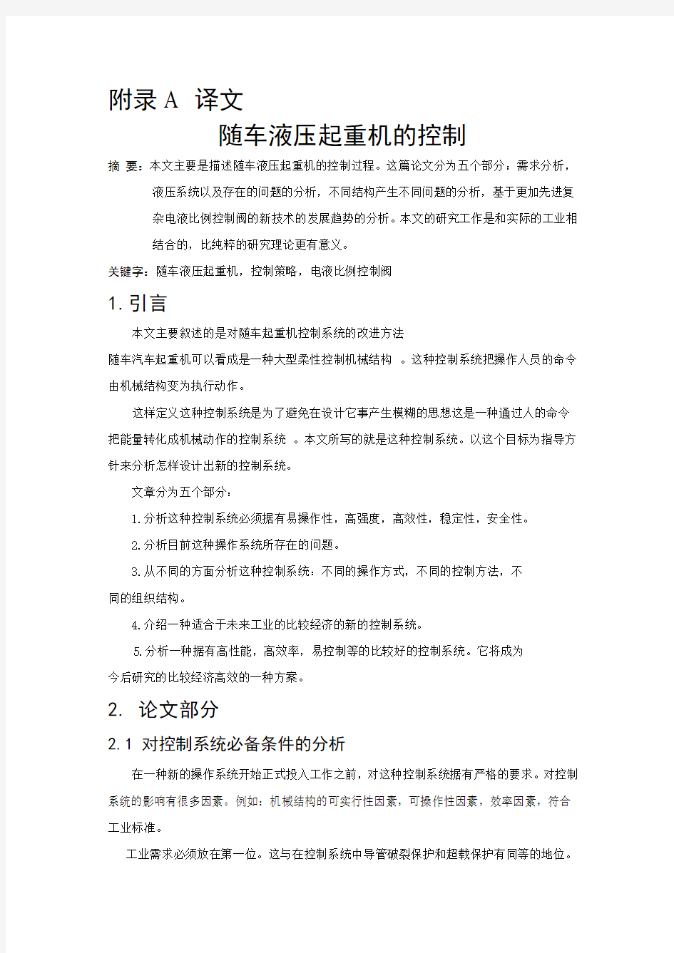
本文的中心是研究发展中的经济型机械控制方案的可实现问题,更多重点是先进的实验结果。实验结果由两种方法获得。第一种是通过研究单自由起重机实验台获得,第二种是通过研究一台由丹麦一家起重机厂送给英国的一所军校的起重机获得。如图1所示
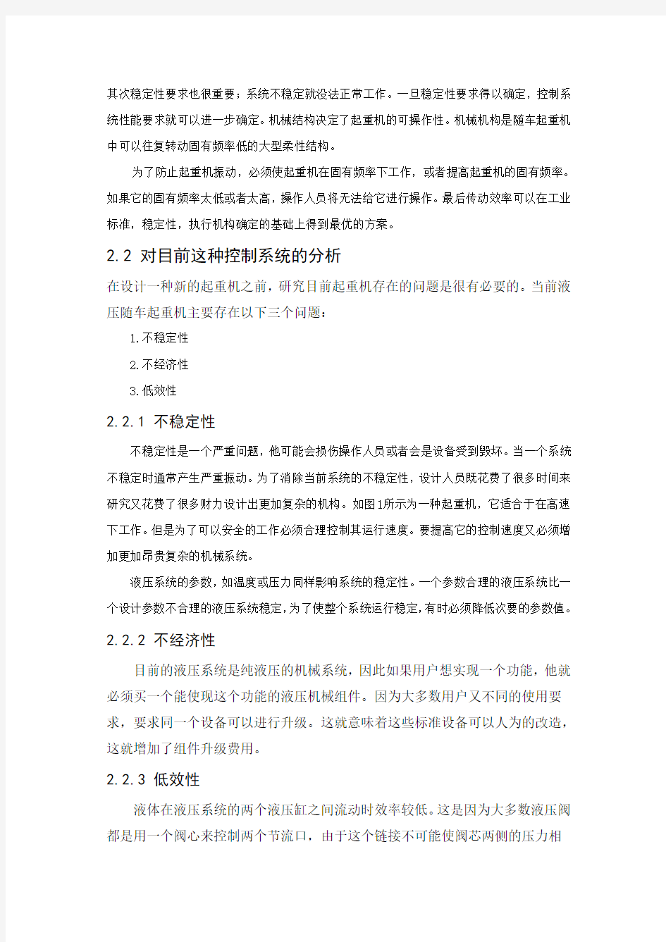
图1系统实验台左:单自由度起重机模型右:随车起重机实物虽然目前这种升缩分离机构在生产商中没有被普遍接受,但是两分离阀将会被逐渐取代。如图2所示是一种幅度-脉冲变换液压缸,它是通过数字信息处理器/奔腾双信息处理器运行程序来控制液压阀的。由数字信号处理器运行控制代码,奔腾处理器来判断并提供图形用户界面。
4. 当前工作
4.1 直线轴流控法
当今市场常见的直线流控器都需要压力补偿。压力补偿器可以使阀芯突然受压时保持恒定的压力。但是新增加的压力补偿器会使阀的结构比简单的随动阀更加复杂。另一种解决方法是用流控器测量阀的压力降来调整阀芯的位置来实现。这种想法虽然简单,但是由于压力传感器和微控器的费用比较高,想普遍运用于商品上是很难的。然而目前这种利用微控器和压力传感器的思想对于生产商来说是可以接受的。
虽然依据方程来看很简单,但是要实现却很难。流控器的位置精度取决于位置传感器的精度压力传感器的精度。噪声会影响位置传感器和压力传感器的稳定性。采用延时控制可以消除影响稳定性的噪声,这样,超过阀的运行范围的特征值用就不能用柏努力方程计算,应用更复杂的方程来计算。
图2升缩分离机构
4.2 液压缸控制方法
根据不同的受力方向和速度方向这种液压缸有四种工作情形。如图3所示:
多数是普通的随动液压阀,它这种控制方法已经在文献中可以找到,依靠一般的测量法测液压缸的速度位移相当复杂。它们也需要相当复杂的运算法则来控制。本文主要分析基于简单的PI控制器和没有严格速度位移要求的液压缸的控制方法。这种系统的控制方法比复杂的控制方法简单得多,由于它不需要特殊的传感器而且容易被大多数工程师理解所以比较容易被厂商采用。
在设计一种控制方法时另一种特别的控制方法也需要了解,它也是液控中常用的一种方法。移动液压阀要求低泄漏,以前的液压阀大们通常有很大的交迭。然而,使生产商能够接受的这种线轴式液压缸的驱动性能相当慢。这种具有很大交迭的重合以及激发很慢的液压阀很难满足现在的要求。交迭和较慢的驱动使压力控制变得相当困难。
新的控制方法可以用一个例子清楚简单的描述出来。从入口端实行流控制,出口端就实现液压力。流控制符合柏努力方程。液压控制过程中PI
控制器
图3起重机工作的不同情形
图4减压控制器
维持较小的压力来提高效率并且可以防止气穴现象。这些都是为了解决大交迭和较低的驱动所做的工作,压力控制器仅仅能排除控制中的一点问题。这就意味着如果控制人员想提高压力,却不能使液压缸移动,只能够降低控制口的开口量。这样做的作用只能使操作人员想改变活塞的方向时使它准时脱离零位。这种情况下外力方向和活塞运动仍然不能改变,这种方式需要改进。既然这样,需要压力控制器在出口变大时提供与外力方向相反的有用压力,当已知入口端的压力下降的时候,它可以增加与外力相反的压力。这个压力也受PI 控制器控制,如图4所示就是是一个这种控制系统的控制模型结构。
在写本文的时候这种控制的实验已经在图1所示的实验台上完成了,由于起重机上安装了载荷单向阀,所以稳定性没有达到要求。然而,用液压单向阀取代这种载荷单向阀,可以
使系统的稳定。在液压系统中,载荷闭式阀可以实现超载保护和卸载保护两种功能。由于在这种控制方法中使用伸缩阀机构对卸载保护很起作用,因此在起升机构中很有必要使用有这种功能的单向阀。一个操作单向阀的驾驶员可以做这一点,没有增加复杂的动力来阻止起重机的倾。安装了这种单向阀,起重机操作人员不需要再增加更复杂的外力来防止起重机产生倾翻。
5. 结束语
即使没有大量的实验设施,但是实验还是完成了,一个好的开始是成功的一半。这个论文题的大轮阔已经确定,它是有意义而且合理的。这个工作分为需求分析、目前的系统分析、不同布局分析、近期的解决办法的分析和最优解决方案的发展趋势分析五个部分。
在本
论题的最后,液压随车起重机的控制模将会被修改。
6.感谢语
感谢Danfoss Fluid Power A/S为这个研究提供了部分基金。也感谢H?jbjerg Maskinfabrik (HMF) A/S愿意为这种起重机的测试提供技术上的支持
随车液压起重机的轨迹控制
问题描述
这项方案是根据如图1所示的多自由度随车液压起重机控制问题提出来的。控制随车起重机要求操作人员技术相当高,它的操作机动范围很小。如果可以让现代的起重机实现遥控控制的话,操作人员只需要控制他手中的遥控器就可以控制起重机把重物放在他要求的任何地方。一个按钮控制一个自由度方向上的转动。因此只需要让操作人员得到熟练的训练他就可以每次控制更多的按钮来实现多个自由度的转动。
图1所示为一台随车液压装载起重机部分液压系统控制图实例
这项工程的目标是设计一台非熟练操作人员都能够控制的移动式液压起重机。操作人员根据吊具总成的合成轨迹控制一根操纵杆。这样不同的自由度就可以同时被控制。
多数随车液压起重机的结构就像图1所示的那
样,大多数都是非常柔性化的,因此当受载时它们
就会弯曲。这样做可以使起重机吊重比最低。事实
上吊重顶端位置也是制约控制系统结构偏差的因
素。这种问题可以通过一个好的位置偏差补偿控制
系统解决,这个系统还可以消除操作初期结构上发
生的摆动。 继续使结构轨迹偏差补偿控制系统在起重机
上进一步发展,起重机的装载能力将可以大大得到提高。当这种在起重机里的摆动可以被控制系统抑制的方法能够得到充分证明,在一个长的期限里可能有一个降低动力学安全系数的机会。这将使起重机生产商和用户节省一大笔费用。 吊具总成 图2
测试起重机图片
方案内容
现以一台如图2所示的HMF 680-4型随车液压起重机来分析这些问题。在这台起重机的不同位置安装了传感器来监视系统上的不同参数值,它们都是一些起重机上很重要的不同连接位置的压力、流量、应变参数值。实验测试可以证实起重机性能,所以可以通过精确的模型来测试起重机的性能。为了使所含盖的几个问题能够描述得更清楚,这些问题被简略的表述如下:
1.分析系统要求说明书
系统的执行标准分析已被完成。基于系统的这种要求连同确保系统的执行的检验程序将被列入清单。
2.机械子系统模型
许多技术模型已经存在,因此这些部件包括研究明确的模型局部动力学的表达方法。机械子系统的分析与局部模型偏差的详细分析相同。这样做是为了使计算的有效性能够明确表达出来,同时使系统的动作在控制过程中能够十分精确。基于这种非常有前景的用公式表示一个数学子系统模型的方法已经完成,它将从起重机试验台的实验结果中得到校验。
3.液压子系统模型
跟机械子系统建模一样,液压子系统模型由液压泵、不同的液压阀、激励源和液压导管组成。然而,并不是这些都要建模,只是那些对系统动力学部件影响比较大的成分才建模。液压子系统模型也需要用实验的方法来证明。除此之外是否在对偏差进行补偿时,系统中用了比重比较大的电液比例控制阀都必须被分析,即对机械结构的摆动进行分析。基于上述修正,对液压系统如果有必要都要做。
4.分析和标准的解决反转运动结构
起重机相对于底部有一个可以操作的特定空间,即吊具总成能达到的范围。这是公认的起重机工作范围。有的部位要通过不同的路线才可以达到。因此有必要在这些区域确定最佳的运动结构。有不同的参数标准,习惯上用起重机上总负荷的最小值,也就是在临界状态点的最小压力值。为了做这个重要的结构压力分析,基于实现这个运算法则的控制系统将进一步得到发展。
5.载荷判断方案的发展
为了实现起重机结构偏转补偿,需要知道起重机承受的有效载荷。因此,有必要进行不同的载荷在线可能情况分析,这样就可以判断哪一个传感器需要进行载荷复合鉴定。基于这种鉴定方案分析,可以实现最终的运算法则。
6. 控制运算法则的发展
基于这种机械液压子系统模型,一种吊具总成位置轨迹控制的控制规律将会得到发展。这种控制规律可以保证系统按照吊臂顶的运动轨迹运行,并且系统在工作情况下保持稳定。这包含在载荷判断和运动学最佳参数方案的分析中。
7. 控制系统的执行
最后系统的控制规律已经通过仿真试验得出,应该实现通过处理器或者数据信号处理检验系统实物了,即测试起重机。用这种测试方法将可以实现对系统制定测试,到测试结束的整个过程。这种测试技术还可以对一些典型系统进行控制。
机械化和自动化
自从18世纪末工业革命开始,工业机械化进程一直在不断地发展,并且变得越来越复杂。但目前的工业自动化过程较以前的工业自动化过程有很大的不同。20世纪的工业自动化之所以有别于18、19世纪的机械化,是因为机械化仅应用于操纵(执行)机构,而自动化则涉及整个生产单元中的执行和控制两个(核心)部分。尽管不是所有的情况,但在大多数情况下,控制元件依然发挥着强大的力量,机械化已经代替了手工劳动,而自动化代替了脑力劳动。
机械化程度的发展在过去和现在的区别不是很明显,而在一端是具有强大辨别和控制功能的饿电子计算机,另一端是我们目前所说的“转换机构”正如传输带一样与其他设备简单的连接起来。自动调整机构能够自动调节系统,也就是说,它能在没有人干预和调整的情况下,自动对系统或生产过程进行控制和调节。现代工业技术的核心因素就是当前人们经常提起的反馈(控制),它是以自动调节系统为基础,借助于系统偏差与期望之间的偏差来控制,可由自动检测、测量、显示和校正方法得到。反馈控制应用于高速运转的大型数字计算机进行复杂运算时,对于输入的复杂问题,计算机通常会一直运行,直到求出与问题匹配的结果。这或许于我们以前熟知的机器有很大的差别。同样的,反馈是我们所熟悉的机器概念。旧式的蒸汽机安装有离心传感器,控制杆上的两个小球不停的绕立轴旋转,气压升高,发动机转速变快,旋转控制器速度增加,使立杆上升,关闭阀门,切断蒸汽,从而发动机恢复到合适的速度。
随着工业革命的出现,机械化也随之产生,由于这时的机械化仅局限于单个生产过程。因此,需要使用人工控制每部机器及装卸材料,并把材料从一个地方运到另一个地方。仅仅在很少的情况下,这些生产过程才能够自动地衔接起来,形成连续的产品生产线。
一般而言,从20世纪20年代以来,尽管现代工业已经实现了高度机械化,然而通常机械化的部分还没有联系在一起。机械化的工厂生产了光电灯泡、瓶子和大量生产的产品的元件,这些机械化工厂的自动化程度日益得到了加强。20世纪40年代电子计算机的发展,意味着在机械控制领域内将出现大量比计算机更简单、更廉价的产品。这些装置—机械装置、气动装置、液压装置,在近些年内已有了很大的发展,并将继续发展下去,普通的观点认为这有利于自动控制的发展。当然不仅仅电子设备对目前自动控制的发展举足轻重,无疑在今后自动控制发展方面还继续会发挥不可估量的作用。
液压传动
对于两点之间较远的传动,不适合用传动带和传动链的机械系统,可优先考虑采用液压传动,液压传动的优点是:低速大力矩、机构紧密、稳定性高、无振动的平稳滑动,速度和方向能灵活控制,输出速度可实现无级快速变化。
由电力驱动的油泵提供有传递能量作用的油液,并可供给液压马达或油缸,从而将液压能转化成机械能。液压油流动是通过控制阀进行控制的,压力油的作用产生线性的或螺旋性的机械运动,此时的油液产生的动能相对低。因此,有时候使用静压传动。液压马达与液压泵的结构几乎是相同的,任何液压泵都可以当成马达应用,一定时间的流量可由调节阀使用变量泵来控制。
一般来说液压传动可分为直线式的和旋转式的,旋转式传动产生旋转运动,而活塞及缸体部件产生往返的运动是线性运动。
所有液压马达的功能基于同一个原理,压力油被交换地挤入、挤出到油腔中,进油循环由最小的腔体注油开始,当油腔达到最大容积时,油腔和油路隔开,停止进油,然后通过回油路油液返回到油箱中,同时另一个油腔开始进油。
计算机辅助设计技术
在广义上讲,计算机辅助设计(CAD)指的是计算机在解决设计问题中的应用。工程技术人员可以借助于直观显示屏幕、键盘、绘图仪和人机接口等诸多方式与计算机通信。工程技术人员可以提出问题并能很快有计算机得到解答。更确切地说,CAD是使工程技术人员和计算机系统工作,彼此发挥长处的技术。
过去,工程技术人员设计时所使用的传统工具是制图板、制图仪、计算器和技术数据图纸。后来,计算机的出现导致了工业中的巨大变化。随着数字控制、计算机数字控制、机床的引入,计算机在制造业中的应用在20世纪50年代末期首次有了实质性进展,通过磁带输入到机器中的数据控制了装配零件的机器运转。这一切对工程设计者并没有直接影响。
20世纪60年代初随着计算机辅助设计的引入产生了一场重大变革。CAD允许设计者以图形方式与计算机交互作用,工程技术人员能够检验一个设计思想,并很快地查看到设计效果,然后对其进行修改和重新评价。如此循环往复,直至形成一个合格的设计。每重复一次,设计方案都会得到一步的改善。因此,在时间、材料和资金允许的条件下所执行的循环次数越多,设计效果就越好。
计算机能加快设计进程,提高设计的精确程度。它能够在短时间内完成大量的、复杂的计算并得出准确可靠的结果。由于在有限的时间内某些设计所需要的大量计算不能简单的由人来完成,计算机的上述特征证明了作为一个设计工具的作用是无法估量的。
计算机可在磁盘或直接存储器等永久性介质上保存大量的信息。因此,以数字形式描述一个工程图纸的细目或一个汽车车身的造型,并把信息存储在存储器中都是可以做到的。这些数据能从存储器中检索、快速转换并显示在VDU(视频显示器)图形屏幕上,或交替地利用绘图仪绘制在图纸上。此外,设计者还可以迅速、容易地更新或修改图纸的任何部分。也能把修改后的图纸数据写回到存储器中。
计算机辅助设计在工程技术领域中有着重要的作用,例如,计算机系统生成工程图纸的应用;求解复杂构件的热应力问题的有限元技术的使用;机械装置和连接的分析及大量的辅助工程应用。
附录B 外文文献
CONTROL OF MOBILE HYDRAULIC CRANES
Marc E. MüNZER
Aalborg University
Institute of Energy Technology
Pontoppidanstr?de 101
DK-9220 Aalborg. Denmark
Email: mmun@iet. auc. dk
The goal of the thesis described in this paper is to improve the control of mobile hydraulic cranes. The thesis is split into five parts: a requirements analysis, an analysis of the current systems and their problems, an analysis of different possibiilities for system topologies, development of a new control system for the near future based on electro-hydraulic separate meter in / separate meter out valves, and finally an analysis of more advanced and complex solutions which can be applied in the more distant future. The work of the thesis will be done in cooperation with industry so the thesis will have more of an industrial focus than a purely theoretical focus. Key words: Mobile Hydraulic Cranes, Control strategies, Separate Meter-in/Separate Meter-out.
1INTRODUCTION
The goal of the thesis described in this paper is to improve the control of mobile hydraulic cranes. A mobile hydraulic crane can be thought of as a large flexible mechanical structure which is moved by some sort of control system, The control system takes its input from a human operator and translates this command into the motion of actuators which move the mechanical structure.
The definition of this control system is purposely left vague in order not to impose any constraints on its design. The control system consists of actuators which move the mechanical structure, a means of controlling the actuators, a means of supplying power to the actuators, and a way of accepting inputs from the operator. It is this control system which is the target of this thesis. The goal is to analyze the requirments made on the control system and present guidelines for the gesign of new control systems.
The thesis will be split into five parts:
1.Analysis of the requirements of the control system, from the perspective of the operator,
the mechanical system, efficiency, stability, and safety requirements.
2.Analysis of current control systems and what their problems are.
3.Analysis of the different options for the control system: different types of actuators
different types of control strategies, and different ways of organizing components.
4.Presentation of a new type of control system, which is commercially implementable. A
system that will meet the needs of industry in the near future.
5.Analysis of more optimized systems, with higher performance, better efficiency, more
flexible control, etc. This will be less commercially applicable but will be a starting
point for more research.
2SECTIONS OF THE THESIS
2.1Requirements Analysis of the Control System
Before starting detailed work on developing new control systems, it is important to analyze what the exact demands are on the control system. The control system is influenced by many factors.For example: the mechanical structure it is controlling, the human operator, efficiency, stability, and industry requlations.
Industry regulations are the first requirements that have to be addressed. Things like hose rupture protection and runaway load protection make a lot of demands on the control system. After regulations, stability is the next most important requirement; without stability the control system can’t be used. Once stability has been assured, the performance requirements of the control system have to be set. They are determined by the mechanical structure of the crane and the human operator. The mechanical structure of a mobile hydraulic crane is a very necessary to keep the speed of the control system below this natural frequency or to develop
a control system which can increase this frequency. The human operator also impossible limits on the control system. If the control system is too slow or too fast then it is impossible for a human operator to give it proper inputs. And finally, once the requlations have been met, stability is assured, and the performance is at the right level, the power efficiency of the control system has to be optimized.
2.2Analysis of Current Control Systems
Before designing a new control system it is good to analyze the current control systems to find out what their problems are. Current control systems are mainly hydraulic and can suffer from three main problems:
1.Instability
2.High cost
3.Inefficiency
2.2.1 Instability
Instability is a serious problem as it can cause injury to human operators or damage to equipment. When a system becomes unstable it usually starts to oscillate violently. To avoid instability in current systems, the designers either sacrifice certain functions which are desirable, or add complexity and cost. For example, in the crane shown in Figure 1, it would be desirable to have control over the speed. But due to the safety system that cranes are required to have, standard speed control is not stable. To add speed control requires a more complex and more expensive mechanical system.
The parameters of a hydraulic system, such as temperature or load force, also affect stability.
A system that is stable with one set of parameters might be unstable with another set. To ensure stability over the entire operating range of the system, performance must sometimes be sacrificed at one of the parameter range.
2.2.2High cost
Current systems are purely hydraulic-mechanical, so if the user wants a certain function, the user buys a certain hydraulic-mechanical component. Because most user have different requirements, there are many different variations of the same basic component. This means that many specialized components must be manufactured rather than one standard product. This drives up the cost of components.
2.2.3 Inefficiency
One form of inefficiency in current systems is due to the link between the flows of the two
ports of the cylinder. This is because most valves use a single spool to control the flow in both ports. Because of this link, it is impossible to set the pressure levels in the two sides of the cylinder independently. Therefore, the outlet side will develop a back pressure which acts in opposition to the direction of travel, which increases the pressure required on the inlet side to maintain motion. Since the force generated by the actuator is proportional to the pressure difference between the two sides, the actual pressures in the cylinder don’t affect the action of the cylinder. For example, the action of the cylinder for 0psi/600psi would be the same as 1000psi/1600psi. However, in the second case, the power supply would have to supply much more power. This extra power is wasted.
2.3Different Options for Control Systems
Current control systems use hydraulic actuators with directional/proportional valves to control the movement. However there are many different options for controlling a cylinder. Options range from new high performance electro-hydraulic valves, to separate meter in / separate meter out (SMISMO) valves, to hydraulic bus systems, to intelligent actuators with built in power supplies, to pump based control strategies. These systems all have advantages and disadvantages which need to be analyzed if the most optimum solution is to be chosen.
2.4Near Future Solution
It is expected that even if it is proven that a completely new system topology is the optimum configuration, the crane manufacturers and component manufacturers will not accept the new technology overnight. This will most likely take time, so an interim solution will be developed.
This solution will be made up of micro computer controlled Separate Meter In / Separate Meter Out (SMISMO) valves (Elfving, Palmberg 1997; Jansson, Palmberg, 1990; Mattila, Virvalo 1997). SMISMO valves will make it possible to implement new control strategies which are more efficient and stable. The micro computer will make it possible to introduce flexibility to valves. Variants can be programmed in software. This eliminates the need to manufacture hundreds of different variants. The crane manufacturer will be able to choose the exact functions he wants in his valve, while the component manufacturer will have to manufacture only one valve. This will lower the cost, even though the performance will have increased.
2.5Analysis of Higher Performance Solutions
This analysis will depend on the results of the analysis of different topologies. If it is shown that pump based control is to be the way of the future for example, then analysis will be performed in this area. Another area which will also be explored, is tool position control.
3LABORATORY FACILITIES
As the focus of this thesis is on developing control strategies that can be implemented on commercial machinery, much emphasis will be placed on experimental results. Experimental results will be obtained from two systems. The first, a simple one degree of freedom crane, was designed as an experimental platform. The second is a real crane which was donated to the University by Hojbjerg Maskinfabrik (HMF) a Danish crane manufacturer. Refer to Figure 1.
Figure 1 Experimental Systems in Laboratory. Left: One DOF crane model. Right: Real
Mobile Hydraulic Crane
As there are currently no commercially available separate meter-in/separate meter-out valves, two separate valves will be used instead. A sample circuit of one cylinder is shown in Figure 2. The control algorithms which control the valves, will be programmed on a Digital Signal Processor (DSP)/Pentium dual processor system. The DSP will run the control code and the Pentium will do diagnostics and provide a graphical user interface.
Figure 2 Separate Meter In / Separate Meter Out Setup
4CURRENT WORK
4.1Flow Control by Direct Actuation of the Spool
Most flow control valves on the market today work with a pressure compensator (Andersen; Ayers 1997). The pressure compensator keeps a constant pressure drop across the main spool of the valve, which keeps the flow constant. However, the addition of a pressure compensator makes the valve more complicated than a simple single spool valve. Another way of doing flow control is to measure the pressure drop across the valve and adjust the spool position to account for this
(Backé; Feigel 1990). This is not a new idea but has not been implemented commercially because of the high cost of pressure transducers and micro controllers. However, with the current drop in cost of micro controllers and pressure transducers this idea is now commercially feasible.
The concept is very simple, spool position is calculated from the Bernoulli equation using the pressure drop across the spool and reference flow.
Even though this is a simple equation, it is not easy to implement. The accuracy of the flow control is dependent on the precision of the position sensors and of the pressure transducers. Noise on the pressure or the position signals can cause stability problems. Filtering the noise, introduces delays in the control which can also affect stability. In addition the Bernoulli equation is not followed exactly over the entire operating range of the valve, so it may be necessary to store the valve characteristics as a data table or develop a more complex equation.
4.2Cylinder Control Strategy
To control a hydraulic cylinder, the strategy has to be able to handle four different situations depending on the directions of the load and the velocity of the cylinder. Refer to Figure 3.
Figure 3 Different Situations in Crane Operation
The control strategies that have appeared in the literature are usually quite complex and depend on measurements of the cylinder position and velocity (Elfving, Palmberg 1997; Mattila; Virvalo 1997). They are also based on rather complex control algorithms. It is the goal of this thesis to start with a control strategy which is based on simple PI controllers and makes no demands for position and velocity of the cylinder. The performance of this system will be lower than a complex control strategy, but it may be easier to implement commercially because it has no need for special sensors and is easier to understand for the average engineer.
Another feature which needs to be acknowledged when designing a control strategy, is the type of valve used. Mobile hydraulic valves demand low leakage and since most mobile valves are spool valves, they usually have large overlaps. In addition, to make the cost of the valve acceptable to industry, the actuation stage on the spool is usually quite slow. This combination of large overlap and slow actuation makes it hard to implement many of the strategies that have been presented. Pressure control especially becomes difficult when there is an overlap and a slow actuator.
One example of a new strategy which is simple and robust is described as follows. Flow control is implemented on the inlet side and pressure control is implemented on the outlet side. The flow control is based on the Bernoulli equation. Pressure control is done by PI controller which maintains a low constant pressure to increase the efficiency and prevent cavitation. To work around large overlaps and slow actuation stage, the pressure controller only does meter out control. This means that if the controller wishes to raise the pressure, it can’t add flow to the cylinder, it can only decrease the opening of the meter out port. The benefit of this is that the only time that the spool has to cross the zero position is when the operator wishes to change the direction of motion of the cylinder. For the case where the load force and the velocity are in the same direction, this strategy has to be modified. In this case, the pressure reference of the pressure controller at the outlet is increased to a value which opposes the load force. The pressure reference is increased when it is noticed that the pressure of the inlet side is dropping. The pressure reference is also controlled by a PI controller. A schematic model of the controller system for the load lowering case is shown in Figure 4.
At the time of writing this paper the initial experimental tests had performed on the real crane shown in Figure 1. Stability was not achieved because the crane is equipped with a load holding valve. However, the load holding valve will be replaced with a pilot operated check valve, which should make it possible to stabilize the system. In current systems, the load holding valve serves two functions, load holding and runaway load protection. Due to the use of a SMISMO valve setup, the runaway load protection is built into the control strategy, therefore the only function which is necessary for the load holding valve to perform is load holding. A pilot operated check valve will be able to do this, without adding complex dynamics which upset the stability of the system.
Figure 4 Controller Strategy for Lowering of Load
5CONCLUSION
Even though not much experimental work has been finished, a good start has been made and initial tests have been promising. The outline of the thesis has been developed and organized in a logical manner. The work is split into five parts, requirements analysis, analysis of current systems,
analysis of different topologies, development of a near future solution, and development of a more optimum solution. At the end of the thesis, the control of mobile hydraulic cranes will have been improved.
6ACKNOWLEDGEMENTS
This project is being funded in part by Danfoss Fluid Power A/S. The author would also like to thank Hojbjerg Maskinfabrik (HMF) A/S for the donation of the test crane.
机械设计 摘要:机器是由机械装置和其它组件组成的。它是一种用来转换或传递能量的装置,例如:发动机、涡轮机、车辆、起重机、印刷机、洗衣机、照相机和摄影机等。许多原则和设计方法不但适用于机器的设计,也适用于非机器的设计。术语中的“机械装置设计”的含义要比“机械设计”的含义更为广泛一些,机械装置设计包括机械设计。在分析运动及设计结构时,要把产品外型以及以后的保养也要考虑在机械设计中。在机械工程领域中,以及其它工程领域中,所有这些都需要机械设备,比如:开关、凸轮、阀门、船舶以及搅拌机等。 关键词:设计流程设计规则机械设计 设计流程 设计开始之前就要想到机器的实际性,现存的机器需要在耐用性、效率、重量、速度,或者成本上得到改善。新的机器必需具有以前机器所能执行的功能。 在设计的初始阶段,应该允许设计人员充分发挥创造性,不要受到任何约束。即使产生了许多不切实际的想法,也会在设计的早期,即在绘制图纸之前被改正掉。只有这样,才不致于阻断创新的思路。通常,还要提出几套设计方案,然后加以比较。很有可能在这个计划最后决定中,使用了某些不在计划之内的一些设想。 一般的当外型特点和组件部分的尺寸特点分析得透彻时,就可以全面的设计和分析。接着还要客观的分析机器性能的优越性,以及它的安全、重量、耐用性,并且竞争力的成本也要考虑在分析结果之内。每一个至关重要的部分要优化它的比例和尺寸,同时也要保持与其它组成部分相协调。 也要选择原材料和处理原材料的方法。通过力学原理来分析和实现这些重要的特性,如那些静态反应的能量和摩擦力的最佳利用,像动力惯性、加速动力和能量;包括弹性材料的强度、应力和刚度等材料的物理特性,以及流体润滑和驱动器的流体力学。设计的过程是重复和合作的过程,无论是正式或非正式的进行,对设计者来说每个阶段都很重要。 最后,以图样为设计的标准,并建立将来的模型。如果它的测试是符合事先要
液压传动 第十讲 制动器 力流体动力系统的优秀的特性之一是由电源产生,通过适当的控制和指导,并通过电线传输,就可以轻松转换到几乎任何类型的机械运动所需要用到的地方。使用一个合适的驱动装置,可以获得线性(直线)或者是旋转运动。驱动器是一种转换流体动力机械力和运动的装置。缸、马达和涡轮机是最常见的将流体动力系统应用于驱动设备的类型。这一章描述了各种类型的动作汽缸和他们的应用程序、不同类型的流体汽车和使用流体动力系统的涡轮机。 汽缸 制动汽缸是一种将流体动力转换成线性或直线、力和运动的装置。因为线性运动是沿着一条直线前后移动的往复运动。这种类型的制动器有时被称为一个往复、或线性、电动机。由ram或活塞组成的汽缸在一个圆柱孔内操作。制动汽缸可以安装,以便汽缸被固定在一个固定的结构,ram或活塞被连接到该机制来操作,或者是活塞和ram可能被固定到固定结构,汽缸附加到机械装置来操作。制动汽缸气动和液压系统的设计和操作是类似的。一些变化的ram和活塞式制动汽缸的内容将在后面的段落中描述。 冲压式缸 术语ram和活塞通常可以互换使用。然而,一个冲压式缸通常被认为是一个截面积活塞杆超过一半的截面积活动元件。在大多数这种类型的制动汽缸中,杆和活动元件各占一半。这种类型的活动元件经常被称为柱塞。冲压式缸主要是用来推动而不是拉。一些应用程序需要ram的一部分在平坦的外部来推动或升降单位操作。其他应用程序需要一些机械装置的附件,如一个U型夹或有眼螺栓。冲压式缸的设计在很多其他方面不同,以满足不同应用程序的要求。 单作用千斤顶 单作用千斤顶(如图:10-1)试用力只在一个方向。流体定向的汽缸取代ram 和他外部的弹性元件,将物体举起放在上面。
外文资料 In recent years, the hydraulic motor with brachytely and big torsional moment has great changes, the new structure continuously appears. But, all these hydraulic motors can be divided into two broad categories of single and multi-role according to the role of the number of plunger in each turn. The motors also can be divided into radial and horizontal direction according to the arrangement of the plunger. And the radial motors can be divided into different types according to structure and the summon power way of the plunger. No matter single and multi-role, the plug-hole of radial-piston hydraulic motor is equated by circle, arrayed radial. The plunger displaced by the impulse of pressure oil, then the volume of the cylinder changed, the summon power formed the rotation of the motor, all of these above are the mechanism of action of the motors. The rotor of the single role hydraulic motor has a circle of rotation, each plunger worker once reciprocation. The principal axis is eccentric axis in all the radial-piston hydraulic motors. The multi-role hydraulic motor had a guide rail curve, whose numbers are the action times. The rotor had a circle of rotation, the plunger worker many times reciprocal at the same time. The radial motors can be divided into several categories of plunger, ball blocker, blade. The structure of the single-role motors is simpler, the machine element number of it is less, the technology is better, and the cost is less. But the structure dimension of the single-role motor is longer than the multi-role motor in the same displacement each turn (or output torsional moment), and the single-role motor also have fluctuation of the output torsional moment and rotary speed.The homonymy high-pressure column tune of the single-role motor had major radial unbalance force that causes the brachytely stabilization of the motor became worse. Only increasing the capacity of the bearing, it can meet the requirements of the operating life of the bearing at the same time.
外文资料翻译译文 塔式起重机 动臂装在高耸塔身上部的旋转起重机。作业空间大,主要用于房屋建筑施工中物料的垂直和水平输送及建筑构件的安装。由金属结构、工作机构和电气系统三部分组成。金属结构包括塔身、动臂和底座等。工作机构有起升、变幅、回转和行走四部分。电气系统包括电动机、控制器、配电柜、连接线路、信号及照明装置等。 塔式起重机简称塔机,亦称塔吊,起源于西欧。据记载,第一项有关建筑用塔机专利颁发于1900 年。1905 年出现了塔身固定的装有臂架的起重机,1923 年制成了近代塔机的原型样机,同年出现第一台比较完整的近代塔机。1930 年当时德国已开始批量生产塔机,并用于建筑施工。1941 年,有关塔机的德国工业标准DIN8770 公布。该标准规定以吊载(t)和幅度(m)的乘积(tm)一起以重力矩表示塔机的起重能力。 我国的塔机行业于20 世纪50 年代开始起步,相对于中西欧国家由于建筑业疲软造成的塔机业的不景气, 上海波赫驱动系统有限公司我国的塔机业正处于一个迅速的发展时期。 从塔机的技术发展方面来看,虽然新的产品层出不穷,新产品在生产效能、操作简便、保养容易和运行可靠方面均有提高,但是塔机的技术并无根本性的改变。塔机的研究正向着组合式发展。所谓的组合式,就是以塔身结构为核心,按结构和功能特点,将塔身分解成若干部分,并依据系列化和通用化要求,遵循模数制原理再将各部分划分成若干模块。根据参数要求,选用适当模块分别组成具有不同技术性能特征的塔机,以满足施工的具体需求。推行组合式的塔机有助于加快塔机产吕开发进度,节省产品开发费用,并能更好的为客户服务。 塔机分为上回转塔机和下回转塔机两大类。其中前者的承载力要高于后者,在许多的施工现场我们所见到的就是上回转式上顶升加节接高的塔机。按能否移动又分为:走行式和固定式。固定式塔机塔身固定不转,安装在整块混凝土基础上,或装设在条形式X 形混凝土基础上。在房屋的施工中一般采用的是固定式的。 设备特点和安全装置 塔式起重机的动臂形式分水平式和压杆式两种。动臂为水平式时,载重小车沿水平动臂运行变幅,变幅运动平衡,其动臂较长,但动臂自重较大。动臂为压杆式时,变幅机构曳引动臂仰俯变幅,变幅运动不如水平式平稳,但其自重较小。 为了确保安全,塔式起重机具有良好的安全装置,如起重量、幅度、高度和载荷力矩等限制装置,以及行程限位开关、塔顶信号灯、测风仪、防风夹轨器、爬梯护身圈、走道护栏等。司机室要求舒适、操作方便、视野好和有完善的通讯设备。 塔式起重机的检验产要点 1) 检查金属结构情况特别是高强度的螺栓,它的连接表面应清除灰尘、油漆、没迹和锈蚀,并且使用力矩手或专用扳手,按装配技术要求拧紧。 2) 检查各机构传动系统,包括各工作传动机构的轴承间隙是否合适,齿轮啮合是不是良好及制动器是否灵敏。 3) 检查钢丝绳及滑轮的磨损情况,固定是否可靠。 4) 检查电气元件是否良好,名接触点的闭合程度,接续是否正确和可靠。 5) 检查行走轮与轨道接触是否良好,夹轨钳是否可靠。装设附着装置、内爬装置时,各连接螺栓及夹块是否牢固可靠。
外文资料译文 液压系统 绪论 液压站又称液压泵站,是独立的液压装置。 它按逐级要求供油。并控制液压油流的方向、压力和流量,适用于主机与液压装置可分离的各种液压机械上。 用户购后只要将液压站与主机上的执行机构(油缸或油马达)用油管相连,液压机械即可实现各种规定的动作和工作循环。 液压站是由泵装置、集成块或阀组合、油箱、电气盒组合而成。各部件功能为: 泵装置--上装有电机和油泵,是液压站的动力源,将机械能转化为液压油的压力能。 集成块--由液压阀及通道体组装而成。对液压油实行方向、压力和流量调节。 阀组合--板式阀装在立板上,板后管连接,与集成块功能相同。 油箱--板焊的半封闭容器,上还装有滤油网、空气滤清器等,用来储油、油的冷却及过滤。 电气盒--分两种型式。一种设置外接引线的端子板;一种配置了全套控制电器。 液压站的工作原理:电机带动油泵转动,泵从油箱中吸油供油,将机械能转化为液压站的压力能,液压油通过集成块(或阀组合)实现了方向、压力、流量调节后经外接管路并至液压机械的油缸或油马达中,从而控制液动机方向的变换、力量的大小及速度的快慢,推动各种液压机械做功。 1.1发展历程 我国液压(含液力,下同)、气动和密封件工业发展历程,大致可分为三个阶
段,即:20世纪50年代初到60年代初为起步阶段;60~70年代为专业化生产体系成长阶段;80~90年代为快速发展阶段。其中,液压工业于50年代初从机床行业生产仿苏的磨床、拉床、仿形车床等液压传动起步,液压元件由机床厂的液压车间生产,自产自用。进入60年代后,液压技术的应用从机床逐渐推广到农业机械和工程机械等领域,原来附属于主机厂的液压车间有的独立出来,成为液压件专业生产厂。到了60年代末、70年代初,随着生产机械化的发展,特别是在为第二汽车制造厂等提供高效、自动化设备的带动下,液压元件制造业出现了迅速发展的局面,一批中小企业也成为液压件专业制造厂。1968年中国液压元件年产量已接近20万件;1973年在机床、农机、工程机械等行业,生产液压件的专业厂已发展到100余家,年产量超过100万件,一个独立的液压件制造业已初步形成。这时,液压件产品已从仿苏产品发展为引进技术与自行设计相结合的产品,压力向中、高压发展,并开发了电液伺服阀及系统,液压应用领域进一步扩大。气动工业的起步比液压稍晚几年,到1967年开始建立气动元件专业厂,气动元件才作为商品生产和销售。含橡塑密封、机械密封和柔性石墨密封的密封件工业,50年代初从生产普通O型圈、油封等挤压橡塑密封和石棉密封制品起步,到60年代初,开始研制生产机械密封和柔性石墨密封等制品。70年代,在原燃化部、一机部、农机部所属系统内,一批专业生产厂相继成立,并正式形成行业,为密封件工业的发展成长奠定了基础。 进入80年代,在国家改革开放的方针指引下,随着机械工业的发展,基础件滞后于主机的矛盾日益突出,并引起各有关部门的重视。为此,原一机部于1982年组建了通用基础件工业局,将原有分散在机床、农业机械、工程机械等行业归口的液压、气动和密封件专业厂,统一划归通用基础件局管理,从而使该行业在规划、投资、引进技术和科研开发等方面得到基础件局的指导和支持。从此进入了快速发展期,先后引进了60余项国外先进技术,其中液压40余项、气动7项,经消化吸收和技术改造,现均已批量生产,并成为行业的主导产品。近年来,行业加大了技术改造力度,1991~1998年国家、地方和企业自筹资金总投入共约20多亿元,其中液压16亿多元。经过技术改造和技术攻关,一批主要企业技术水平进一步提高,工艺装备得到很大改善,为形成高起点、专业化、批量生产打下了良好基础。近几年,在国家多种所有制共同发展的方针指引下,不同所有制的中小企业迅猛崛起,呈现出
A controller enabling precise positioning and sway reduction in bridge and gantry cranes Khalid L. Sorensen, William Singhose, Stephen Dickerson The George W. Woodruff School of Mechanical Engineering, Georgia Institute of Technology, 813 Ferst Dr., MARC 257, Atlanta, GA 30332-0405, USA Received 28 September 2005; accepted 30 March 2006 Available online 5 June 2006 一个控制器使门式起重机和减摇桥精确定位 Khalid L. Sorensen, William Singhose, Stephen Dickerson, 乔治亚机械工程学院,乔治亚技术学院, Ferst博士813,MARC 257 ,亚特兰大,GA 30332-0405,美国,2005年9月28日收到,2006年3月30日接受,2006年6月5日可在线使用.
一个控制器使门式起重机和减摇桥精确定位 摘要 起重机是很难精确操纵载荷的。振荡,可以诱导成大桥或手推车的阻尼系统轻度运动,并且还对环境造成滋扰. 为解决上述两种振荡的来源,结合反馈和输入整形控制器的发展。该控制器是由三个不同的模块组成,反馈模块的检测和定位误差补偿; 第二反馈模块侦测并拒绝振动; 使用塑料造填充的第三个模块,以减轻振荡。一个使用精确的模型矢量驱动的交流感应马达,为典型的大型起重机, 用同一个褶分析技术,将非线性动力学起重机器分为对照设计。在佐治亚技术学院实验10吨桥式起重机控制器。该控制器具有良好的定位精度和性能以减少摆动.。 关键词:输入整形;指挥整形;起重机控制;振动控制;防摇;桥式起重机;龙门吊床 1. 绪论 桥、门式起重机在工业生产中占据了关键地位。它们被使用在世界各地数以千计的船场、建筑工地、钢铁厂、仓库、核电厂及废料储存设施,以及其他工业园区。这种操纵系统的及时性和有效性为工业生产力起了重要贡献。因此,可以提高企业经济效益的起重机是极其宝贵的。这些结构,见图一。1.被给予高度评价的压电性质.、抗外部干扰,如风力或气压 (例如桥梁或小车) 能造成载荷振动。在许多实际生产中,这些振动产生了不良后果。摇动使得有效载荷或钩的精确定位在一人操作的时候费时费力;此外,当载荷或周边障碍有是一个危险和脆弱的时候,振荡可能存在安全风险。广泛使用的桥、门式起重机,再加上要控制不必要的振荡,使得大量的研究与控制这些结构有了干劲。工程师们正试图改善其易用性,以增加经济效益,并减轻安全上的顾虑,起重机系统的三个主要要解决的方面: (1)运动诱发的振荡;(2)扰动诱发的振荡;(3)定位能力。一个15吨的桥式起重机采用鲁棒输入整形技术来减少运动诱发的振荡(Singer,Singhose, & Kriikku,1997)。莱利建议控制小车位置和振荡通过比例-微分( PD )控制,在这之间的耦合电缆角和运动的小车将被增加(Fang,Dixon, Dawson, & Zergeroglu, 2001)。Piazzi提出了动态基于逆控制以降低瞬态和残余运动诱发振荡(Piazzi & Visioli, 2002)。金大中推行了极点配置策略,对一个真正的集装箱起重机运动控制和振荡以及定位(Kim, Hong, & Sul, 2004) 。 Moustafa今日发达非线性控制载荷轨迹律跟踪基于Lyapunov的稳定性分析((Moustafa, 2001) 。奥康纳制定了控
液压机外文翻译文献 (文档含中英文对照即英文原文和中文翻译) 原文: The Analysis of Cavitation Problems in the Axial Piston Pump shu Wang Eaton Corporation, 14615 Lone Oak Road, Eden Prairie, MN 55344 This paper discusses and analyzes the control volume of a piston bore constrained by the valve plate in axial piston pumps. The vacuum within the piston bore caused by the rise volume needs to be compensated by the flow; otherwise, the low pressure may cause the cavitations and aerations. In the research, the valve plate geometry can be optimized by some analytical limitations to prevent the piston pressure below the vapor pressure. The limitations provide the design guide of the timings and
overlap areas between valve plate ports and barrel kidneys to consider the cavitations and aerations. _DOI: 10.1115/1.4002058_ Keywords: cavitation , optimization, valve plate, pressure undershoots 1 Introduction In hydrostatic machines, cavitations mean that cavities or bubbles form in the hydraulic liquid at the low pressure and collapse at the high pressure region, which causes noise, vibration, and less efficiency. Cavitations are undesirable in the pump since the shock waves formed by collapsed may be strong enough to damage components. The hydraulic fluid will vaporize when its pressure becomes too low or when the temperature is too high. In practice, a number of approaches are mostly used to deal with the problems: (1) raise the liquid level in the tank, (2) pressurize the tank, (3) booster the inlet pressure of the pump, (4) lower the pumping fluid temperature, and (5) design deliberately the pump itself. Many research efforts have been made on cavitation phenomena in hydraulic machine designs. The cavitation is classified into two types in piston pumps: trapping phenomenon related one (which can be prevented by the proper design of the valve plate)and the one observed on the layers after the contraction or enlargement of flow passages (caused by rotating group designs) in Ref. (1). The relationship between the cavitation and the measured cylinder pressure is addressed in this study. Edge and Darling (2) reported an experimental study of the cylinder pressure within an axial piston pump. The inclusion of fluid momentum effects and cavitations within the cylinder bore are predicted at both high speed and high load conditions. Another study in Ref. (3) provides an overview of hydraulic fluid impacting on the inlet condition and cavitation potential. It indicates that
附录A Portal power China’s rapid economic growth in the past decade has resulted in a big increase in freight traffic through the country’s seaports . Old ports are being expanded and new ports built to handle the large growth in container and bulk cargo traffic all along the Chinese coastline. China’s port expansion programme has provided a strong boost to the domestic port equipment industry, which has enjoyed a strong increase in demand for port cranes of various types, including container cranes and portal cranes along with bulk cargo handling equipment. State-run China Harbour Engineering (group) Corporation Ltd, established under the ruling State Council, is China’s largest supplier of port cranes and bulk cargo handling equipment. The organization controls both Shanghai Zhenhua Port Machinery Co Ltd (ZPMC),the world’s largest manufacturer of quayside container cranes, and Shanghai Port Machinery Plant (SPMP), which specializes in the manufacturer of portal cranes and other cranes used in ports along with dry bulk cargo handling equipment. SPMP’s main market is China, although the company is looking to expand its overseas sales. Although less well known than its associate ZPMC, SPMP also operates large manufacturing facilities, and is due to move part of its production shortly to Changxing Island near Shanghai where ZPMC already operates a large container crane fabrication plant. Portal and other harbour cranes are SPMP’s major production item. During the past two years, the corporation has won contracts for 145 portal cranes from port authorities throughout China, both from new ports under construction and ports undergoing expansion. In recent years, SPMP has also supplied portal cranes to the United States, Iraq,and Myanmar.The port Rangoon of Myanmar in has purchased a 47m,40t portal crane while BIW of the United States has purchased three cranes-15t,150t, and 300t portal
中英文资料对照外文翻译文献综述 液压系统 液压传动和气压传动称为流体传动,是根据17世纪帕斯卡提出的液体静压力传动原理而发展起来的一门新兴技术,1795年英国约瑟夫?布拉曼(Joseph Braman,1749-1814),在伦敦用水作为工作介质,以水压机的形式将其应用于工业上,诞生了世界上第一台水压机。1905年将工作介质水改为油,又进一步得到改善。 第一次世界大战(1914-1918)后液压传动广泛应用,特别是1920年以后,发展更为迅速。液压元件大约在 19 世纪末 20 世纪初的20年间,才开始进入正规的工业生产阶段。1925 年维克斯(F.Vikers)发明了压力平衡式叶片泵,为近代液压元件工业或液压传动的逐步建立奠定了基础。20 世纪初康斯坦丁?尼斯克(G?Constantimsco)对能量波动传递所进行的理论及实际研究;1910年对液力传动(液力联轴节、液力变矩器等)方面的贡献,使这两方面领域得到了发展。 第二次世界大战(1941-1945)期间,在美国机床中有30%应用了液压传动。应该指出,日本液压传动的发展较欧美等国家晚了近 20 多年。在 1955 年前后 , 日本迅速发展液压传动,1956 年成立了“液压工业会”。近20~30 年间,日本液压传动发展之快,居世界领先地位。 液压传动有许多突出的优点,因此它的应用非常广泛,如一般工业用的塑料加工机械、压力机械、机床等;行走机械中的工程机械、建筑机械、农业机械、汽车等;钢铁工业用的冶金机械、提升装置、轧辊调整装置等;土木水利工程用的防洪闸门及堤坝装置、河床升降装置、桥梁操纵机构等;发电厂涡轮机调速装置、核发电厂等等;船舶用的甲板起重机械(绞车)、船头门、舱壁阀、船尾推进器等;特殊技术用的巨型天线控制装置、测量浮标、升降旋转舞台等;军事工业用的火炮操纵装置、船舶减摇装置、飞行器仿真、飞机起落架的收放装置和方向舵控制装置等。 一个完整的液压系统由五个部分组成,即动力元件、执行元件、控制元件、辅助元
毕业设计(论文)外文资料翻译 系(院):电子与电气工程学院 专业:电气工程及其自动化 姓名: 学号: 外文出处: (用外文写)Baidu library 附件: 1.外文资料翻译译文;2.外文原文。 注:请将该封面与附件装订成册。
附件1:外文资料翻译译文 基础防雷 简介 闪电是一个反复无常,随机和不可预测的事件。它的物理特征包括:电流超过400 kA;温度超过50000华氏度,速度接近或超过三分之一的光速。自2000年以来持续雷击地球约100次每秒。美国保险公司的资料显示每57索赔有一次是因为雷击损坏。这些数据还不包括商业,政府和工业雷电造成的损失。在美国每年因雷电造成的火灾超过26000起,财产损失在5-6亿美元。 地球上的雷击现象,按目前的技术角度来看,遵循一个近似的规律: 1。从顶层雷云朝地球的向下脉冲,寻求电气地面目标。 2。地基对象(围栏,树木,草叶,建筑,避雷针,等等)对此事件发出不同程度的电力活动。从这些地基对象向上发送电力波动,在离地面几十米的位置,会出现一个“聚集区”加剧当地的电场。 3。当带有异种电荷的雷云相遇,相当于电路“开关”被关闭,于是有电流流过。我们就会看到闪电。 闪电效果可以直接也可能是间接的。直接影响是有电阻发热,出现电弧并可能燃烧起来。间接影响是,多数时候对电容,电感出现电磁影响。在绝对意义上实现闪电的防护是不可能的,只能使其产生的影响减少,可以由一个整体性,系统性的风险缓解办法来实现保护。下面对通用条款进行描述。 避雷针 从富兰克林研究雷电开始,就使用避雷针进行建筑物防雷并引流接地。避雷针,是现在最常用的防雷装置,根据建筑物不同的地点,高度和形状,使用合适类型的避雷针来达到设计要求。一些公共事业如架空线、变电所喜欢屏蔽电线。在某些情况下,没有任何避雷装置的使用是最适当的。 高空避雷装置的使用可能会改变闪电的动作。在等效电力场所,钝尖杆被看作是一种有效的避雷针类型。高空防雷装置的设计和性能是一个有争议的并尚未解决
毕业设计论文外文资料翻译 附件1:外文资料翻译译文 起重机的工作需要更多的科学技术 起重机的出现大大提高了人们的劳动效率,以前需要许多人花长时间才能搬动的大型物件现在用起重机就能轻易达到效果,尤其是在小范围的搬动过程中起重机的作用是相当明显的。 战后的前几年,世界性的工业诞生了,起重机行业几乎完全停止。然而到这个年代末,起重机的建造变得多元化并传播到世界各地,它的前所未有的蓬勃发展似乎整个工业注入了新能源。轻型起重机投入到工作地点并准备作为主要机械,因为人们意识到了在工作间不用拆除他们的的优点。这些新的设计也不再需要其他起重设备协助操纵——相比以前在安装前要进行繁琐的设计。但是,在这一切之前发生了恐怖的第二次世界大战。到1940年,欧洲完全陷入了战争中。到战争结束后的几十年来,欧洲和世界其他地区发生了巨大的政治,经济和社会变化,将影响整个社会结构,包括建造业和起重机行业。在美国,蒸汽机已开始改为柴油机——到1953年超过百分之五十的机车将使用柴油机。战争期间,挖掘机,铲运机和起重机的大规模生产在继续。例如1940年,看到Thew推出新的'Lorain Motocrane'系列。这其中包括三种起重机,是历史上首次自身安装了底盘的起重机。最小的MC - 2 ,起重量达7.6吨,MC – 2起重量为9.9吨,MC – 3起重量为13.5吨。这些起重机许多被用于军队,有的还安装在港口用作港湾式起重机(在MC - 4型)。当然,这场战争已经削弱了能在起重机行业工作的健壮的男人的数量,并且优秀的起重机司
机严重短缺。在Thew ,一位毕业于美国海军学院的经验丰富的技工A C Burch和L K Jenkins进行了为期两天的起重机业务课程的教授。这两位绅士好比是我们今天所知的―经营者培训‖的创始人。他们实际上已设计了动力起重机,都深深地了解起重机,并很高兴传授这方面的知识。 当日本国家铁路公司致力于采购一种旨在搬动钢轨扣板的原型机,潮流逆转。该设备工作极为出色。iVlasuo Tadano环游日本,用35毫米的电影展示该设备的强大用途。沿路上,他获取了大量订单。同时,他好像成为当今市场营销专家所宠爱的公司影像传播的先驱! 其他国家也在大力发展起重机。特别是意大利,逐渐发展成为该行业的创新基地。1948年Carlo Raimodi在米兰附近的Legnano,首次建造了回转塔式起重机,一种经典的顶端回转起重机。公司最初成立于1863年,在生产起重机之前,是一间铸造厂并为技工和其他行业生产机械设备。当时全球建筑业空前繁荣,吸引了专业设备制造商的注意。其中许多公司在推广起重机后,推出了混凝土搅拌设备。提供了多种不同组合,例如,Reich, Ibag和Liebherr设计开发了起重机与混凝土搅拌设备一起使用的组合。 桥式起重机小车运行机构设计主要包括起升机构、小车架、小车运行机构、吊具等部分。其中的小车运行机构主要由减速器、主动轮组、从动轮组、传动轴和一些连接件组成。桥式起重机是水电站桥式起重机,安装于丰满水电站扩建工程厂房内,用于水轮发电机组及其附属设备的安装和检修工作。水电站内设备一般都是大中型设备,对桥式起重机的载荷要求较高,所以对减速器性能要求较高。 桥式抓斗起重机是桥架在高架轨道上运行,由起重小车带动抓斗抓取物料的一种桥架型起重机。桥架沿铺设在两侧高架上的轨道纵向运行,起重小车沿铺设在桥架上的轨道横向运行,构成矩形的工作范围,就可以充分利用桥架下面的空间吊运物料,不受地面设备的阻碍。桥式抓斗起重机广泛应用于电厂、煤厂等需要散料装卸的场合,由于该设备笨重,运输安装困难,对其产品质量检测一般需要在现场进行。所以要求控制设备接线方便,体积小便于携带。又由于使用现场条件不动,还要求检测设备有随机手动控制功能,以保证运行时的安全。随着对起重运输机械控制要求的不断提高,控制手段也越来越先进。目前国内的桥式起重机控制系统都需要人在现场进行控制,控制方式都比较落后。在中小型起重机中, 大都采用控制器直接控制大、小车运行, 主、副钩提升、下降重物及调速。
附录: 外文资料与中文翻译 外文资料: Hydraulic System Hydraulic presser drive and air pressure drive hydraulic fluid as the transmission is made according to the 17th century, Pascal's principle of hydrostatic pressure to drive the development of an emerging technology, the United Kingdom in 1795 ? Braman Joseph (Joseph Braman ,1749-1814), in London water as a medium to form hydraulic press used in industry, the birth of the world's first hydraulic press. Media work in 1905 will be replaced by oil-water and further improved. After the World War I (1914-1918) ,because of the extensive application of hydraulic transmission, espec- ially after 1920, more rapid development. Hydraulic components in the late 19th century about the early 20th century, 20 years, only started to enter the formal phase of industrial production. 1925 Vickers (F. Vikers) the invention of the pressure balanced vane pump, hydraulic components for the modern industrial or hydraulic transmission of the gradual establishment of the foundation. The early 20th century G ? Constantimscofluct- uations of the energy carried out by passing theoretical and practical research; in 1910 on the hydraulic trans- mission (hydraulic coupling, hydraulic torque converter, etc.) contributions, so that these two areas of develo- pment. The Second World War (1941-1945) period, in the United States 30% of machine tool applications in the hydraulic transmission. It should be noted that the development of hydraulic transmission in Japan than Europe
中国地质大学长城学院 本科毕业设计外文资料翻译 系别工程技术系 专业机械设计制造及其自动化 学生姓名彭江鹤 学号 05211534 指导教师王泽河 职称教授 2015 年 5 月 4 日
液压传动系统 作者:Hopmans, ArthurH. 摘要 液压传动是由液压泵、液压控制阀、液压执行元件和液压辅件组成的液压系统。液压泵把机械能转换成液体的压力能,液压控制阀和液压辅件控制液压介质的压力、流量和流动方向,将液压泵输出的压力能传给执行元件,执行元件将液体压力能转换为机械能,以完成要求的动作。 关键词:液压传动;气压传动;传动系统; 许多液压传动先前已经设计出允许操作者无限变化输出的变速器,或甚至逆转的传动装置的输出作为相对于输入。通常情况下,这已经通过使用一个旋转斜盘是要么由操作者手动或操作液压动机来改变通过旋转泵头部具有轴向移动的活塞流动的液压流体的。液压流体从泵头活塞的流动,依次转动的马达头通过激励相应的一组活塞在其中违背一固定凸轮的,因此,旋转安装在电动机头的输出轴。 通常情况下,在现有技术的变速器已被被设置有各种功能,例如齿轮减速,刹车设定装置等。不幸的是,这些功能通常是提供外部发送的和显著增加整个装置的体积和质量。申请人确定,这是很期望具有其中基本上所有的这些需要或希望的功能,可以在内部提供的发送,同时还产生一个非常有效的和非常有效的传输的综合传输。 特别是,这种类型的变速器上经常使用的设备,如“零转动半径”剪草机之类的其中一个潜在的危险情况面对操作者,旁观者和设备本身,如果设备我们允许继续被推进应的操作者释放控制,由于当操作者无意中从装置抛出或变得受伤。因此,“故障自动刹车”机制经常被设置为传输自动地返回到中立配置在这种情况下,使得该装置不会继续供电,如果控制被释放。 先前传输这种类型的一般依靠某种外部设备,比如其目的是为了在操作者控制轴返回到中立位置应操作者释放所述轴的反操作偏压弹簧。这种类型的外部设备,可以容易地由用户或篡改损坏。这种回归函数中性到传输本身的整合允许在外部零件的减少可被损坏或不适当取出并大大降低,以支持传输的各种功能所需的外部结构。 在这种类型的用于割草机的使用和类似的传输经常遇到的另一个问题是,操作时会略生涩或有弹性,因为操作者通常无法顺利地控制从一个速度到另一个的过渡,往往试图使突然变化。从这些生涩的操作震动有一种倾向,穿更重的机器和操作上也是如此。因此,理想的是抑制这种传输的输出,以防止这种不平稳的运动。 不仅是它是期望能够有一个返回到中立的功能,如desribed以上,但还希望为操作者有积极的感觉为中立位置时,不论操作者从空档移动到前进或从中立扭转。此功能在本文中称为积极中性功能,并且在一般情况下,该功能需要操作者在从发送到任何一个正向或反向方向的中立姿势变换扩展更多的能量或运动相比,量能量消耗或运动需从一个速度转移到另一个在一个特定的方向。与上面提到的其它特征,最好是需要提供此功能的结构的发送本身内掺入。