Windows Server 2016 Hyper-Converged Solution - Virtual Machines and Software Defined Storage on the Same Cluster
Windows Server 2016 Technical Preview introduces Storage Spaces Direct, which enables building highly available (HA) storage systems with local storage. This is a significant step forward in Microsoft Windows Server software-defined storage (SDS) as it simplifies the deployment and management of SDS systems and also unlocks use of new classes of disk devices, such as SATA and NVMe disk devices, that were previously not possible with clustered Storage Spaces with shared disks.
Windows Server 2016 provides a hyper-converged solution by allowing the same set of servers to provide SDS, through Storage Spaces Direct (S2D), and serve as the hosts for virtual machines using Hyper-V. The same
How to Use this Guide:
This document provides both an introductory overview and specific standalone examples of how to deploy a Hyper Converged Solution with Storage Spaces Direct.
Before taking any action, it is recommended that you do a quick read through of this document to familiarize yourself with the overall approach, to get a sense for the important Notes associated with some steps, and to acquaint yourself with the additional supporting resources and documentation. Hyper-converged Solution with Software Defined Storage Overview
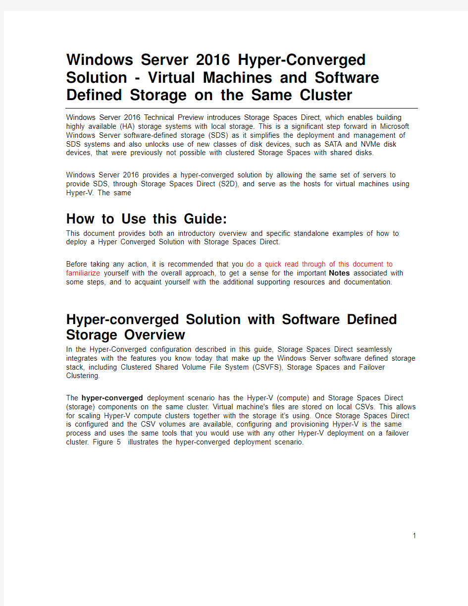
In the Hyper-Converged configuration described in this guide, Storage Spaces Direct seamlessly integrates with the features you know today that make up the Windows Server software defined storage stack, including Clustered Shared Volume File System (CSVFS), Storage Spaces and Failover Clustering.
The hyper-converged deployment scenario has the Hyper-V (compute) and Storage Spaces Direct (storage) components on the same cluster. Virtual machine's files are stored on local CSVs. This allows for scaling Hyper-V compute clusters together with the storage it’s using. Once Storage Spaces Direct is configured and the CSV volumes are available, configuring and provisioning Hyper-V is the same process and uses the same tools that you would use with any other Hyper-V deployment on a failover cluster. Figure 5 illustrates the hyper-converged deployment scenario.
1
FIGURE 5: Hyperconverged – same cluster configured for Storage Spaces Direct and the hosting of virtual machines
Hardware requirements
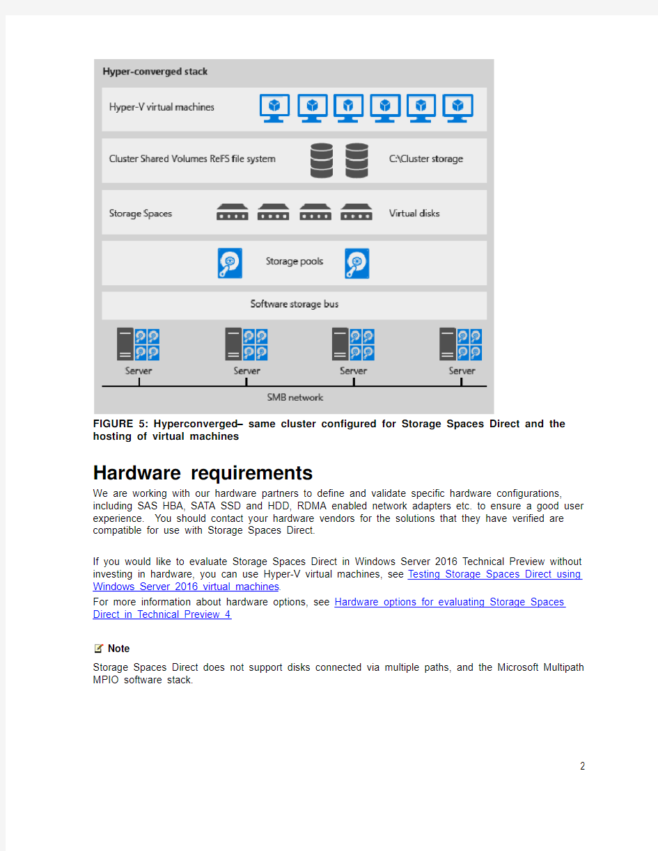
We are working with our hardware partners to define and validate specific hardware configurations, including SAS HBA, SATA SSD and HDD, RDMA enabled network adapters etc. to ensure a good user experience. You should contact your hardware vendors for the solutions that they have verified are compatible for use with Storage Spaces Direct.
If you would like to evaluate Storage Spaces Direct in Windows Server 2016 Technical Preview without investing in hardware, you can use Hyper-V virtual machines, see Testing Storage Spaces Direct using Windows Server 2016 virtual machines.
For more information about hardware options, see Hardware options for evaluating Storage Spaces Direct in Technical Preview 4
Note
Storage Spaces Direct does not support disks connected via multiple paths, and the Microsoft Multipath MPIO software stack.
2
Example Hardware for this Guide
For simplicity, this guide references a specific set of hardware that we were able to test. This is for example purposes only and most of the steps are not specific to hardware. Where something is specific to hardware, it will be noted. There are many hardware vendors with solutions that are compatible with the hyper-converged system described in this guide and this hardware example does not indicate a preference over other systems or hardware vendors. Due to limited resources and time constraints imposed by TP5, we are in a position to offer detailed guidance only for a specific subset of tested hardware configurations at this time.
Server: Dell 730XD
- Bios: 1.5.54
HBA: Dell HBA330
- Firmware:9.17.20.07 A00
Network Interfaces:
Mellanox ConnectX-3 Pro (dual port 10Gb, SFP+) for RoCEv2 networks
- Firmware: 2.34.50.60 or newer
Top of Rack Switch (TOR) Cisco Nexus 3132
- BIOS version: 1.7.0
Information Gathering
The following information will be needed as inputs to configure provision and manage the hyper-converged system, and therefore it will speed up the process and make it easier for you if you have it on hand when you start:
- Server Names–you should be familiar with your organization’s nami ng policies for computers, files, paths, and other resources as you will be provisioning several servers with Nano
installations and each will need to have a unique server name.
- Domain name – you will be joining computers to your domain, and you will need to specify the domain name. It would be good to familiarize with your internal domain naming and domain
joining policies.
3
- Administrator Password for the new servers: When the Nano images are created, the command to create the images will prompt you to input the password for the local administrator account.
- For RDMA configurations
o Top of Rack switch make/model
o Network Adapter make/model
There are 2 types of RDMA protocols, note which type your RDMA adapter is
(RoCEv2 or iWarp)
o Vlan IDs to be used for the 2 network interfaces used by the management OS on the hyper-converged hosts. You should be able to obtain this from your network
administrator.
Nano or Full/Core Install Options
Hyper-converged deployments can be done using either Nano or Full installations of Windows Server 2016 Preview.
Nano is a new install type for Windows Server 2016, see this link for more information on the advantages of using Nano and deploying and managing Nano server.
This guide will focus on deploying hyper-converged systems using Nano server and the “Deploy the operating system” section is a step-by-step method of deploying Nano server.
However, the steps in t he “Configure the Network” and “Configure Storage Spaces Direct” sections are identical whether you are using Nano or full or core installations.
For full and core installations, instead of following the “Deploy the operating system” in this guide, you can deploy Windows Server 2012 Datacenter like you would any other Failover Cluster deployment. This would include joining them to an Active Directory domain and installing the Hyper-V role and Failover Cluster feature and if using RoCE RDMA devices including the “Data Center Bridging” feature. Nano server installations require all management to be done remotely, except what can be done through the Nano Recovery Console. On Full and core installations you can use the remote management steps in this guide, or in some cases you can log into the servers and do the commands and management locally.
Nano: Installing and configuring Hyper-Converged System
This section includes instructions to install and configure the components of a Hyper-Converged system using the Windows Server 2016 Technical Preview with a Nano Server configuration of the operating system. The act of deploying a Hyper-Converged system can be divided into three high level phases:
1. Deploy the operating system
2. Configure the Network
3. Configure Storage Spaces Direct
4
5
Figure 6 illustrates the process for building a hyper-converged solution using Windows Server 2016 Technical Preview.
Figure 6: Process for building a hyper-converged solution using Windows Server 2016 Technical Preview.
You can tackle these steps a few at a time or all at once, but they do need to be completed in the order shown in Figure 6. After describing some prerequisites and terminology, we will describe each of the three phases in more detail and provides examples.
Important
This preview release should not be used in production environments.
Prerequisites and Terminology
The provisioning and deployment process for a Windows Server Nano server involves specific steps that include:
Creating a bootable .VHDx file for each Nano server
?Copying the bootable .VHDx files to a physical host and configuring the host to boot from the .VHDx files
?Remotely managing the newly deployed host machines running Nano Servers
Note: The Image creation machine and the Management machine (defined below) can be the same machine. The critical factor is that the machine from which you are managing must be of the same version (or higher) as the Nano server that are being managed. For Windows Server 2016 Technical Preview 5 evaluation we recommend that your Management machine be running
WS2016 TP5 so you will be able to efficiently manage the Nano Servers (which are also running TP5).
1. Image creation machine. The instructions in this guide includes creating bootable
Nano .VHDx files for each server. It’s a simple process, but you will need a system (Windows
10 or Windows Server 2012 R2 or later) where you can use PowerShell to create and
temporarily store the .VHDX files that will be copied to the servers. The cmdlet modules used to create the image are imported from the Windows Server 2016 preview ISO, the instructions
below will have details on this process.
2. Management machine. For the purposes of this document, the machine that has the
management tools to remotely manage the Nano servers will be referred to as the
Management system. The management system machine has the following requirements:
a. Running Windows Server 2016 Technical Preview 5, domain joined to the same
domain or fully trusted domain as the Nano systems.
b. Remote Server Administration Tools (RSAT) and PowerShell modules for Hyper-V and
Failover Clustering. RSAT tools and PowerShell modules are available on Windows
Server 2016 and can be installed without installing other features. They are also
available by installing the RSAT package for Windows clients.
c. Management system can be run inside of a Virtual Machine or on a physical machine.
d. Requires network connectivity to the Nano servers
3. Host machines. In the example below, the expectation is that you start with physical
machines that are booted to a Windows Server operating system (full or core). We’ll be
copying the VHDs files to the Host machines and then re-booting into Nano operation system
that was created in the VHDx files. Booting from a VHDx file is the method of deployment
being outlined in this guide. Other methods of deploying VHDx boot files can also be used.
Deploy the operating system
Deploying the operating system is composed of the following tasks:
1. Acquire an ISO image of Windows Server 2016 TP5
2. Use the ISO and PowerShell to create the new Nano Server Images
3. Copy the new Nano Server images to the Host machines
4. Reboot into the new Nano Server image
5. Connecting to and managing the Nano Servers from the Management system machine
6
7
8
Complete the steps below to create and deploy the Nano Server as the operating system on your Host machines in a Hyper-Converged system. Note: The “Getting Started with Nano Server” guide has many more examples and detailed explanations of how to deploy and manage a Nano server. The instructions below are solely intended to illustrate one of many possible deployments; you need to find an approach that fits your organization’s needs and situation.
Acquire an ISO image of Windows Server 2016 TP5 Datacenter
Download a copy Datacenter ISO from to your Image creation machine and note the path.
Use the ISO and PowerShell to Create the new Nano Server Images
There are other methods do deploy Nano, but in the case of this exam ple we’ll provide a set of steps below. If you want to learn more about creating and managing different kinds of Nano deployments or images, see the “Getting Started with Nano Server” guid e, starting in the section “To quickly deploy Nano Server on a physical server”.
Note
If your deployment isn’t using a RoCEv2 RDMA adapter, then you can remove the
“-Packages Microsoft-NanoServer-DCB-Package” parameter in the PowerShell
commandlet string below. Our example hardware for this guide does use RoCEv2
RDMA adapters and Data Center Bridging, so the DCB package is included in the
example.
Note
If you are going to manage the servers with System Center, add the following items
in the “-Packages” section of the “New-NanoServerImage” command
Microsoft-NanoServer-SCVMM-Package
Microsoft-NanoServer-SCVMM-Compute-Package
Note
If you have drivers that are recommended by your hardware vendor, It is simplest
to inject the network drivers into the image during the “New-NanoServerImage”
step below. If you don’t, you may be able to use the in-box drivers using the –
OEMDrivers parameter in the “New-NanoServerImage” command, and then update
the drivers using Windows Update after deployment. It is important to have the
drivers that your hardware vender recommends, so that the networks provide the
best reliability and performance possible.
9
1. On the Image creation machine, mount the Windows Server Technical Preview .ISO. To
mount the ISO, in File Explorer select and right click on the ISO, then choose Mount. Once the mounted drive is opened, navigate to the \NanoServer\NanoServerImageGenerator directory and copy the contents to a directory to your desired working folder on your Image creation machine where you want to create and store your new Nano Server Images.
In this example, the NanoServerImageGenerator directory will be copied to:
C:\NanoBuild\NanoBuildScripts
2. Start Windows PowerShell as an administrator, change directory your desired working
folder where you copied the “NanoServerImageGenerator” contents to, and run the following command to import the Nano Server Image Generator PowerShell module. This module will enable you to create the new Nano Server images.
Import-Module.\NanoServerImageGenerator–Verbose
You should see something like this:
3. C
o
p
y
n
e
twork drivers to a directory and note the path. The example in the next step will use c:\WS2016TP5_Drivers
4. Before using the following PowerShell commands to create the new Nano Server images
please read the following section to get an overview of the entire task. Some features, need specific packages to be specified to be included in the “New-NanoServerImage”
command below.
In this step, you will create a unique image for each Host machine. We need 4 images;
one for each physical host in the HyperConverged setup.
10
Creating each Nano Server image can take several minutes depending on the size of
the drivers and other packages being included. It is not unusual for a large image to take
30 minutes to complete the creation process.
?Create the images one at a time. Because of possible file collision, we
recommend creating the images one at a time.
?You will be prompted to input a password for the Administrator accounts of your new Nano Servers. Type carefully and note your password for later use.
You will use these passwords later to log into the new Nano Servers
?You will need the following information (at a minimum)
o MediaPath: Specifies the path to the mounted Windows Server Preview
ISO. It will usually be something like D:\
o TargetPath: Specifies the path where the resulting .VHDx file will be
located. NOTE: this path needs to pre-exist before running the new-
NanaServerImage cmdlet.
o ComputerName: Specifies the name that the Nano server will use and be
accessed by.
o Domain name: Specifies the fully qualified name to the domain that your
server will join.
o DriversPath– folder location where the expanded drivers that you want to
inject to the image are maintained
o Other options: If you want a richer understanding of the all the input
parameters associated with New-NanoServerImage you can learn more
from the “Getting Started with Nano Server” guide.
New-NanoServerImage -MediaPath
ComputerName EnableRemoteManagementPort -ReuseDomainNode -DriversPath The following is an example of how you can execute the same thing in a script: //Example definition of variable names and values $myNanoServerName="myComputer-1" $myNanoImagePath=".\Nano\NanoServerPhysical" $myNanoServerVHDXname="myComputer=1.VHDX" $myDomainFQDN="https://www.doczj.com/doc/595505807.html," $MediaPath="d:\" $myDriversPath="C:\WS2016TP5_Drivers" New-NanoServerImage-MediaPath d:\-TargetPath "$myNanoImagePath\$myNanoServerVHDXname"-ComputerName $myNanoServerName-Compute-Storage-Clustering-DomainName $myDomainFQDN-OEMDrivers-DeploymentType Host-Edition Datacenter- EnableRemoteManagementPort-ReuseDomainNode-DriversPath$myDriversPath -Packages Microsoft-NanoServer-DCB-Package 11 When you complete this task, you should have 1 VHDx file for each of the four hyper-converged systems that you are provisioning Other Packages that you may want to include: Desired State Configuration. An example feature that requires this is the Software Defined Network feature. The packages to include are: Microsoft-NanoServer-DSC-Package Shielded VM Microsoft-NanoServer-SecureStartup-Package Microsoft-NanoServer-ShieldedVM-Package Managing Nano with System Center Virtual Machine Manager or Operations Manager Microsoft-NanoServer-SCVMM-Package Microsoft-NanoServer-SCVMM-Compute-Package Copy the new Nano Server images to the Host machines The tasks in this section assume that the servers that will be used for the hyper-converged system (Host Machines) are booted into a Windows Server operating system and accessible to the network. 1. Log in as an Administrator on the Host machines that will be the nodes of the hyper-converged system. 2. Copy the VHDX files that you created earlier to each respective Host machine and configure each Host machine to boot from the new VHDX using the following steps: ?Mount the VHDx. If you are using Windows Explorer, the mount is accomplished by right clicking on the VHDX file and “mount”.Note: In this example, it is mounted under D:\ ?Open a PowerShell console with Administrator privilages. ?Change the prompt to the “Windows” directory of the mounted VHD: In this example the command would be: cd d:\windows ?Enable booting to the VHDx: Bcdboot.exe d:\windows 12 Unmount the VHD. If you are using Windows Explorer, the unmount is accomplished by right clicking on the drive letter in the left hand navigation pane, and selecting “eject”. THIS STEP IS IMPORTANT, THE SYSTEM MAY HAVE ISSUES BOOTING IF YOU DON’T UNMOUNT THE VHDX. Reboot into the new Nano Server image 1. Reboot the Host machines. They will automatically boot into the new Nano Server VHDx images. 2. Log into the Nano Recovery Console: After the Host machines are booted, they will show a logon screen for the Nano Server Recovery Console (see the "Nano Server Recovery Console" section in this Nano guide). You will need to enter “Administrator” for the User Name and enter the password you specified earlier when creating the new Nano Server images. For the Domain field, you can leave this blank or enter the computer name of your Nano server. 3. Acquire the IP address of the Nano Server: You will use these IP addresses to connect to the Nano Server in the next section, so it’s suggested to write it down or note it somewhere. a. Steps to aquire the IP address in the Nano Recovery Console: i. Select Networking then press Enter ii. Identify from the network adapter list the one that is being used to connect to the system to manage it. If you aren’t sure which one, look at each of them and identify the addresses. iii. Select your Ethernet adapter then press Enter iv. Note your IPv4 address for later use Note: While you are in the Nano Recovery Console, you may also specify static IP addresses at this time for networks if DHCP is not available. Connecting to and managing the Nano Servers from the Management system machine You will need a Management system machine that has the same build of Windows Server 2016 to manage and configure your Nano deployment. Remote Server Administration Tools (RSAT) for Windows Serve 2016 is not suggested for this scenario since some of the Windows 10 storage APIs may not be updated to be fully compatible at the time of this preview release. 1. On the Management system install the Failover Cluster and Hyper-V management tools. This can be done through Server Man ager using the “Add Roles and Features” wizard. In the “Features” page, select “Remote Server Administration Tools” and then select the tools to install. 2. On the Management system machine configure TrustedHosts; this is a onetime configuration on the management system machine: Open a PowerShell console with Administrator privilages and execute the following. This will configure the trusted hosts to all hosts. enter 13 After the onetime configuration above, you will not need to repeat Set-Item. However, each time you close and reopen the PowerShell console you should establish a new remote PS Session to the Nano Server by running the commands below: 3. Enter the PS session and use either the Nano Server name or the IP address that you acquired from the Recovery Console earlier in this doc. You will be prompted for a password after you execute this command, enter the administrator password you specified when creating the Nano VHDx. Enter-PSSession-ComputerName LocalHost\Administrator Examples of doing the same thing in a way that is more useful in scripts, in case you need to do this more than once: Example 1: using an IP address: $ip="10.100.0.1" $user="$ip\Administrator" Enter-PSSession-ComputerName$ip-Credential$user Example 2: OR you can do something similar with computer name instead of IP address. $myNanoServer1="myNanoServer-1" $user="$myNanoServer1\Administrator" Enter-PSSession-ComputerName$myNanoServer1-Credential$user Adding domain accounts. So far this guide has had you deploying and configuring individual nodes with the local administrator account Managing a hyper-converged system, including the cluster and storage and virtualization components, often requires using a domain account that is in the Administrators group on each node. The following steps are done from the Management System. For each server of the hyper-converged system: https://www.doczj.com/doc/595505807.html,e a PowerShell console that was opened with Administrator privileges and in a PSSession issue the following command to add your domain account(s) in the Administrators local security group. See the section above for information about how to connect to the Nano systems using PSSession. Net localgroup Administrators 14 Network Configuration The following assumes 2 RDMA NIC Ports (1 dual port, or 2 single port). In order to deploy Storage Spaces Direct, the Hyper-V switch must be deployed with RDMA-enabled host virtual NICs. Complete the following steps to configure the network on each server: Note Skip this Network Configuration section, if you are testing Storage Spaces Direct inside of virtual machines. RDMA is not available for networking inside a virtual machine. Configure the Top of Rack (TOR) Switch Our example configuration is using a network adapter that implements RDMA using RoCEv2. Network QoS for this type of RDMA requires that the TOR have specific capabilities set for the network ports that the NICs are connected to. 15 Enable Network Quality of Service (Network QoS) Network QoS is used to in this hyper-converged configuration to ensure that the Software Defined Storage system has enough bandwidth to communicate between the nodes to ensure resiliency and performance. Do the following steps from a management system using Enter-PSSession to connect and do the following to each of the servers. Note For Windows Server 2016 Technical Preview, there are multiple vendors supporting these RDMA network capabilities. Check with your network interface card vendor to verify which of their products support hyper-converged RDMA networking in in technical preview 5. 1. Set a network QoS policy for SMB-Direct, which is the protocol that the software defined storage system uses. New-NetQosPolicy “SMB” –NetDirectPortMatchCondition 445 – PriorityValue8021Action 3 The output should look something like this: Name : SMB Owner : Group Policy (Machine) NetworkProfile : All Precedence : 127 JobObject : NetDirectPort : 445 PriorityValue : 3 2. Turn on Flow Control for SMB Enable-NetQosFlowControl –Priority 3 3. Disable flow control for other traffic Disable-NetQosFlowControl –Priority 0,1,2,4,5,6,7 4. Get a list of the network adapters to identify the target adapters (RDMA adapters) Get-NetAdapter | FT Name,InterfaceDescription,Status,LinkSpeed The output should look something like the following. The Mellanox ConnectX03 Pro adapters are the RDMA network adapters and are the only ones connected to a switch, in this example configuration. [MachineName]: PS C:\Users\User\Documents> Get-NetAdapter | FT Name,InterfaceDescription,Status,LinkSpeed Name InterfaceDescription Status LinkSpeed ---- -------------------- ------ --------- NIC3 QLogic BCM57800 Gigabit Ethernet (NDIS VBD Client) #46 Disconnected 0 bps Ethernet 2 Mellanox ConnectX-3 Pro Ethernet Adapter #2 Up 10 Gbps 16 SLOT # Mellanox ConnectX-3 Pro Ethernet Adapter Up 10 Gbps NIC4 QLogic BCM57800 Gigabit Ethernet (NDIS VBD Client) #47 Disconnected 0 bps NIC1 QLogic BCM57800 10 Gigabit Ethernet (NDIS VBD Client) #44 Disconnected 0 bps NIC2 QLogic BCM57800 10 Gigabit Ethernet (NDIS VBD Client) #45 Disconnected 0 bps 5. Apply network QoS policy to the target adapters. The target adapters are the RDMA adapters. Use the “Name” of the target adapters for the –InterfaceAlias in the following example Enable-NetAdapterQos –InterfaceAlias “ Using the example above, the command would look like this: Enable-NetAdapterQoS –InterfaceAlias “Ethernet 2”,”SLOT #” 6. Create a Traffic class and give SMB Direct 30% of the bandwidth minimum. The name of the class will be “SMB” New-NetQosTrafficClass “SMB” –Priority 3 –BandwidthPercentage 30 – Algorithm ETS Create a Hyper-V Virtual Switch with SET and RDMA vNIC The Hyper-V virtual switch allows the physical NIC ports to be used for both the host and virtual machines and enables RDMA from the host which allows for more throughput, lower latency, and less system (CPU) impact. The physical network interfaces are teamed using the Switch Embedded Teaming (SET) feature that is new in Windows Server 2016. Do the following steps from a management system using Enter-PSSession to connect to each of the servers. 1. Identify the network adapters (you will use this info in step #2) Get-NetAdapter | FT Name,InterfaceDescription,Status,LinkSpeed [MachineName]: PS C:\Users\User\Documents> Get-NetAdapter | FT Name,InterfaceDescription,Status,LinkSpeed Name InterfaceDescription Status LinkSpeed ---- -------------------- ------ --------- NIC3 QLogic BCM57800 Gigabit Ethernet (NDIS VBD Client) #46 Disconnected 0 bps Ethernet 2 Mellanox ConnectX-3 Pro Ethernet Adapter #2 Up 10 Gbps SLOT # Mellanox ConnectX-3 Pro Ethernet Adapter Up 10 Gbps NIC4 QLogic BCM57800 Gigabit Ethernet (NDIS VBD Client) #47 Disconnected 0 bps NIC1 QLogic BCM57800 10 Gigabit Ethernet (NDIS VBD Client) #44 Disconnected 0 bps NIC2 QLogic BCM57800 10 Gigabit Ethernet (NDIS VBD Client) #45 Disconnected 0 bps 2. Create the virtual switch connected to both of the physical network adapters, and enable the Switch Embedded Teaming (SET). You may notice a message that your PSSession lost connection. This is expected and your session will reconnect. New-VMSwitch –Name SETswitch –NetAdapterName “ –EnableEmbeddedTeaming $true Using the Get-NetAdapter example above, the command would look like this: 17 New-VMSwitch –Name SETswitch –NetAdapterName “Ethernet 2”,”Slot #” –EnableEmbeddedTeaming $true 3. Add host vNICs to the virtual switch. This configures a virtual NIC (vNIC) from the virtual switch that you just configured for the management OS to use. Add-VMNetworkAdapter –SwitchName SETswitch –Name SMB_1 –managementOS Add-VMNetworkAdapter –SwitchName SETswitch –Name SMB_2 –managementOS 4. Configure the host vNIC to use a Vlan. They can be on the same or different VLans Set-VMNetworkAdapterVlan -VMNetworkAdapterName "SMB_1" -VlanId Set-VMNetworkAdapterVlan -VMNetworkAdapterName "SMB_2" -VlanId 5. Verify that the VlanID is set Get-VMNetworkAdapterVlan –ManagementOS The output should look like this: VMName VMNetworkAdapterName Mode VlanList ------ -------------------- ---- -------- SMB_1 Access 13 SETswitch Untagged SMB_2 Access 13 6.Disable and Enable each host vNIC adapter so that the Vlan is active. Disable-NetAdapter “vEthernet (SMB_1)” Enable-NetAdapter “vEthernet (SMB_1)” Disable-NetAdapter “vEthernet (SMB_2)” Enable-NetAdapter “vEthernet (SMB_2)” 7.Enable RDMA on the host vNIC adapters Enable-NetAdapterRDMA “vEthernet (SMB_1)”,”vEthernet (SMB_2)” 8. Verify RDMA capabilities. Get-SmbClientNetworkInterface Values should show “True” for RDMA Capable for the RDMA enabled interfaces. The following is an example where you show true for the adapters “vEthernet (SMB_1)” and “vEthernet (SMB_2)”. 18 Configure Storage Spaces Direct Configuring Storage Spaces Direct in Windows Server 2016 Technical Preview includes the following steps: ?Step 1. Run cluster validation tool ?Step 2. Create a cluster ?Step 3. Enable Storage Spaces Direct ?Step 4. Create virtual disks ?Step 5. Create or deploy Virtual Machines The following steps are done on a management system that is the same version as the servers being configured. The following steps should NOT be done using a PSSession, but run in a Windows PowerShell session that was opened as administrator on the management system. 19 20 超融合架构解决方案技术建议书超融合一体机&超融合操作系统 目录 1 传统IT 架构面临的问题............................. 业务与架构紧耦合........................... 传统架构制约东西向流量....................... 网络设备的硬件规格限制业务系统规模................. 不能适应大规模租户部署....................... 传统安全部署模式的限制....................... 2 项目概述 ................................... 建设原则.............................. 建设关键需求............................ 建设组件及建设模式......................... 3 深信服超融合架构解决方案概述 .......................... 超融合架构层............................ 服务器虚拟化(aSV)....................... 网络虚拟化(aNET)........................ 存储虚拟化(aSAN)........................ 网络功能虚拟化(NFV)....................... 多业务模板层............................ 虚拟化管理平台.......................... 服务器虚拟化管理模块....................... 网络虚拟化管理模块......................... 存储虚拟化管理模块......................... 深信服超融合架构方案价值和优势总结................. 深信服超融合架构价值....................... 深信服超融合架构的优势....................... 高校IT基础架构设施升级方案----SMARTX超融合+虚拟化解决方案 北京中科泰科技有限公司 一、当前高校数据中心的现状和问题 随着高校信息化建设的不断深入,各个部门各个院系都根据各自的业务需求建设了相应的应用系统,而且增加的速度非常快,数据量也是呈几何级数的增长,随之而来的也给机房带来新的挑战:第一,资源整合问题:各院系各部门烟囱式信息化建设,存在大量信息孤岛,资源无法共享。各自购买添加服务器和存储等硬件设施,资源的总体利用效率较低。第二,应用扩展问题:服务器托管模式,新应用部署需要频繁接入机房,布线、配置网络,部署时间长。大部分新应用没有对存储、备份、可靠性等进行统一规划,机房的硬件设施没有统一规划,网络拓扑结构越来越复杂,新增系统布线困难。 第三,运维运营问题:由于信息中心人力资源有限,而各院系人员运维运营能力薄弱,导致信息中心工作压力越来越大,工作人员经常超负荷工作。第四,拥有成本和能耗问题:硬件资源分散在各个院系和部门,资源利用效率低,运维总体成本大,能耗高。第四,空间问题:每年大量投入新增硬件设施,增加机柜,机房空间越来越局促。 面对信息化建设的挑战,该如何利用新技术更好的支撑高校信息化建设,提供更好的IT服务,满足各个院系各个部门的期望?我们认为,采用目前国际上流行的最先进的超融合加虚拟化技术重新建立标准统一、安全可扩展的超融合IT基础架构,重新定义数据中心,将IT设备以可水平扩展的资源池的方式提供给各个院系各个部门,达到资源利益效率最大化,同时节省IT 基础设施投资成本,节省数据中心能耗,实现绿色数据中心。 二、虚拟化与高校IT基础设施 高校IT业务的迅猛发展要求IT基础设施将能满足其快速增长及变化的需求,传统IT架构已经被证实无法有效应对这种业务增长和变化的境况。服务器虚拟化技术的出现和兴起,高效的解决当前面临的一系列难题,将成为未来IT 基础架构的发展方向。虚拟化技术,以按需、易扩展的方式获得所需的资源应用。提供的资源被称为虚拟资源,虚拟资源在使用者看来是可以无限扩展的,并且可以随时获取,按需使用。虚拟化技术带来了以下几个好处和变革: 易讯通(EASTED)私有云超融合解决方案(V0.5) 北京易讯通信息技术股份有限公司 2016年5月 目录 1.项目背景 (1) 2.需求分析 (2) 3.解决方案 (3) 3.1.方案拓扑 (3) 3.2.方案描述 (4) 3.2.1.超融合简介 (4) 3.2.2.计算资源 (4) 3.2.3.存储资源 (6) 3.2.4.网络拓扑 (7) 产品清单 (9) 4.解决方案优势 (9) 4.1.扩展优势 (10) 4.2.性能优势 (10) 4.3.可靠性 (11) 4.4.存储分层优势 (11) 4.5.易于部署 (12) 4.6.集中管理 (12) 4.7.自动故障恢复 (14) 1.项目背景 过去十年来,随着互联网和Web技术的兴起,数据中心的战略地位变得越来越重要,因为它不但能提高生产率,改善业务流程,还能加快变革的进程。总之,数据中心已经成为IT 部门保护、优化和发展业务的战略重点。 当前,企业IT 数据中心虚拟化向私有云架构转变是行业发展的趋势,更是未来的标准。利用虚拟化软件将物理服务器虚拟成多个虚拟机,把应用部署不同的虚拟中运行,通过云管理平台提供自服务、自动化的运行环境,为企业提供更高的运行密度和更敏捷解决方案。在传统计算存储分离的体系架构下,虚拟机在计算服务器上被创建,其后端存储通常采用SAN/NAS。这种架构已经不能满足企业IT 数据中心高速发展和变化的需求,主要体现在:?扩展困难 传统存储SAN/NAS通过添加新的存储柜扩容升级(Scale Up),但是这种方法并不能带来同倍的性能提升。存储访问性能并不能随着虚拟机数据量增加而线性增加,致使存储访问性能最终成为数据中心性能和容量的瓶颈。 ?管理复杂 IT 管理员不仅需要同时管理计算、存储和网络系统,还需要对应用于服务进行管理,非常繁琐。同时传统网络存储架构SAN/NAS期初就是为静态负载场景设计,对于动态变化的负载,其管理运维就会变得相对复杂。 ?性能问题 虚拟机部署在共享的存储系统,对存储系统的性能要求不同与传统架构,在大规模虚拟机应用的环境中,采用传统的存储设备难以满足虚拟机对磁盘性能的需求。 ?可靠性低 虚拟机的高可用功能需要健康的共享存储系统实现,一旦存储设备发生故障将导致整个数据中心的运行中断。多数的企业无法承担双活存储系统的高昂资金投入和管理双活存储系统所需要的专业知识。 未来企业IT 数据中心的问题,本质上多归结为计算与存储系统发展不均衡的问题,Google、Amazon 这样的顶级互联网公司多年前已遇到此类问 超融合:架构演变和技术发展 开篇推荐: ?如何学习微服务大规模设计? (点击文字链接可阅读) 1、超融合:软件定义一切趋势下的诱人组合 超融合是以虚拟化为核心,将计算、存储、网络等虚拟资源融合到一台标准x86 服务器中形成基本架构单元,通过一整套虚拟化软件,实现存储、计算、网络等基础功能的虚拟化,从而使购买者到手不需要进行任何硬件的配置就可以直接使用。 “超”特指虚拟化,对应虚拟化计算架构。这一概念最早源自Nutanix 等存储初创厂商将Google/Facebook 等互联网厂商采用的计算存储融合架构用于虚拟化环境,为企业客户提供一种基于X86 硬件平台的计算存储融合产品或解决方案。超融合架构中最根本的变化是存储,由原先的集中共享式存储(SAN、NAS)转向软件定义存储,特别是分布式存储(如Object、Block、File 存储)。 “融合”是指计算和存储部署在同一个节点上,相当于多个组件部署在一个系统中,同时提供计算和存储能力。物理 融合系统中,计算和存储仍然可以是两个独立的组件,没有直接的相互依赖关系。超融合则重点以虚拟化计算为中心,计算和存储紧密相关,存储由虚拟机而非物理机 CVM(Controller VM)来控制并将分散的存储资源形成统一的存储池,而后再提供给Hypervisor 用于创建应用虚拟机。 超融合已从1.0 阶段发展至3.0 阶段,服务云平台化趋势明显,应用场景不断丰富。超融合1.0,特点是简单的硬件堆砌,将服务器、存储、网络设备打包进一个“盒子” 中;超融合2.0,其特点则是软件堆砌,一般是机架式服务器+分布式文件系统+第三方虚拟化+第三方云平台,具有更多的软件功能。 在1.0 和2.0 阶段,超融合和云之间仍旧有着“一步之遥”,并不能称之为“开箱即用”的云就绪系统,超融合步入3.0 阶段,呈现以下两个特点: 医疗行业数据中心设计方案 目录 1. 建设背景 (1) 1.1 行业概述 (1) 1.2 行业背景 (1) 2. 总体架构设计 (2) 2.1 设计思路 (2) 2.2 设计原则 (3) 2.3总体逻辑架构 (3) 2.4总体物理架构 (4) 3. 基础设施设计 (6) 3.1互联网接入区设计 (6) 3.2 核心交换区设计 (6) 3.3 存储设计 (9) 4. 云资源池设计 (10) 4.1 计算资源池规划 (10) 4.1.1 资源评估原则 (10) 4.1.2 集群设计 (10) 4.1.3 可靠性设计 (11) 4.2 存储资源池设计 (12) 4.2.1 评估原则 (12) 4.2.2 资源池设计 (13) 4.2.3 可靠性设计 (14) 4.2.4 备份存储设计 (14) 4.3 虚拟网络设计 (15) 5.业务系统设计 (16) 5.1 整体可靠性指导 (16) 5.2整体备份设计 (16) 5.2.1 虚拟机备份 (16) 5.2.2 应用层备份 (17) 5.3 医院信息系统(HIS) (17) 5.3.1 虚拟机配置设计 (17) 5.3.2 虚拟机备份设计 (18) 5.3.3迁移设计 (18) 5.4电子病历系统(EMR) (19) 5.4.1 虚拟机配置设计 (19) 5.4.2 虚拟机备份设计 (20) 5.4.3 迁移设计 (20) 5.5 检验科信息系统(LIS) (21) 5.5.1 虚拟机配置设计 (21) 5.5.2 虚拟机备份设计 (22) 5.5.3 迁移设计 (22) 5.6 影像存档和通信系统(PACS) (23) 5.6.1 虚拟机配置设计 (23) 5.6.2 虚拟机备份设计 (24) 5.6.3 迁移设计 (24) Dell XC超融合方案建议书 目录 1项目背景 (3) 1.1需求调研 (3) 1.1.1客户现有环境调研 (3) 1.1.2客户应用规划分析 (3) 1.2D ELL XC超融合方案与传统架构的差别 (4) 1.3D ELL XC超融合与传统架构选择 (5) 2超融合方案设计 (6) 2.1设计原则 (7) 2.2架构设计 (8) 2.3方案描述 (9) 2.3.1计算资源 (9) 2.3.2存储资源 (10) 2.3.3网络要求 (11) 2.3.4备份容灾 (12) 2.4方案优势 (15) 2.4.1横向扩展优势 (17) 2.4.2性能优势 (18) 2.4.3可靠性 (18) 2.4.4易于部署 (19) 2.4.5集中管理 (20) 2.4.6自动故障恢复 (21) 3配置清单 (22) 4XC招标配置参数参考 (23) 4.1D ELL XC硬件招标参数 (23) 4.2XC630招标参数设定-8节点参考 (27) 5DELL XC 全球及国内成功案例 (29) 1项目背景 为了满足未来业务发展的需要,有效地解决数据安全、集中管控、快速部署、跨平台访问、节能环保等问题,XXXX用户已经开始关注通过虚拟化、分布式及超融合等互联网相关技术来解决现有数据中心的各种挑战,随着虚拟化及云计算的日益成熟,计划将其数据中心新业务系统运行在的基于互联网基因的超融合基础架构平台上。 1.1需求调研 1.1.1客户现有环境调研 XXXX现有数据中心存在的挑战包括: ?服务器数量众多,管理变得越来越复杂; ?新业务系统上线周期长,部署慢; ?SAN/NAS存储扩展性差,无法支撑新业务的性能需求; ?新业务走向互联网化,传统架构无法实现线性扩展能力; ?应用系统缺乏高可用性保护; ?数据中心空间资源有限等。 1.1.2客户应用规划分析 Dell XC超融合解决方案将融合基础设施、横向扩展架构和软件定义存储的各种优势结合在一起,可提供极佳的数据中心虚拟化体验,而其成本仅为传统服务器和存储器的一小部分。每一台XC服务器均包含CPU、内存、网络、SSD或闪存、以及HDD存储功能。XC存储控制器是一台虚拟机,运行于每台服务器上,可将本地存 互联网技术的发展,为金融业进行产品创新、业务创新和渠道创新提供了新的技术条件和发展思路,使顾客获取更为便捷、精准的金融服务成为可能。但同时,客户数量和业务容量的突发性增长给传统IT 架构带来了系统性冲击,金融业的传统IT 架构越来越难以有效支撑互联网+背景下的业务发展: 应对业务成长冲击,IT 新架构成为必然 广泛的客户使用场景 预算评估难,采购规模无依据,服务器和存储过量采购,硬件折旧快。 I/O 在存储控制器上存在瓶颈,即 使将闪存放置在阵列中。 性能差 管理难 成本高 联想金融行业超融合 解决方案 助力金融行业 IT 架构转型 “问题是什么” 企业应用私有云和混合云 大数据 分支机构 微软应用VDI 数据保护与灾难恢复部署周期长,设计复杂、范围大。难以快速实现弹性扩展。 管理窗口或界面复杂,需要大量的手 动操作。 缺乏端对端的可见性,出了问题往往定位不清楚。 联想超融合架构特性 IT 基础架构向超融合转型-简化数据中心 联想金融超融合方案优势突出 Hypervisor Hypervisor Hypervisor Hypervisor Hypervisor Hypervisor 超融合架构(HCI ) 架构简单 线性扩展 单一管理界面 真正按需购买+运营成本降低 聚合存储资源池 服务器1服务器2服务器n 虚拟化UI Lenovo HS Platform Hypervisor Disk Drives SSD Lenovo HS Platform Hypervisor Disk Drives SSD Lenovo HS Platform Hypervisor Disk Drives SSD 全局统一命名空间 网络交换设备 支持多种Hypervisor 企业级数据服务 全局命名空间快照克隆容量优化 数据集成和高可用性 SSD-回写/读/元数据缓存动态自动分层数据本地存储 针对应用来匹配存储块大小 性能 联想金融超融合解决方案集计算、存储、网络和运维于一身。为金融行业提供一个轻运维、高稳定、易管理和低成本的基础构架。 助力金融企业轻松应对挑战 低成本 降低总拥有成本(TCO )和突出的ROI 价值定位 联想金融超融合解决方案简化IT 基础架构。它集计算,存储,网络和运维于一身,一套设备相当于传统多套设备,空间与能耗降低50%以上;它由两种组件构成,超融合节点和网络,大大简化了系统架构,总体拥有成本减少65%。 高稳定性 简化的IT 基础架构实现更高的可靠性 联想金融超融合解决方案,一套高端设备的性能,相当于享受13套高端设备卓越性能;它的多重容灾机制,即使出现单点故障,也能保证业务持续性,可使管理人员简单面对故障,实现更高的可靠性。 高扩展性,易管理 强大灵活的可扩展性有效支持产品技术创新 联想金融超融合解决方案具备随时扩展的特性,只须根据业务需求,增加标准的基础原件,即可无限在线扩展,实施周期可缩短50%。通过软件定义来实现全面的资源监控和管理,按需分配,30分钟即可快速实现业务部署,简单易用,管理方便,维护工作量降低70%。 超融合数据中心医疗行业 解决方案 1 目录 1公司简介7 1.1公司简介7 2项目背景8 2.1医疗信息系统建设简述8 2.2项目概述1 2.3规划拓扑图1 2.3.1核心机房1 2.4医院业务应用分析1 2.4.1参考医院HIS系统1 2.4.2参考医院PACS系统1 2.4.3医疗行业业务系统负载1 2.4.4医院业务系统的需求1 2.5现有问题及描述1 2.5.1基础架构无序增长(根据具体需求进行删减)1 2.5.2运维管理异常复杂(根据具体需求进行删减)1 2.5.3机房投入越来越高(根据具体需求进行删减)2 2.5.4业务数据没有保护(根据具体需求进行删减)2 2 3超融合设计方案3 3.1设计原则3 3.1.1统一规范3 3.1.2成熟稳定3 3.1.3实用先进3 3.1.4安全可靠3 3.2方案拓扑及介绍4 3.2.1核心机房4 3.2.2容灾机房5 3.3IT软/硬梳理1 3.3.1应用调研(调研高峰期) 1 3.3.2服务器调研(精确到规格)1 3.3.3存储调研(数量及规格)1 3.3.4网络调研(22表示使用的,48表示总共的)1 3.4方案规划1 3.4.1第一期1 3.4.2第二期1 3.5最佳实践1 3.6主要技术7 3.6.1存储虚拟化aSAN 7 3.6.2服务器虚拟化aSV 8 3.6.3网络虚拟化aNET 8 3.6.4网络功能虚拟化NFV 9 3 3.7方案优势1 3.7.1基础架构有序增长1 3.7.2运维管理简单便捷1 3.7.3机房投入成本降低3 3.7.4业务数据得到保护4 3.7.5逻辑错误保护(CDP)1 3.7.6CDP容灾服务器2 3.8超融合配置1 3.8.1超融合一体机配置1 3.8.2超融合软件配置1 3.8.3NFV配置清单1 4超融合迁移方案3 4.1概述(最终迁移具体方案以实施方案为准)3 4.2通用方案迁移前准备3 4.2.1超融合平台搭建3 4.2.2网络、存储配置3 4.2.3业务系统准备4 4.2.4预估迁移时间5 4.3迁移实施5 4.3.1使用P2V迁移步骤(支持)5 4.3.2迁移步骤6 4.3.3使用iso引导迁移步骤7 4 一站式IT服务商杨瑞 134******** 服务热线 原客户方案 EMC超融合方案 描述 刀片 + 虚拟化 + 光纤存储 描述 光纤存储 + 超融合解决方案(深度集成虚拟化环境) 问题 1.此方案为传统架构,无法横向扩展。 2.数据过度集中,数据风险高,单台存储发生故障时,所有业务均会受影响。 3.缺乏虚机数据保护方案 4.运维管理不够方便 5.兼容性稳定性欠缺 6.扩展能力有限 优势 1.此方案架构先进,稳定成熟,支持横向扩展。 2.超融合方案中的软硬件均经过大量严格的兼容性稳定性测试,专门针对虚拟化环境而设计优化,内置丰富软件功能。 3.无需一次大规模采购,保护现有投资,延伸到云计算架构 描述 软硬件厂商为不同家,硬件为HP,软件为Vmware。描述 软硬件厂商均为EMC,Vmware为EMC控股子公司。 问题 1.从实施到售后,都由不同厂商或集成商商负责。 2.出现问题需要各厂商配合解决,容易出现推诿,影响处理效率。 3.HP目前国内的售后均由第三方紫光公司进行支持。优势 1.一体化方案,加电后15分钟即可开始部署虚拟化环境。 2.从实施到售后均由EMC原厂统一提供专业服务 描述 原存储仅为双控64GB缓存。 刀片单从配置上来看,性能可能占优,也可能存在“超配”情况。 描述 EMC存储缓存总共248GB 超融合配置48core,512GB内存,24TB存储空间,3.2TB缓存加速盘,8个万兆网口。 问题 1.HP存储的二级缓存只能读不能写,对数据库的写性能没有任何提升。 2.刀片为纯硬件产品,没有针对虚拟化做专门的设计与优化。 优势 1.EMC存储可以扩展到1TB二级缓存,可读可写,对性能提升有很大帮助。 2.超融合方案专门为虚拟化设计优化,性能均衡。 3.单台最大可以支持到200个VM,未来可以按需升级。描述 存储+刀片+网络+虚拟化,多套系统,多个管理员描述超融合简化运维,减轻运维人员压力 问题 1.管理界面较多,操作复杂 2.不同产品的运维要求不同,对运维人员的技能要求高 优势 1.上架15分钟即可交付使用,扩展新节点只需5分钟2.统一标准化界面 3.统一管理计算,存储,虚拟化等资源,运维管理简单化描述 多套系统需要同时运维 描述 超融合运维轻便 问题 1.占地空间大,占用机柜空间多。 2.系统耗能高。包括设备耗电,制冷成本。 3.需要运维人员具备多种专业技能,时间多用在底层维护上。 优势 1.一套超融合装置仅仅2U 2.能源消耗低 3.运维人员可以专注于系统整体的运行状况与性能调优。 描述传统备份方式描述虚拟带库+虚拟机连续性数据保护方案 问题 1.备份以固定时间执行,存在数据丢失风险,且不能及时恢复 2.没有专门针对虚拟机的数据保护方案 优势 1.与vCenter无缝集成,可以直接将虚机备份到备份设备中,无需借助专门的备份软件。 2.具有企业级重复数据消除功能,可将备份窗口缩减 90%,备份空间的需求减至原来的1/3,对网络带宽的需求减少达95% 3.快速恢复,恢复速度加快30% 4.可以与EMC备份设备集成扩展。 描述无。描述 1.VSAN+vSphere深度内核级集成 2.内含虚拟机连续性保护软件 3.内含Vmware Data Protection虚机数据保护套件 4.云就绪,内含EMC云管理软件与容量许可 5.内含运维管理软件 6.内含应用商店 问题用户需要为所需软件功能另外付费优势 深度整合丰富的软件功能,确保满足业务需求和数据安全。 以下为超融合内含软件功能。 虚机数据保护 除了备份外,还有专门针对虚机的连续性数据保护方案。无缝集成vCenter环境。 连续性数据保护精细到虚机VM级别,可以对运行重要业务 的虚机提供任意时间点回滚的保护方式,消除逻辑故障对虚机的影响。 还可以将虚机数据从本地到远程站点进行双向复制。存储虚拟化 超融合方案内置存储虚拟化软件VSAN,并且与vShpere内核级集成,系统开销小 管理软件超融合方案内置管理软件,远程收集并报告硬件和软件配 置,实时掌握应用程序,VM和整体硬件的状态,还可针对 可用性、性能和容量的状态警报和运行状况统计云整合超融合方案内置云管理软件,可将数据延伸到公有云,提高托管容量,创建可访问的在线归档。 功能扩展 内置应用商店,一键访问,随时下载经过验证的增值软件,增强用户体验。 总结 高级软件功能 ? 方案不能成为产品的简单堆积。要针对客户的业务需求,制定定制化的先进方案。 1.对于企业级关键业务而言,性能并不足以成为首要选择因素,稳定压到一切! 2.安全是方案的命脉,软件是方案的灵魂。 整体方案 厂商 配置性能 运维管理 运维成本 数据备份方式 超融合云计算方案(总24页) -CAL-FENGHAI.-(YICAI)-Company One1 -CAL-本页仅作为文档封面,使用请直接删除 目录 一. 总则 (4) 1.1 需求概述 (4) 1.2 建设目标 (7) 1.3 建设原则 (8) 二. 超融合云计算方案 (9) 2.1 方案拓扑图 ................................................... 错误!未定义书签。 2.2 方案描述 ..................................................... 错误!未定义书签。 2.3 方案优势 (10) 2.4 软件拓扑图 (9) 三. 方案设计说明 (11) 3.1 方案概要 ..................................................... 错误!未定义书签。 3.2 配置清单 ..................................................... 错误!未定义书签。 3.3 配置说明 ..................................................... 错误!未定义书签。 3.4 计算资源 ................................................................... 11 2016-11-15 XXXX 超融合云数据中心方案建议书 3.5 存储资源 (11) 3.5.1 高效性 ................................................ 错误!未定义书签。 3.5.2 可靠性 ................................................ 错误!未定义书签。 3.5.3 扩展能力 .............................................. 错误!未定义书签。 3.6 网络设计..................................................... 错误!未定义书签。 3.7 SDN 网络 (12) 3.7.1 VXLAN....................................................................................................... 错误!未定义书签。 3.7.2 分布式虚拟路由器 (12) 3.7.3 浮动IP地址 (16) 3.7.4 SNAT.......................................................................................................... 错误!未定义书签。 3.8 安全设计 (13) 3.8.1 平台安全 (14) 3.8.2 存储安全 (14) 3.8.3 虚拟化安全 (15) 3.8.4 网络安全 (15) 3.8.5 系统维护安全 (16) 四. 云计算平台软件............................................................................................................... 错误!未定义书签。 4.1 功能设计说明......................................................................................................... 错误!未定义书签。 4.1.1 多节点管理................................................................................................ 错误!未定义书签。 4.1.2 资源调度 .................................................................................................... 错误!未定义书签。 4.1.3 弹性磁盘管理............................................................................................ 错误!未定义书签。 4.1.4 虚拟机迁移................................................................................................ 错误!未定义书签。 4.2 云计算底层操作系统............................................................................................. 错误!未定义书签。 4.2.1 系统服务SLA............................................................................................ 错误!未定义书签。 桌面虚拟化解决方案建议书 (高可用集群方案) 版权所有?深圳市有限公司2014。保留一切权利。 未经本公司书面许可,任何单位和个人不得抄摘、复制本文档内容的部分或全部,并且不能以任何形式传播。 1 项目概述 (1) 1.1 需求分析 (1) 1.2 建设目标 (2) 1.3 关键设计标准 (3) 1.3.1 安全性 (3) 1.3.2 可靠性 (4) 1.3.3 最终用户体验 (4) 1.3.4 外设的兼容性 (4) 1.3.5 可扩展性 (4) 2 桌面虚拟化方案介绍 (5) 2.1 桌面虚拟化解决方案概况 (5) 3 技术方案 (6) 3.1 总体方案介绍 (6) 3.2 网络设计方案 (7) 3.3 高可靠性解决方案 (8) 3.4 分布式存储 (9) 3.4.1 弹性扩展 (9) 3.4.2 多重数据保护机制 (9) 3.4.3 感知业务 (9) 3.5 扩容方案 (10) 3.5.1 服务器扩容 (10) 3.5.2 存储扩容 (10) 3.6 设备选型 (10) 3.6.1 服务器选型 (10) 3.6.2 网络选型 (11) 3.6.3 瘦终端选型 (11) 4 配置方案 (12) 4.1 桌面数目规划 (12) 4.2 服务器 (14) 4.3 网络设备 (15) 4.4 配置清单 (15) 1项目概述 1.1需求分析 本方案说明书,面向XXX公司,实现约200个员工的办公桌面虚拟化。 公司现有的PC管理方式遇到了如下一些挑战: ?成本高效率低:公司一些业务人员不需要全天使用电脑,只是临时使用一下。也 必须为他们配置一台PC。现有的模式存在成本高,使用效率低的问题。 ?管理维护困难,由于所有办工软件和应用软件都部署在PC上,IT管理员人员必须 对其进行管理和维护,随着PC数量不断上升时,维护和管理成为一项庞大而繁琐 的工作。随着微软在2014年4月停止对Windows XP的支持,一批使用PC需要被 更新,以支持使用Windows 7。 ?系统升级困难,按照传统模式进行办公及业务软件的部署升级和改造,覆盖面包 括所有最终用户的客户端PC机,因此会带来整个企业范围的系统变动,加大了项 目周期和难度。 公司对现有的传统桌面访问形式进行革新,通过前期的调研、考查、论证,计划通过虚拟化的方式来实现桌面云。采用vDesk云桌面管理系统能带来以下几个方面的变革: ?实现终端零管理和维护:用户可采取瘦客户机的方式,统一访问数据中心的 虚拟桌面及虚拟应用,终端不再需要安装各种客户端软件,所有的运算都在 数据中心,终端只是一个屏幕接收端。IT人员不再需要顾虑终端操作系统的更 新、客户端软件的安装或更新,只需专心管理位于数据中心的服务器和数 据。瘦客户机不会受病毒攻击,稳定性极高。 ?桌面系统的统一管理:通过vDesk云桌面管理系统的统一镜像管理,可以交付统 联想超融合方案与vxRail的对比2016年9月 2 联想HX 超融合云平台 分布式存储结构 网络规模核心| 压缩| 重复数据删除| 分层| 弹性| 数据保护 应用移动性结构 工作负载移动性| 可扩展性| 无锁定| 持续运行| API Azure ESXi Hyper-V AWS A c r o p o l i s 一键式基础设施管理(自服务) 一键式洞悉基础架 构一键式系统修复 Prism Acropolis 虚拟机监控程序 两大产品模块Acropolis 和Prism 极致的超融合云平台 HX 系列 1. 计算、存储和虚拟化一站式解决方案 2. 毫不妥协的企业级存储功能 性能加速 容量效率 灾难恢复 数据保护 安全性 3. 集中运维管理云平台 联想HX 超融合平台 3 VMware Virtual SAN :分布式存储 专为VMWare 虚拟机设计的虚拟化分布式存储 vSphere + Virtual SAN … ?利用资源的虚拟化分布式存储解决方案 ?标准x86 服务器上的企业级可用性、可扩展性和性能 ?与VMware 产品体系深度集成,无法支持除vSphere 之外的虚拟化(如KVM ,Hyper-v ) ?全闪存和混合配置(SSD 只作为Cache 使用)?从2 个节点扩展到64 个?基于策略的SLA 自动化 概述 硬盘 SSD 硬盘 SSD 硬盘 SSD Virtual SAN 数据存储 vSAN 是vSphere 核心组件,紧密融合在vSphere Kernel 中,合并的计算和存储故障域,使得整个平台在IO 负载较大的情况下可能发生连锁崩溃,从而影响平台稳定性当SSD 故障,SSD 所在的磁盘组均不可用,重建需要花费更长时间。集群内只能扩展同型号节点,配置型号是固定的 XXXX 超融合云数据中心方案建议书 2016-11-15 目录 一. 总则.............................................................. 错误!未定义书签。 需求概述........................................................ 错误!未定义书签。 建设目标........................................................ 错误!未定义书签。 建设原则........................................................ 错误!未定义书签。 二. 超融合云计算方案.................................................. 错误!未定义书签。 方案拓扑图...................................................... 错误!未定义书签。 方案描述........................................................ 错误!未定义书签。 方案优势........................................................ 错误!未定义书签。 软件拓扑图...................................................... 错误!未定义书签。 三. 方案设计说明...................................................... 错误!未定义书签。 方案概要........................................................ 错误!未定义书签。 配置清单........................................................ 错误!未定义书签。 配置说明........................................................ 错误!未定义书签。 计算资源........................................................ 错误!未定义书签。 存储资源........................................................ 错误!未定义书签。 高效性...................................................... 错误!未定义书签。 可靠性...................................................... 错误!未定义书签。 扩展能力.................................................... 错误!未定义书签。 网络设计........................................................ 错误!未定义书签。 SDN 网络........................................................ 错误!未定义书签。 超融合架构与融合架构对比分析 1、“融合”架构的起源 “融合”架构最初的解决方案通常包括了服务器、SAN存储和网络(以太网或InfiniBand)。一般是由单一供应商提供的包括服务器、存储和网络在内的预集成、预验证的完整解决方案,这是最早的“融合”架构。其实这和传统的系统集成解决方案差不多。以前做解决方案,客户需要面对多家供应商,现在已转变为由单一供应商提供独立打包的、经过优化的产品和服务。 这种“融合”架构简化了系统安装和业务部署的过程,但传统SAN存储的扩展性和性能问题没有解决,管理性也没有得到根本的改进。 从技术角度,这种“融合”架构只是一种设备的集成,一体化交付,尽可能的“开箱即用”,可以简化系统部署和后续管理,帮助用户更快的构建洗头。但是,这种架构没有真正的实现融合,服务器还是服务器,存储还是存储。 为了解决传统SAN存储的性能和扩展性问题,一些厂商开始考虑采用X86服务器作为存储资源节点。以ORACLE的数据库一体机Exadata为例,它设有专门的存储节点,是基于X86服务器组合而成,采用横向扩展架构,利用存储节点具备的一定计算能力,将简单的查询下发到存储节点上执行,只返回少量结果数据,这样可以有效的提升存储系统效率,带宽可以随着存储节点的加入获得近乎线性的扩展。在存储网络上也没有采用SAN架构,而是在计算和存储节点之间统一使用高速的InfiniBand(IB)互联,消灭网络异构,提高数据库访问性能。这种架构是比较早的软件定义存储的模式。 随着互联网的发展,互联网公司的访问压力越来越大,为了解决这个问题,需要一种低成本,高性能而又具有灵活性的分布式处理架构。 云数据中心云计算/超融合建设方案 2020.6 目录 1 需求分析 (4) 1.1 背景介绍 (4) 1.2 需求分析 (4) 1.3 设计原则 (5) 1.4 技术路线选择 (6) 1.4.1 什么是云计算? (6) 1.4.2 什么是超融合? (6) 1.4.3 云计算和超融合有什么区别? (6) 2 总体方案设计 (8) 2.1 云平台硬件架构设计 (8) 2.2 云平台软件架构设计 (9) 2.3 超融合硬件架构 (10) 2.4 超融合软件架构 (11) 3 软硬件成本分析 (12) 3.1 云平台方案 (12) 3.2 超融合方案 (12) 1需求分析 1.1背景介绍 规划和设计私有云平台项目,旨在构建弹性、多活、稳定的基础架构,打造持续优化、融合、高效的应用架构,从而最终构建全周期、统一集中的信息技术管理体系。通过私有云平台项目的建设,数据中心的IT架构将具备业务产品快速开发、持续迭代、灵活部署;其次面向未来互联网潮汐式应用时,IT架构将革新后满足基础资源、应用处理的弹性伸缩、横向并行扩展要求;再次是提升技术管理力度,实现资源管理利用和应用治理的新高度。 按照项目要求,拟通过项目建设,实现以下目标: ●服务模式标准化方面,提供标准化的资源池,实现对计算(含物理机)、 网络、存储等常见资源统一管控; ●满足不同应用类型分配至对应资源池管理,根据管理流程和指令要求,实 现相应的基础设施(含计算资源、网络、存储等)物理、虚拟化资源、资源的管理和资源按需提供; ●使用虚拟化技术提高硬件资源利用率,减少浪费,降低设备成本。 1.2需求分析 目标系统将围绕集团的建设需求,基于现有硬件,包括不同品牌和配置的x86服务器、网络交交换机、SAN存储设备、SAN交换机,搭建私有云平台。 具体建设内容如下: ●整个服务器资源,按照CPU型号,内存大小,磁盘大小归类。同一个 集群的服务器计量保持配置一致。比如管理集权,计算集群,存储集 Windows Server 2016 Hyper-Converged Solution - Virtual Machines and Software Defined Storage on the Same Cluster Windows Server 2016 Technical Preview introduces Storage Spaces Direct, which enables building highly available (HA) storage systems with local storage. This is a significant step forward in Microsoft Windows Server software-defined storage (SDS) as it simplifies the deployment and management of SDS systems and also unlocks use of new classes of disk devices, such as SATA and NVMe disk devices, that were previously not possible with clustered Storage Spaces with shared disks. Windows Server 2016 provides a hyper-converged solution by allowing the same set of servers to provide SDS, through Storage Spaces Direct (S2D), and serve as the hosts for virtual machines using Hyper-V. The same How to Use this Guide: This document provides both an introductory overview and specific standalone examples of how to deploy a Hyper Converged Solution with Storage Spaces Direct. Before taking any action, it is recommended that you do a quick read through of this document to familiarize yourself with the overall approach, to get a sense for the important Notes associated with some steps, and to acquaint yourself with the additional supporting resources and documentation. Hyper-converged Solution with Software Defined Storage Overview In the Hyper-Converged configuration described in this guide, Storage Spaces Direct seamlessly integrates with the features you know today that make up the Windows Server software defined storage stack, including Clustered Shared Volume File System (CSVFS), Storage Spaces and Failover Clustering. The hyper-converged deployment scenario has the Hyper-V (compute) and Storage Spaces Direct (storage) components on the same cluster. Virtual machine's files are stored on local CSVs. This allows for scaling Hyper-V compute clusters together with the storage it’s using. Once Storage Spaces Direct is configured and the CSV volumes are available, configuring and provisioning Hyper-V is the same process and uses the same tools that you would use with any other Hyper-V deployment on a failover cluster. Figure 5 illustrates the hyper-converged deployment scenario. 1超融合基础架构解决方案
超融合数据中心解决实施方案==
(完整版)EASTED私有云超融合解决方案v1.0
超融合:架构演变和技术发展
医疗超融合解决方案
DellXC超融合方案建议书
联想金融行业超融合解决方案
超融合数据中心医疗行业解决方案v2
传统架构与超融合方案对比
超融合云计算方案
办公桌面云解决方案建议书
联想超融合方案 与 vxRail的对比
超融合云计算方案
超融合架构与融合架构对比分析
云计算和超融合技术方案建议书
WindowsServer 2016超融合解决方案介绍
相关主题
文本预览