多分散纳米粒子体系中自限性单分散超粒子的自组装
摘要:
众所周知,纳米颗粒通过自组装不断增长形成较大结构依赖纳米粒子的均匀性。在这里,我们展示了即使不均匀的无机纳米粒子也可以自发的自组装形成均匀大小的核壳形态的超
粒子。这种自我限制的增长过程是有静电斥力和范德瓦尔斯引力之间的平衡来控制的,而且由宽广的多分散纳米粒子以辅助。由于纳米粒子的组成、大小、形状等这些本身的属性,使得反应产物具有复杂性,形成了自组装结构的大家庭,包括分层次组织的胶状晶体。
单分散的二元混合物纳米粒子或各向同性的高度分散纳米粒子都可以在不同反
应的控制下生成更大的、微观尺度的结构。尤其,片状的纳米结晶颗粒更容易沿着特定的轴吸引在一起,使结构变得更复杂。对于大多数自发地形成块体的纳米微粒来说,反应是不间断进行的,直到组分耗尽或纳米颗粒形成干燥的结晶、复杂固体、沉淀物。在许多情况下,整个产生过程是由强烈的非平衡过程调节,所以产品取决于动力学因素,尤其是单个纳米粒子的一致性上。
一个涉及非均匀的无机纳米颗粒而且导致最终结构高度有序的自限性自组
装过程,将从概念上不同于目前已知的自组织反应。如果发生这样的反应很容易而且廉价,它就可以从应用上改变光转换、太阳能光伏和药物传递等领域。类似于基于单分子层的自限性增长的分层生长组装技术,自限性超结构纳米粒子在产品装配上将会提供极大的适用性,而且对形成块体的成分需求放宽,几率增大。因为自我限制结构在生物系统中士普遍存在的,通过无机纳米晶实现的那些结构有可能产生一些意料之外的,而且介于无机胶体和生物大分子之间的物质,组装成的无机结构复杂性比得上类似的生物结构。在这里,我们用CdSe、CdS、ZnSe 和PbS纳米粒子展示了这样的组装是可能的,而且只需要竞争和各向同性的条件。这种简单但是通用的装配机制可以用来产生复杂的半导体和金属-半导体超结构,这都显示了几何一致性、几何形状、有无各向异性的重要。
CdSe纳米粒子组装成超粒子
通过微量带有较多电荷的柠檬酸盐阴离子来实现稳定的CdSe纳米粒子作为
开始的一个模型系统,这是由于他们都有良好的光学性能,二者结合后有较强的静电作用和范德瓦尔斯力。纳米粒子多为多晶,外形多为不含明显晶面的不规则球形。CdSe纳米粒子生长和组装同时发生在80℃的溶液环境中。必要时,可以用冷的反应媒介使反应减慢或者暂时停止。在反应的20分钟以内的时候,可以看到平均直径是22±2.4nm、尺寸分布δSP=11%的超粒子,这些用TEM可以观察到。在参照着TEM照片,这些超粒子可以命名为CdSe-20.这种成分的纳米粒子的平均直径是2.9±0.7nm,在电镜下属于这种直径分布的概率是25%。令人诧异的是这些
低分散性和高分散性的纳米粒子的组成是不同的,这些个体的自我组装与以前报道的显著不同。而且可以观察到它们不倾向于产生更大或更小的尺寸。就反应过程来说,在120、1080、2400反应时间下,超粒子可以成长的直径分别为33±2.5nm、42±3.5nm以及49±4.1nm(Fig 1)。约等于透射电镜直径,我们将那些样品命名为CdSe-30、CdSe-40以及CdSe-50.反应过程中,包裹着超粒子的纳米粒子增长情况分别为:CdSe-30增长为3.5±0.8nm、CdSe-40增长4.5±1.1nm、CdSe-50增
长5.4±1.4nm。在所有的样品中,超粒子相比于他们单独聚集在一起的分散率(25-30%)减少了8-10%(Fig.1f,i,l),这些同意一些独立的实验手段可以证明(Table 1)。这是重要的一个事实,超粒子的单分散性是足够高的从而形成完美的胶状晶体,这些可以成为超粒子均一性的标准和制造新材料的途径(Fig.1m)。在这里,柠檬酸盐作为纳米粒子的稳定剂是一个很有意义的事。长链有机稳定剂被用来阻止胶状晶体中粒子间的电荷输运过程。
当单体CdSe出现在媒介中时,超粒子的自组装就开始发生。它们的作用是通过增长构成纳米粒子。没有实验证实可以产生单独的超粒子,能够导致更广泛的大小分布相似的,与纳米粒子相似的超粒子。单体的损耗不能归结于超粒子的单分散性,因为单体浓度有很大的差别,就CdSe-20和CdSe-50来说,单分散性的微小影响还是可以观察到的。
我们注意到在尺寸分布上有一些减少,这与中心极限定理相符,即随机变量(纳米粒子)的标准偏差(超粒子)将会减少通过计算集合中变量的算术平方根。这里,自组装粒子收敛到一个特定的直径一定与超粒子之间的反应有联系,但是却不能用中心极限定理来解释。
为了确定自组装过程发生在溶液中而不是干燥过程的基底上,用动态光散射来测试溶液中超粒子的尺寸大小(Fig.S3)。CdSe-20,CdSe-30,CdSe-40,CdSe-50样品中的平均水动力直径在TEM测试中分别是23,43,52,60nm(Table 1),尽管有些样品由于水合作用和较大粒子的动态光散射信号有明显的扩大。
自组装过程中间步骤发生在40℃。我们观察到CdSe初始成核,进而长大成为单独的纳米粒子(Fig.2a)。然后,一些纳米粒子自组装成细长的聚合物(Fig.2b),一段时间后能形成松散的、等间距的、包含15-25个纳米粒子的集群。最终中间集群经过压实产生密集的和更多分散性的超粒子(Fig.2d)。自组装过程中相同的实验步骤如下:单体纳米粒子→松散细长的聚合物→较大的聚合物→压缩后均匀的球形超粒子,这些也可以从Fig.2e中的动态光散射组合和紫外可见吸收数据推导出。d sp/d np表示随着单体纳米粒子到松散集群的尺寸增长。在这以后,当集群形成密集结构时,d sp/d np减小。粉末X射线衍射表明(补充图Fig.S4)尽管致密化,在超粒子中间的纳米粒子依然保留本身的个性,合并的晶型并没有发生改变。
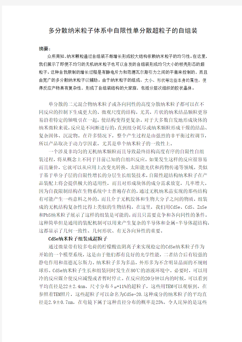
Figure 1 | 超粒子的电镜照片和尺寸分布.a–l,EM (a,d,g,j), TEM (b,e,h,k) 照片和
尺寸分布 (c,f,i,l) CdSe在不同反应时间获得的超粒子样品: 20min, CdSe-20(a–c);120 min,CdSe-30(d–f);1080 min,CdSe-40(g–i);2400 min,CdSe-50(j–l).m,CdSe超粒子制成
的胶体晶体的SEM照片.
单分散超粒子的核壳结构
有关超粒子结构的详细信息(Fig.2f,g,h)可以从小角X射线衍射获得(SAXS)。在小的q区域内(q<0.03?-1),在第一个最小区域一个明显的散射模型被观测到,CdSe-30,CdSe-40,CdSe-50的q分别是0.0236,0.0202,0.0182?-1.散射行为证实
了大型超粒子在溶液中的高单分散性。分散超粒子的相应直径数据可以从SAXS
得出,即37±0.4,46±0.5,49±0.5(补充表S1),分别TEM,SEM,DLS(Fig.1,Table 1)中的CdSe-30,CdSe-40,CdSe-50对应完好。
从Fig.2f中的拐点或者宽的衍射峰,人们可以计算超粒子内纳米粒子中心之间的距离。对于样品CdSe-30,CdSe-40,CdSe-50,它们的距离分别被估计为3.9
±0.2,5,5±0.2,6.8±0.4nm。那些估计的结果比(Table 1)平均直径d np稍微大
了1.5nm,这是由于纳米粒子外面包裹着两层有机柠檬酸离子。没有特定的峰指
明超粒子中的纳米粒子,与高的单分散性相吻合(Fig.1a)。
较大q区域对应于对散射模型有贡献的纳米粒子。在q>0,1?-1,没有观察到特殊的振荡,证明了纳米粒子的多分散性比它们呢的自组装更值得注意。这与从Table 1通过成像,散射和光谱技术获得的数据十分吻合。
我们注意到了干燥大体上不会改变超粒子(Fig.2f)。超粒子的尺寸相比于平均直径(CdSe-30的33±0.3,CdSe-40的40±0.4,CdSe-50的42±0.4)只减少
了不到10%(Fig.2f),这与超粒子内部的纳米粒子的密集堆积相吻合。干燥过程主要的是去除纳米粒子间隙内部的水分,很少导致超粒子内部的纳米粒子重新排列。
SAXS拟合曲线估计出在CdSe-50样品中平均一个单独的超粒子大约含有280
个纳米粒子(Fig.2g)。有趣的是,我们观察到了在堆积密集的超粒子内部的不
同梯度,越松散的核包裹着越紧密的纳米粒子外壳(Fig.2h)。在CdSe-50样品中,我们测到了一个5nm的壳层(Fig.2h),意味着壳层是5.4nm的纳米粒子的单分子
结构。
事实上,单分散的纳米粒子更容易自组装成多分散的、球形的超粒子,而不
是聚集或沉淀在平板上或二维材料,意味着纳米粒子凝结成块是热力学和自我限制的原因。考虑到柠檬酸盐高的负电性,假定静电作用是吸引纳米粒子的一个重要因素是合理的。实际上,有关超粒子形成过程中静电变化的研究表明:虽然最初这个值比较小(-5mv-0),但是随着超粒子的长大而增加,当超粒子自组装成致密结构时不变。我们因此推测超粒子致密性终止的原因是超粒子间以及纳米粒子和超粒子间的强静电斥力,它们最终会与范德瓦尔斯引力相互平衡。注意到超粒子上的静电电荷来自于单个的纳米粒子的固有电子、纳米粒子界面包括超粒子界面的电荷。对于纳米粒子表面电中性的设想是不成立的,因为纳米粒子的缺缝太小以至于不能建立合适的双电子层。
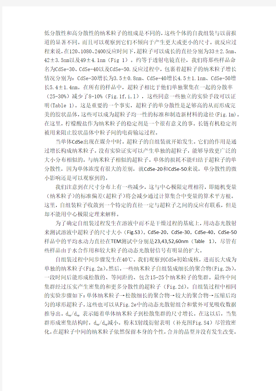
Figure 2 |中间阶段在40℃的形成超粒子和超粒子详细的结构表征。a-d,各个时间阶段的形成超粒子5分钟(a),9分钟(b),15分钟(c)和19分钟(d)。e,实验测得的d SP /d NP 和反应过程中的
电势。d SP /d NP 是通过DLS 和紫外可见光谱法测得,潜在电势是通过测量DLS 得到的。f ,
CdSe-30(1 )、CdSe-40(2)和CdSe-50 (3)超粒子的的SAXS 曲线。红色和蓝色的线条分别代表溶液和干样品,箭头为拐点的标志。g,CdSe-50数据在溶液中的测量数据(品红),并计算核壳超粒子模型(蓝色)的曲线。h,CdSe-50的核壳超粒子模型径向分布的子单元的数量。 多分散超粒子的形成机理
更多的研究通过电脑模拟被执行,因为电脑模拟可以考虑更多可能影响自组装的因素,例如:压力、纳米粒子的形状和多分散性等。虽然粒子尺寸在均一性和指示自组装上的影响在以前的文章中已经被报道了,但是有关纳米粒子组装成
均匀集群的模拟很少被执行。布朗动力学被用于模拟纳米粒子的系统,系统是一个三维立方结构,具有固定的体积和温度。一个电势为12-6的 Lennard-Jones 被用来模拟纳米粒子间的范德瓦尔斯引力,被屏蔽一定范围的库伦电势被用做静电作用。因为超粒子的负电荷会随着它们的尺寸增加而增加(Fig.2e ),纳米粒子和超粒子间的排斥作用的程度与超粒子的体积成比例。模型也规定超粒子核内的纳米粒子间的排斥程度和库伦屏蔽时间的长短比核外的大,因为超粒子内部的介质的介电常数比外部的小。
图3 |计算机仿真结果。a,四个阶段的自组装的超粒子与时间的关系。在最后阶段模拟的超粒子非球面性参数是0.014±0.006。b 、模拟的纳米粒子组装成超粒子的尺寸分布δ
NP simul
=20%,V NP =πσ3
/6是纳米粒子的平均体积。c 、粒子密度和从超粒子中心到攀附纳米颗粒的平均距离 d 、计算机模拟核壳CdSe 纳米粒子(蓝色)自组装成超粒子和包裹的金团簇(橙色)。e 、计算机模拟核壳CdSe 纳米粒子(蓝色)组装超粒子和成品金纳米棒(橙色)。
结果,研究表明在模拟过程中静电斥力强度不是常数,而是随着模拟的进行,纳
米粒子位置的不同而改变。基于所有的模拟数据,我们发现球形纳米粒子的δsimul=20%,相互作用仅仅包括静电斥力和范德瓦尔斯引力,描述的组装过程几乎NP
完美。
系统模拟的δNP simul=0-30%纳米粒子被发现和实验中有一样的组装过程:单个
纳米粒子→松散瘦长的聚集物→较大的聚集物→密集的均匀球形超粒子(Fig.3a
和Fig.2a-d)。最后阶段,单分散性超粒子在形状上与球形接近。模拟中一些带
有尖刺的超粒子(Fig.1与Fig.3a)被认为有可能是事实上纳米粒子组装成超粒
子后又继续长大,特别是超粒子的外壳。这个生长应该是非均匀的,归功于超粒
子外面更高的离子浓度,超粒子的外壳本身也有一个向外增长的趋势。一旦,超
粒子尺寸达到超粒子内部的纳米粒子与壳外最近的纳米粒子间静电斥力和范德
瓦尔斯引力相等的时候,聚合终止。重要的是,我们发现自限性行为只有当静电
斥力随着组装超粒子的体积单调增加时才会发生。否则,尽管有时间限制,纳米
粒子也会继续聚集。
聚集在Si表面的δNP simul=20%纳米粒子组装成超粒子在集群尺寸分布上表现
出尖峰(Fig.3b),在实验中可以重复观察到尺寸的单分散性。模拟的超粒子的
尺寸分布是与正常分布很吻合,标准偏差大概是7%(Fig.3b),这个结果与实验
中观察到的尺寸分布很接近(Table 1)。为了更进一步的确定超粒子是否是动力
学因素影响,我们增加了纳米粒子的密度,从0.01到0.1,这用来减少超粒子之
间的平均距离,观察到超粒子并没有融合成更大的超粒子,这可以确定动力学平
衡会不会起作用。当类似的模拟在不同纳米粒子几何形状、不同压力这些可变的
条件下,有一个很重要的发现:聚集的超粒子的几何形状不同于单分散的球形超
粒子。
我们的模拟也重复了从TEM和SAXS测量得到的超粒子内部的结构。超粒子的
核壳结构清晰的出现在δNP simul=20-30%的时(Fig.3c)。当δNP simul=20%时,模拟的
密集堆积超粒子核壳内的密度分别是是74±7%和89±5%;这些结果是从CdSe-50
得出的结果。超粒子内部强烈的静电斥力导致了超粒子松散堆积的核结构。另外,
值得注意的是纳米粒子的多分散性会导致纳米粒子的在超粒子内部的重新聚集,
例如,较小的纳米粒子聚集在外壳上,较大的纳米粒子聚集在核上。更进一步的,
我们观察到纳米粒子在壳上聚集的比在核上聚集的多,这可以解释为在壳哈桑堆
积的密度高。
压力会导致单分散性超粒子的形成,这是普适性的;这条途径应该用于其它
材料中各种不完美纳米粒子。实际上,很多Ⅱ-Ⅵ主族形成的超粒子可以生成半
导体,例如CdS、ZnSe;Ⅳ-Ⅵ主族形成的超粒子也可以生成半导体,例如PbS
(Fig.4a-c)。考虑到压力平衡,我们下一步的打算是围观已经存在的核形成类
似的自限性结构。事实上,这样的核可以通过有亲电能力粒子利用范德瓦尔斯引
Figure4 从其他材料组装成类似于超粒子。a-i,CdS(a),ZnSe(b)PbS(c)超粒子,
Au包围的CdS(d),Au包围的CdSe(e,f),Au核的CdS(g,h)和Au核的CdSe(i)核壳超粒子的TEM和SEM图像。j,k,高角环形暗场扫描TEM图像和Au包围的CdSe(j)和Au核的CdSe核壳超粒子(k)x -射线元素映射。 l,Au包围CdSe超粒子胶状晶体的SEM图像
力吸引溶液中的纳米粒子。我们注意到这种方法与常用的将相反电荷纳米胶质作为核粒子的方法是相反的。为了验证我们的假设,我们将用柠檬酸、在-39.4mv
电势下稳定的尺寸小于d SP的金纳米粒子在CdSe自组装成超粒子之前加入溶液中。我们切实的观察到单分子金核被CdSe纳米粒子包围的混合组装超粒子(Fig.4d-f)混合超粒子的核壳结构属性可以通过粒子的元素测量得出(Fig.4j)。超粒子是具有高分散性的,而且超粒子的形成可以归功于范德瓦尔斯引力和静电斥力的平衡,这可以从电脑模拟得出(Fig.3d)。用已经成型的核为制成更加复杂结构的超粒子提供了可能,而且能够更容易的制出多种几何结构和功能的超结构。制成的金属半导体超粒子能进一步自组装成胶状晶体,具有独一无二的分层次的更多的应用(Fig.4l)。进一步的与传统的核壳结构的量子点作比较,可以得出复杂的核壳结构超粒子在制备方法、特性、结构、潜在应用都和核壳结构的量子点不同。
无机超粒子与毒性粒子
我们还发现各向异性金纳米棒倾向于形成单分散圆柱形超粒子,这个结果在实验中(Fig.4g-ik)和模拟中(Fig.3e)都可以看到。引人注意地是,无论球形还是棒形的核壳结构超粒子都类似于病毒外壳的生物超结构,这种结构中蛋白质是外壳包围这DNA和RNA核。例如,豇豆花叶病毒的是球形的,用60种蛋白质组装成二十面体的超粒子,而流感、狂犬病和其他病毒是仅仅是扩展的,或者相似大小或组成单元数类似于棒状的超粒子。注意到一些病毒没有表现出完美的几何结构,比如HIV病毒。我们的工作表明,纳米粒子可以组装成类似病毒一样复杂的结构,虽然没有功能性各异的蛋白质和生物分子,但是可以用库仑力和范德瓦尔斯力的平衡来取代。超粒子组装能够被更复杂的纳米级系统工程实验所利用,包括可重构组装,联合他们的性能,在硅表面上测试;分层次的组装成胶状超粒子晶体将会打开简单制作大规模复杂材料和器件的大门。
(文档含英文原文和中文翻译) 中英文对照外文翻译 基于拉格朗日乘数法的框架结构合理线刚度比的研究 【摘要】框架结构是一种常见的多层高层建筑结构;列的合理线刚度比研究是框架结构优化设计中的一个重要方面。本论文研究合理线刚度比时,框架梁、柱的
侧移刚度根据拉格朗日乘数法结构优化的理论和在框架梁、柱的总物质的量一定的前提下,取得最高值。与传统的估计方法和试算梁柱截面尺寸不同,梁、柱的合理的截面尺寸可以在初步设计阶段由派生的公式计算。这种方法不仅作为计算框架梁、柱的截面尺寸基础,确认初步设计阶,而且也被用做类似的结构梁柱合理线刚度比研究的参考。此外,在调整帧梁、柱的截面尺寸的方法的基础上,降低柱的轴向的压缩比,从而达到剪切压缩比和提高结构的延展性。 【关键词】拉格朗日数乘法框架结构刚度比截面尺寸 1 引言 在混凝土框架结构初步设计的期间,通常,框架梁截面高度通过跨度来估算,和截面宽度根据高宽比估算; 框架柱的截面尺寸是根据柱轴压缩的支持柱的面积的比率估算[1]。然而,在估计过程中,初步设计阶段中的一个重要的链,未考虑到柱侧移刚度的影响[2]。列侧移刚度越大,结构层间位的刚度越大,剪切型框架结构的层间位移将越较小。所以,总结构越小的侧向位移将减少地震灾害[3] 所造成的损失。论文的核心是如何得到列侧移刚度的最大值。 同时,列侧移刚度的值与框架梁-柱线刚度直接相关。本论文的目的是为了得到一个合理的框架梁 - 柱的线刚度比,在某个控制范围内获得列侧移刚度的最大值。 计算列横向位移的方法有两种方法:刚度拐点点法和修改拐点法。拐点的方法假定关节的旋转角度为0(当梁柱线性刚度比是大于或等于3时,柱的上端和下端的关节的旋转角度可以取为0,因为它实际上是相当小),即梁的弯曲刚性被视为无穷大。拐点的方法主要是应用于具有比较少层的框架结构。但对于多层、高层框架结构,增加柱截面会导致梁柱线刚度比小于3,在水平荷载作用下,框架结构的所有关节的旋转角度的横向位移会发生不可忽视。因此,一位日本教授武藤提出修改拐点法[4],即D-值方法。本文采用D-值列侧移刚度的计算法,因为它着重于多层、高层框架结构。 少数在国内外对框架梁柱合理线刚度比的研究,只有梁七黹,源于列侧移刚度的计算方法,比D-值法更加应用广泛;申得氏指出在多层、高层框架结构的柱侧向刚度计算中存在的问题,补充和修改底部和顶部层的列侧向刚度计算公式;
理工学院 毕业设计外文资料翻译 专业:计算机科学与技术 姓名:马艳丽 学号: 12L0752218 外文出处:The Design and Implementation of 3D Electronic Map of Campus Based on WEBGIS 附件: 1.外文资料翻译译文;2.外文原文。
附件1:外文资料翻译译文 基于WebGIS的校园三维电子地图的设计与实现 一.导言 如今,数字化和信息化是当今时代的主题。随着信息革命和计算机科学的发展,计算机技术已经渗透到科学的各个领域,并引起了许多革命性的变化,在这些科目,古代制图学也不例外。随着技术和文化的不断进步,地图变化的形式和内容也随之更新。在计算机图形学中,地理信息系统(GIS)不断应用到Web,制作和演示的传统方式经历了巨大的变化,由于先进的信息技术的发展,地图的应用已经大大延长。在这些情况下,绘图将面临广阔的发展前景。电子地图是随之应运而生的产品之一。随着计算机技术,计算机图形学理论,遥感技术,航空摄影测量技术和其他相关技术的飞速发展。用户需要的三维可视化,动态的交互性和展示自己的各种地理相关的数据处理和分析,如此多的关注应支付的研究三维地图。东北石油大学及其周边地区的基础上本文设计并建立三维电子地图。 二.系统设计 基于WebGIS的校园三维电子地图系统的具有普通地图的一般特性。通过按键盘上的箭头键(上,下,左,右),可以使地图向相应的方向移动。通过拖动鼠标,可以查看感兴趣的任何一个地方。使用鼠标滚轮,可以控制地图的大小,根据用户的需求来查看不同缩放级别的地图。在地图的左下角会显示当前鼠标的坐标。在一个div层,我们描绘了一个新建筑物的热点,这层可以根据不同的地图图层的显示,它也可以自动调整。通过点击热点,它可以显示热点的具体信息。也可以输入到查询的信息,根据自己的需要,并得到一些相关的信息。此外,通过点击鼠标,人们可以选择检查的三维地图和卫星地图。 主要功能包括: ?用户信息管理:检查用户名和密码,根据权限设置级别的认证,允许不同权限的用户通过互联网登录系统。 ?位置信息查询:系统可以为用户提供模糊查询和快速定位。
附录 科技译文: Numerical Control Numerical Control(NC) is a method of controlling the movements of machineComponents by directly inserting coded instructions in the form of numerical data(numbers and data ) into the system.The system automatically interprets these data and converts to output signals. These signals ,in turn control various machine components ,such as turning spindles on and off ,changing tools,moving the work piece or the tools along specific paths,and turning cutting fluits on and off. In order to appreciate the importer of numerical control of machines ,let’s briefly review how a process such as machining has been carried out traditionally .After studying the working drawing of a part, the operator sets up the appropriate process parameters(such as cutting speed ,feed,depth of cut,cutting fluid ,and so on),determines the sequence of operations to be performed,clamps the work piece in a workholding device such as chuck or collet ,and proceeds to make the part .Depending on part shape and the dimensional accuracy specified ,this approach usually requires skilled
框架结构毕业设计任务书和指导书 1 2020年4月19日
毕业设计基本要求 1目的 (1)综合运用所学专业理论知识与设计技能,处理建筑设计中有关方针、政策、功能、经济、安全、美观等方面的问题。解决总体、单体、空间等关系,以创造富有时代气息的优美建筑形象与环境。依据建筑设计完成结构体系的布置、结构在各种荷载工况下的计算、构造和施工图。 (2)掌握一般建筑工程的设计思路,进而举一反三熟悉有关建筑工程的设计、施工、预算等建设过程。为即将走上工作岗位奠定基础。 (3)学以致用,学习科学技术和技能的目的是应用。一个工程师在设计、建设实际工程中应具备的知识,都是我们在毕业设计中应予以加强的。因此深切领悟总体概念设计、掌握具体理论设计和实际工程技术处理措施的结合作为重点来训练。 (4)树立正确的设计思想,全面对待建筑与结构的关系, 2 2020年4月19日
培养勤奋、严谨、认真的工作作风及分析解决一般工程技术问题的能力。 (5)掌握调查研究、理论联系实际的学习方法,养成既能独立思考,又能相互配合密切合作的工作态度。 (6)使学生对一般工业与民用建筑的土建设计的内容和构成有比较全面的了解,并熟悉有关设计标准、规范、手册和工具书,增强毕业后到生产第一线工作的适应能力。 2成果形式及要求 (1)计算书和说明书: 字数应不少于1万字,书写要工整,字迹要清楚,可采用计算机打印。计算书内容要阐明设计依据或标准,方案构思、特点、必要的经济指标,结构选型、构造处理、材料特点及计算上的主要问题,还应包括结构计算全过程,计算要正确、完整、思路清晰、简图明了。计算书格式:应严格按照毕业设计手册中的要求。 (2)图纸: 3 2020年4月19日
附录 INTEGRATION OF MACHINERY (From ELECTRICAL AND MACHINERY INDUSTRY)ABSTRACT Machinery was the modern science and technology development inevitable result, this article has summarized the integration of machinery technology basic outline and the development background .Summarized the domestic and foreign integration of machinery technology present situation, has analyzed the integration of machinery technology trend of development. Key word:integration of machinery ,technology,present situation ,product t,echnique of manufacture ,trend of development 0. Introduction modern science and technology unceasing development, impelled different discipline intersecting enormously with the seepage, has caused the project domain technological revolution and the transformation .In mechanical engineering domain, because the microelectronic technology and the computer technology rapid development and forms to the mechanical industry seepage the integration of machinery, caused the mechanical industry the technical structure, the product organization, the function and the constitution, the production method and the management system has had the huge change, caused the industrial production to enter into “the integration of machinery” by “the machinery electrification” for the characteristic development phase. 1. Integration of machinery outline integration of machinery is refers in the organization new owner function, the power function, in the information processing function and the control function introduces the electronic technology, unifies the system the mechanism and the computerization design and the software which constitutes always to call. The integration of machinery development also has become one to have until now own system new discipline, not only develops along with the science and technology, but also entrusts with the new content .But its basic characteristic may summarize is: The integration of machinery is embarks from the system viewpoint, synthesis community technologies and so on utilization mechanical technology, microelectronic technology, automatic control technology,
多层混凝土框架结构设计 1.前言 随着社会的发展,钢筋混凝土框架结构的建筑物越来越普遍.由于钢筋混凝土结构与砌体结构相比较具有承载力大、结构自重轻、抗震性能好、建造的工业化程度高等优点;与钢结构相比又具有造价低、材料来源广泛、耐火性好、结构刚度大、使用维修费用低等优点。因此,在我国钢筋混凝土结构是多层框架最常用的结构型式。近年来,世界各地的钢筋混凝土多层框架结构的发展很快,应用很多。 一般框架结构是由楼板、梁、柱及基础4种承重构件组成的,由主梁、柱与基础构成平面框架,各平面框架再由连续梁连接起来而形成的空间结构体系。文献[1]认为,在合理的高度和层数的情况下,框架结构能够提供较大的建筑空间,其平面布置比较的灵活,可适合多种工艺与使用功能的要求。 多层钢筋混凝土框架结构设计可以分为四个阶段:一是方案设计,二是结构分析,三是构件设计,四是绘施工图。结构分析和构件设计是结构设计中的计算阶段,在现代,已由电子计算机承担这一工作,常采用PKPM建模计算。但是,结构的计算并不能代替结构的设计。文献[2]中认为:良好的结构设计的重要前提,应该是合理组织与综合解决结构的传力系统、传力方式,良好的结构方案是良好结构设计的重要前提。2.关于框架结构设计文献回顾 2.1框架结构的优缺点 框架结构体系是由横梁与柱子连接而成.梁柱连接处(称为节点)一般为刚性连接,有时为便于施工和其他构造要求,也可以将部分节点做成铰接或者半铰接.柱支座一般为固定支座,必要时也可以设计成铰支座.框架结构可以分为现浇整体式,装配式,现浇装配式. 文献[3]中提到:框架结构的布置灵活,容易满足建筑功能和生工艺的多种要求.同时,经过合理设计,框架结构可以具有较好的延性和抗震性能.但是,框架结构承受水平力(如风荷载和水平地震作用)的能力较小.当层树较多或水平力较大时,水平位移较大,在强烈地震作用下往往由于变形过大而引起非结构构件(如填充墙)的破坏.因此,为了满足承载力和侧向刚度的要求,柱子的截面往往较大,既耗费建筑材料,又减少使用面积.这就使框架结构的建筑高度受到一定的限制.目前,框架结构一般用于多层建筑和不考虑抗震设防,层数较少的的高层建筑(比如,层数为10层或高度为30米以下) 2.3框架结构的布置 多层框架结构的平面布置形式非常的灵活,文献[4]中将框架结构按照承重方式的不同分为以下三类:(1)横向框架承重方案,以框架横梁作为楼盖的主梁,楼面荷载主要由横向框架承担.由于横向框架数往往较少,主梁沿横向布置有利于增强房屋的横向刚度.同时,主梁沿横向布置还有利于建筑物的通风和采光.但由于主梁截面尺寸较大,当房屋需要大空间时,净空较小,且不利于布置纵向管道. (2)纵向框架承重方案以框架纵梁作为楼盖的主梁,楼面荷载由框架纵梁承担.由于横梁截面尺寸较小,有
72页 Machine Tools Objectived. Machine tools are the main engines of the manufacturing industry. This chapter covers a few of the details that are common to all classes of machine tools discussed in this book. After completing the chapter, the reader will be able to >understand the classification of the various machine tools used in manufacturing industries. >identify the differences between generating and forming of surfaces. > identify various methods used to generate different types of surfaces. >distinguish between the different accuracies and surface finishes that are achievable with different machine tools. >understand the different components of the machine tools and their functions. >learn about the different support structures used in the machine tools. >understand the various actuation systems that are useful to generate the required surfaces. >Learn the different types of guideways used in the machine tools. >understand the work holding requirements. 3.1 INTRODUCTION The earliest known machine tools are the Egyptian foot-operated lathes.
毕业设计(论文) 外文翻译 题目西安市水源工程中的 水电站设计 专业水利水电工程 班级 学生 指导教师 2016年
研究钢弧形闸门的动态稳定性 牛志国 河海大学水利水电工程学院,中国南京,邮编210098 nzg_197901@https://www.doczj.com/doc/695983304.html,,niuzhiguo@https://www.doczj.com/doc/695983304.html, 李同春 河海大学水利水电工程学院,中国南京,邮编210098 ltchhu@https://www.doczj.com/doc/695983304.html, 摘要 由于钢弧形闸门的结构特征和弹力,调查对参数共振的弧形闸门的臂一直是研究领域的热点话题弧形弧形闸门的动力稳定性。在这个论文中,简化空间框架作为分析模型,根据弹性体薄壁结构的扰动方程和梁单元模型和薄壁结构的梁单元模型,动态不稳定区域的弧形闸门可以通过有限元的方法,应用有限元的方法计算动态不稳定性的主要区域的弧形弧形闸门工作。此外,结合物理和数值模型,对识别新方法的参数共振钢弧形闸门提出了调查,本文不仅是重要的改进弧形闸门的参数振动的计算方法,但也为进一步研究弧形弧形闸门结构的动态稳定性打下了坚实的基础。 简介 低举升力,没有门槽,好流型,和操作方便等优点,使钢弧形闸门已经广泛应用于水工建筑物。弧形闸门的结构特点是液压完全作用于弧形闸门,通过门叶和主大梁,所以弧形闸门臂是主要的组件确保弧形闸门安全操作。如果周期性轴向载荷作用于手臂,手臂的不稳定是在一定条件下可能发生。调查指出:在弧形闸门的20次事故中,除了极特殊的破坏情况下,弧形闸门的破坏的原因是弧形闸门臂的不稳定;此外,明显的动态作用下发生破坏。例如:张山闸,位于中国的江苏省,包括36个弧形闸门。当一个弧形闸门打开放水时,门被破坏了,而其他弧形闸门则关闭,受到静态静水压力仍然是一样的,很明显,一个动态的加载是造成的弧形闸门破坏一个主要因素。因此弧形闸门臂的动态不稳定是造成弧形闸门(特别是低水头的弧形闸门)破坏的主要原是毫无疑问。
本科毕业论文(设计) 外文翻译 学院:机电工程学院 专业:机械工程及自动化 姓名:高峰 指导教师:李延胜 2011年05 月10日 教育部办公厅 Failure Analysis,Dimensional Determination And
Analysis,Applications Of Cams INTRODUCTION It is absolutely essential that a design engineer know how and why parts fail so that reliable machines that require minimum maintenance can be designed.Sometimes a failure can be serious,such as when a tire blows out on an automobile traveling at high speed.On the other hand,a failure may be no more than a nuisance.An example is the loosening of the radiator hose in an automobile cooling system.The consequence of this latter failure is usually the loss of some radiator coolant,a condition that is readily detected and corrected.The type of load a part absorbs is just as significant as the magnitude.Generally speaking,dynamic loads with direction reversals cause greater difficulty than static loads,and therefore,fatigue strength must be considered.Another concern is whether the material is ductile or brittle.For example,brittle materials are considered to be unacceptable where fatigue is involved. Many people mistakingly interpret the word failure to mean the actual breakage of a part.However,a design engineer must consider a broader understanding of what appreciable deformation occurs.A ductile material,however will deform a large amount prior to rupture.Excessive deformation,without fracture,may cause a machine to fail because the deformed part interferes with a moving second part.Therefore,a part fails(even if it has not physically broken)whenever it no longer fulfills its required function.Sometimes failure may be due to abnormal friction or vibration between two mating parts.Failure also may be due to a phenomenon called creep,which is the plastic flow of a material under load at elevated temperatures.In addition,the actual shape of a part may be responsible for failure.For example,stress concentrations due to sudden changes in contour must be taken into account.Evaluation of stress considerations is especially important when there are dynamic loads with direction reversals and the material is not very ductile. In general,the design engineer must consider all possible modes of failure,which include the following. ——Stress ——Deformation ——Wear ——Corrosion ——Vibration ——Environmental damage ——Loosening of fastening devices
英文翻译 题目: 通过分析变压器中溶解气体而进行故障诊断的专家系统 姓名: 宋日成 学院: 工学院 专业: 自动化 班级: 自动化112 班学号: 32211218 指导教师: 陆静职称: 讲师 2015年3月14日 南京农业大学教务处制
An Expert System for Transformer Fault Diagnosis Using Dissolved Gas Analysis W. S. Chan ·Y. L. Xu ·X. L. Ding ·W. J. Dai Received: 9 November 2005 / Accepted: 11 August 2006 / Published online: 7 September 2006? Springer-Verlag 2006 Abstract In order to automate the transformer fault diagnosis, improve the accuracy of judgment, the introduction of artificial intelligence expert system fault diagnosis. The system is based on fuzzy reasoning confidence by observing the information, the use of knowledge to reach a conclusion. Test proved this method reduces the randomness of judgment, improved diagnosis. Keywords:Expert System Transformer Troubleshooting 1 Introduction The power transformer is a major apparatus in a power system, and its correct functioning is vital to system operations. In order to minimize system outages,many devices have evolved to monitor the serviceability of power transformers. These devices, such as, Buchholz relays or differential relays, respond only to a severe power failure requiring immediate removal of the transformer from service, in which case, outages are inevitable. Thus, preventive techniques for early detection faults to avoid outages would be valuable. In this way, analysis of the mixture of the faulty gases dissolved in insulation oil of power transformer has received worldwide recognition as an effective method for the detection of incipient faults. Many researchers and electrical utilities have reported on their experience and developed interpretative criteria on the basis of DGA. However, criteria tend to vary from utility to utility. Each approach has limitations and none of them has a firm mathematical description. Therefore, transformer diagnosis is still in the heuristic stage. For this reason, knowledge-based programming is a suitable approach to implement in such a diagnostic problem. Based on the interpretation of DGA, a prototype of an expert system for diagnosis of suspected transformer faults and their maintenance procedures is proposed. The significant source in this knowledge base is the gas ratio method. Some limitations of this approach are overcome by incorporating the diagnostic procedure and the synthetic expertise method. Furthermore, data bases adopted from TPCS gas records of transformers are incorporated into the expert system to increase the practical performance. Uncertainty of diagnosis is managed by using fuzzy set concepts. This expert system is constructed with rule based knowledge representation, since it can be expressed by experts. The expert system building tool, Knowledge Engineering System (KES), is used in the development of the knowledge system
xxxxxxxxx 毕业设计(论文)外文文献翻译 (本科学生用) 题目:Poduct Line Engineering: The State of the Practice 生产线工程:实践的形态 学生姓名:学号: 学部(系): 专业年级: 指导教师:职称或学位: 2011年3月10日
外文文献翻译(译成中文1000字左右): 【主要阅读文献不少于5篇,译文后附注文献信息,包括:作者、书名(或论文题目)、出版社(或刊物名称)、出版时间(或刊号)、页码。提供所译外文资料附件(印刷类含封面、封底、目录、翻译部分的复印件等,网站类的请附网址及原文】 Requirements engineering practices A precise requirements engineering process— a main driver for successful software development —is even more important for product line engineering. Usually, the product line’s scope addresses various domains simultaneously. This makes requirements engineering more complex. Furthermore, SPL development involves more tasks than single-product development. Many product line requirements are complex, interlinked, and divided into common and product-specific requirements. So, several requirements engineering practices are important specifically in SPL development: ? Domain identification and modeling, as well as commonalities and variations across product instances Separate specification and verification for platform and product requirements ? Management of integrating future requirements into the platform and products ? Identification, modeling, and management of requirement dependencies The first two practices are specific to SPL engineering. The latter two are common to software development but have much higher importance for SPLs. Issues with performing these additional activities can severely affect the product line’s long-term success. During the investigation, we found that most organizations today apply organizational and procedural measures to master these challenges. The applicability of more formal requirements engineering techniques and tools appeared rather limited, partly because such techniques are not yet designed to cope with product line evelopment’s inherent complexities. The investigation determined that the following three SPL requirements engineering practices were most important to SPL success. Domain analysis and domain description. Before starting SPL development, organizations should perform a thorough domain analysis. A well-understood domain is a prerequisite for defining a suitable scope for the product line. It’s the foundation for efficiently identifying and distinguishing platform and product requirements. Among the five participants in our investigation, three explicitly modeled the product line requirements. The others used experienced architects and domain experts to develop the SPL core assets without extensive requirements elicitation. Two organizations from the first group established a continuous requirements management that maintained links between product line and product instance requirements. The three other organizations managed their core assets’ evolution using change management procedures and versioning concepts. Their business did not force them to maintain more detailed links between the requirements on core assets and product instances. The impact of architectural decisions on requirements negotiations. A stable but flexible architecture is important for SPL development. However, focusing SPL evolution too much on architectural issues will lead to shallow or even incorrect specifications. It can cause core assets to ignore important SPL requirements so that the core assets lose relevance for SPL development. Organizations can avoid this problem by establishing clear responsibilities for requirements management in addition to architectural roles. The work group participants reported that a suitable organizational tool for balancing requirements and architecture is roundtable meetings in which requirements engineers,
沈阳工业大学工程学院 毕业设计(论文)外文翻译 毕业设计(论文)题目:工具盒盖注塑模具设计 外文题目:Friction , Lubrication of Bearing 译文题目:轴承的摩擦与润滑 系(部):机械系 专业班级:机械设计制造及其自动化0801 学生姓名:王宝帅 指导教师:魏晓波 2010年10 月15 日
外文文献原文: Friction , Lubrication of Bearing In many of the problem thus far , the student has been asked to disregard or neglect friction . Actually , friction is present to some degree whenever two parts are in contact and move on each other. The term friction refers to the resistance of two or more parts to movement. Friction is harmful or valuable depending upon where it occurs. friction is necessary for fastening devices such as screws and rivets which depend upon friction to hold the fastener and the parts together. Belt drivers, brakes, and tires are additional applications where friction is necessary. The friction of moving parts in a machine is harmful because it reduces the mechanical advantage of the device. The heat produced by friction is lost energy because no work takes place. Also , greater power is required to overcome the increased friction. Heat is destructive in that it causes expansion. Expansion may cause a bearing or sliding surface to fit tighter. If a great enough pressure builds up because made from low temperature materials may melt. There are three types of friction which must be overcome in moving parts: (1)starting, (2)sliding, and(3)rolling. Starting friction is the friction between two solids that tend to resist movement. When two parts are at a state of rest, the surface irregularities of both parts tend to interlock and form a wedging action. To produce motion in these parts, the wedge-shaped peaks and valleys of the stationary surfaces must be made to slide out and over each other. The rougher the two surfaces, the greater is starting friction resulting from their movement . Since there is usually no fixed pattern between the peaks and valleys of two mating parts, the irregularities do not interlock once the parts are in motion but slide over each other. The friction of the two surfaces is known as sliding friction. As shown in figure ,starting friction is always greater than sliding friction . Rolling friction occurs when roller devces are subjected to tremendous stress which cause the parts to change shape or deform. Under these conditions, the material in front of a roller tends to pile up and forces the object to roll slightly uphill. This changing of shape , known as deformation, causes a movement of molecules. As a result ,heat is produced from the added energy required to keep the parts turning and overcome friction. The friction caused by the wedging action of surface irregularities can be overcome