外文原文:
Programmable designed for electro-pneumatic systems controller Abstract
This project deals with the study of electro-pneumatic systems and The programmable controller that provides an effective and easy way to Control the sequence of the pneumatic actuators movement and the states of pneumatic system. The project of a specific controller for pneumatic applications join the study of automation design and the control processing of pneumatic systems with the electronic design based on microcontrollers to implement the resources of the controller.
1.Introduction
The automation systems that use electro-pneumatic technology are formed mainly by three kinds of elements: actuators or motors,sensors or buttons and control elements like valves. Nowadays,mostof the control elements used to execute the logic of the system were substituted by the Programmable Logic Controller(PLC). Sensors and switches are plugged as inputs and the direct cntrol valves for the actuators are plugged as outputs. An internal program executes all the logic necessary to the sequence of the movements,simulates other components like counter,timer and control the status of the system.
With the use of the PLC,the project wins agility,because it is possible to create and simulate the aystem as many times as nended .therefore,time can be saved,risk of mistakes reduced and complexity can be increased using the same elements.
A conventional PLC,this is possible to find on the market from many companies,offers many resources to control not only pneumatic systems,but all kinds of system that uses electrical comonents .the PLC can be very versatile and robust be applied in many kinds of application in the industry or even security system and automation of buildings.
Because of those characteristics,in some applications the PLC offers to much resources that are not even used to control the system,electro-pneumatic system is one of this kind of application.The use of PLC,especially for small Size systems,can be very expensive for the automation project.An alterative in this case is to create a specific controller that can offer the exactly size and resources that the project nends.this can be made using micrcontrollers as the base of this controller.
The controller,based on microcontroller,can be very specific and adapted to only
One kind of machine or it can work as a generic controller that can be programmed.As a usual PLC and work with logic that can be changed. All the characteristics depend on what is needed and how much experience the designer has with developing an electronic circuit and firmware for microcontroller.But the main advantage of design the controller with the microcontroller is that the designer has the total knowledge of his controller,which makes it possible to control the size of the controller,change the complexity and the application of it.It means that the project gets more independence from other companies,but at the same time the responsibility of the control of the system stays at the designer hands.
2.Electro-pneumatic system
On automation system one can find three basic components mentioned before,plus A logic circuit that controls the system. An adequate technique is needed to project the logic circuit and integrate all the necessary components to execute the sequence of movements properly.For asimple direct sequence of movement an intuitive method can be used[1,5],but for indirect or more complex sequences the intuition can generate a very complicated circuit and signal mistakes.It is necessary to use another method that can save time of the project,make a clean circuit, can eliminate occasional signal overlapping and redundant circuits.
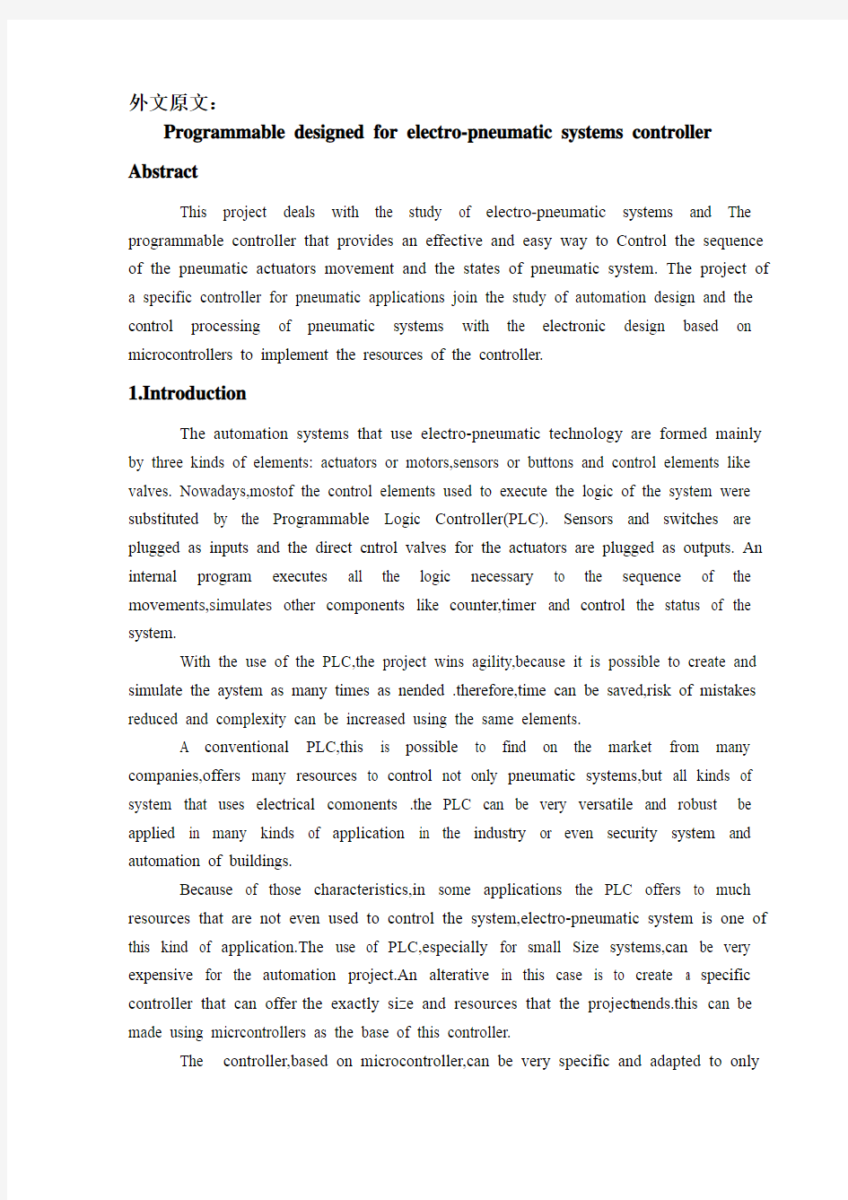
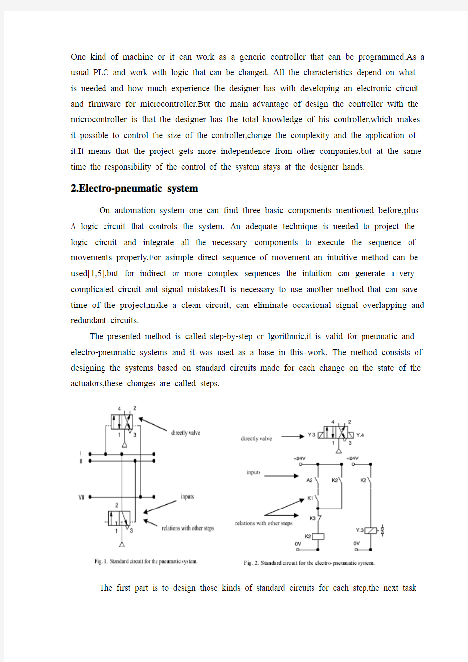
The presented method is called step-by-step or lgorithmic,it is valid for pneumatic and electro-pneumatic systems and it was used as a base in this work. The method consists of designing the systems based on standard circuits made for each change on the state of the actuators,these changes are called steps.
The first part is to design those kinds of standard circuits for each step,the next task
is to link the standard circuits and the last part is to connect the control elements that receive signals from sensors, switches and the previous movements,and give the air or electricity to the supply lines of each step.In Figs.(1) and (2) the standard circuits are drawn for pneumatic and electro-pneumatic system.It is possible to see the relations with the previous and the next steps.
3.the method applied inside the controller
The result of the method presented before is a sequence of movements of the actuator that is well defined by stepas .It means that each change on the position of the actuators is a new state of the system and the transition between states is calld step.
The standard circuit described before helps the designer to define the states of the systems and to define the condition to each change between the states. In the end of the design,the system is defined by a sequence that never chances and states that have the inputs and the outputs well defined.The inputs are the condition for the transition and the outputs are the result of the transition.
All the configuration of those steps stays inside of the microcontroller and is executed the same way it was designed. The sequence of strings are programmed inside the controller with 5 bytes;each string has the configuration of one step of the process There are two bytes for the inputs,one byte for the outputs and two more for the other configurations and auxiliary functions of the step.After programming,this sequence of strings is saved inside of a non-volatil Memory of the microcontroller,so they can be read and executed.
The controller task is not to work in the same way as a conventional PLC,but the purpose of it is to be an example of a versatile controller that is design for an specific area.A conventional PLC process the control of the system using a cycle where it makes an image of the inputs,execute all the conditions defined by the configuration programmed inside,and then update the state of the outputs. This controller works in a different way,where it read the configuration of the step,wait the condition of inputs to be satisfied,then update the state or the outputs and after that jump to the next step and start the process again.
It can generate some limitations,as the fact that this controller cannot execute, inside the program,movements that must be repeated for sometime,but this problem can be solved with some external logic components.Another limitation is that the controller cannot be applied on systems that have no sequence.These limitations are a characteristic of the system that must be analyzed for each application.
4.Characteristics of the controller
The controller is based on the MICROCHIP microcontroller PICF877[6,7]with 40 pins,and it has all the resources neened for this project.it has enough pins for all the comonents,serial communication implemented in circuit,EEPROM memory to save all the configuration of the system and tne sequence of steps.For the execution of the main program,it offers comlete resources as timers and interruptions.
The list of resources of the controller was created to explore all the capacity of the microcontroller to make it as complete as possible.during the step,the program chooses how to use the resources reading the configuration string of the step.this string has two bytes for digital inputs,one used as a mask and the other one used as a value expeced.one byte is used to configure the output or time-out.the EEPROM memory inside is 256 bytes length that is enough to save the string of the steps,with this characteristic it is possoble to save between 48 steps(table1).
The controller(FIG.3)has also a display and some buttons that are used with an interactive menu to program the sequence of steps and other configurations.
4.1. Interaction components
For the real application the conteoller must have some elements to interact with the final user and to offer a complete monitoring of the system resources that are available to the designer while creating the logic control of the pneumatic system(Fig.3).
●Intercative mode of work;function available on the main program for didactic
purposes,the use gives the signal to execute the step.
●LCD display,which shows the status of the system,values of inputs,outputs,timer and
statistics of the sequence execution.
●Beep to give important alerts,stop ,start and emergency.
●Led to show power on and others to show the state of iputs and outputs.
4.2. security
To make the final application works property ,a correct configuration to execute the steps in the right way is needed,but more then that it must offer solutions in case of bad functioning or problems in the execution of the sequence.The controller offers the possibility to configure two internalvirtual circuits that work in parallel to the principal.These two circuits can be used as emergency or reset buttons and can return the system to a certain state at any time.There are two inputs that work with interruption to get an immediate access to these functions.It is possible to configure the position,the buttons
and the value of time-out of the system.
4.3. User interface
The sequence of strings can be programmed using the interface elements os the controller.A computer interface can be used to generate the user program easily.With a good documentation the final user can use the interface to configure the strings of bytes that define the steps of the sequence.But it is possible to create a program with visual resources that works as a translator to the user, it changes his work to the values that the controller understands.
To implement the communication between the computer interface and the controller a simple protocol with check sum and number of bytes is the minimum requirementas to guarantee the integrity of the data.
4.4.Firmware
The main loop works by reading the strings of the steps from the EEPROM memory that has all the information about the steps.In each step,the status of the system is saved on the memory and it is shown on the display too.Depending of the user configuration,it can use the interruption to work with the emergency circuit or time-out to keep the system safety .In Fig.4,a block diagram of micro controller main program is presented.
5.Example of electro-pneumatic system
The system is not a representation of a specific machine,but it is made with some common novements and components found in a real one.The system is composed of four actuators.The actuators A,B and C are double acting and D-single acting.Actuator A advances and stays in specified position till the end of the cycle,it could work fixing an object to the next action for example(Fig.5),it is the first step.When a reaches the end position,actuator C starts his work together with B,making as many cycles as possible during the advancing of B.It depends on how fast actuator B is advancing;the speed is regulated by a flowing control valve.It was the second step.B and C are examples of actuators working together,while B pushes an object slowly,C repeats ins work for some time
When B reaches the final position,C stops immediately its cycle and comes back to the initial position.The actuator D is a single acting one with spring return and works together with the back of C,it is the third step.D works making very fast forward and backward movement,just one time.Its backward movement is the fourth step.D could be a
tool to make a hole on the object.
When Dreaches the initial position,A and B return too,it is the fifth step.Fig.6 show the first part of the designing process where all the movements of each step should be defined[2]. (A+)means that the actuator A moves to the advanced position and (A?) to the initial position. The movements that happen at the same time are joined
together in the same step. Th system has five steps.These two representations of the system.
(Figs.5 and 6)together are enough to describe correctly all the sequence. With them is possible to design the whole control circuit with the necessary logic components.But till this time,it is not a complete system,because it is missing some auxiliary elements that are not included in this draws because they work in parallel with the main sequence.
These auxiliary elements give more function to the circuit and are very important to the final application,the most important of them is the parallel circuit linked with all the others steps.That circuit should be able to stop the sequence at any time and change the state of the actuators to a specific position.This kind of circuit can be used as a reset or emergency buttons.
The next figs.7 and 8 show the result of using the method without the controller.Theese pictures are the electric diagram of the control circuit of the example,including sensors,buttons and the coils of the electrical valves.
The auxiliary elements are included,like the automatic/manual switcher that permit a
continuous work and two start buttons that make the qperator of a machine use their two hands to start the process,reducing the ridk of accidents.
6.Changing the example to a user program
In the previous chapter ,the electro-pneumatic circuits were presented,used to begin the study of the requires to control a system that work with steps and must offer all the functional elements to be used in a real application .but,as explained above,using a PLC or this specific conteoller ,the control becomes easier and the complexity can be increase also.
With the time diagram,the step sequence and the elements of the system described in Table 2 and Figs.5 and 6 it is possible to the new programming allows that the configuration of the steps be separated,like described by the method .The sequence is defined by itself and the steps are described only by the inputs and outputs for each step.
Table 5 shows how the user program is saved inside the controller, this is the program that describes the control of the exanple shown before.
The sequence can be defined by 25 bytes these bytes can be divded in five strings with 5 bytes each that define each step of the sequence (Figs.9 and 10)
7.conclusion
The controller developed for this work (Fig .11)shows that it is possible to create a very useful programmable controller based on microcontroller. External memories that the miscrocontroller offers inside Outside the microcotroller , there ara only components to implement the outputs , inputs , analoginputs , display for the interface and the serial communication.
Using only the internal memory , it is possbel to control a pneumatic system that has a sequence with 48 stsps if all the resources for all steps ara used , but it is possble to reach sixty steps in the case of a simpler system . The programming of the controller dose not use PLC languages , but a configuration that is simple and intuitive , With electro-pneumatic system , the programming follows the same technique that was used before to design the system , but here the designer workes directly with the states or steps of the system.
With a very simple machine language the designer can define all the configuration of the step using four or five bytes.It depends only on his experience to use all the resources of the controller.The controller task is not to work in the same way as a commercial PLC but the purpose of it is to be an example of a versatile controller that is designed for a specific area.Because of that ,it is not possible to say which one works better ;the system made with microcontroller is an alternative that works in a simple way.
应用于电气系统的可编程序控制器
摘要
此项目主要是研究电气系统以及简单有效的控制气流发动机的程序和气流系统的状态。它的实践基础包括基于气流的专有控制器、自动化设计、气流系统的控制程序和基于微控制器的电子设计。
1 简介
使用电气技术的自动化系统主要由三个组成部分:发动机或马达,感应器或按钮,状如花瓣的控制零部件。现在,大部分的系统逻辑操作的控制器都被程序逻辑控制器(PLC)所取代。PLC的感应器和开关是输入端,而发动机的直接控制阀是输出端,其中有一个内部程序操控所有运行必需的逻辑,模拟其他的装置如计算器、定时器等,对整个系统的运行状态进行控制。
因为可以根据需要无数次创建和模拟这样的系统,所以藉由PLC的使用,此项目有灵活的优点。因此,可以节省时间,减少失误的危险,同时在使用相同材料的情况下,它可以更加精密。
市场上的许多家公司都使用了常规的PLC,它不仅可以用气流系统来控制,还可以用各种电气设备。PLC 的用途广泛,可以应用于许多工业生产中,甚至用于建筑物的安全和自动化系统中。
由于以上的各种特性,在一些实际应用中PLC提供了很多的资源,甚至包括不控制系统的资源,电气系统就是一种这样的应用。对于自动化的工程,PLC的使用是比较昂贵的,尤其是对那些小型的系统。
针对这种情况可行的一种办法是创建一个可提供特定尺寸和功能的控制器[3,4]。这种控制器可以根据微控制器来制作。
这种基于微控制器的控制器适用范围比较小,只能用于一个类型的机器或者可以用做一个像普通PLC一样可以被编程的控制器,那样它就可以通过可变化的逻辑程序来进行各种作业。所有的这些特性根据具体需要的不同而不同,具体的设计者的经验的不同而不同。但是这种设计的主要优点在于设计人员非常了解自己的控制器,可以自由掌握控制器的大小尺寸,改变它的功能。这就意味着此项目有更多的独特性,但同时系统的控制也由它的设计者所控制。
2 电气系统
人们可以从一个自动化系统中找到三个上文中提到的基本部件,外加一个控制系统的逻辑线路。只有成熟先进的技术能做出特定的逻辑线路和执行正确操作所需要的
对于一个简单的运动,系统自动程序可以完成,但是对于间接或更加复杂的运动,系统的程序就会产生复杂的线路和错误的信号。这是就需要另一种方法可以节省时间,产生清晰线路,能够防止偶然的信号交叠和线路堵塞。
这种方计的不同标准的线路基法叫循序渐进式或规则系统,它对气流和电气系统非常有效,而且也是此项目的一个基础。它包括根据发动机状态各个不同变化所设础上的系统。
第一步是为每个步骤设计那些种标准的线路。第二步是联编标准的线路,最后一步是连接接收来自感应器,开关和先前的运动信号,同时把空气或电传送给每个步骤的补给线。如图中所示,(1)和(2) 标准线路是为气流的和电气系统服务.我们能够很清楚的看到每一步骤和下一个步骤之间的联系。
3 控制器内部的应用原理
上述方法可以使发动机的每一个运动都被很好地用步骤来定义。这也就是说发动机的每一次运动变化都是系统的一个新的状态,而两个不同状态之间的转变叫做步骤。
先前提到的标准线路可以帮助设计人员定义系统的不同状态和不同步骤的变化所带来的不同环境。在设计的最后阶段,系统中会有一个从来不变化的序列和明确的输入和输出端。我们把一个序列从输入端输入,经过转换后,由输出端输出。
这些步骤的所有过程都是在微控制器内部进行的,并且以同样的方式在运行着。
部件的序列在控制器里被5个位元组规划; 每个部分都有程序的一个步骤结构。输入端有二个位元组,输出端有一个,其他结构部分和附加功能步骤有两个。在编程之后,部件序列被内部微控制器的记忆所储藏,因此,他们是可读的而且可以运行。
不同于传统的PLC,这种控制器的工作目的是成为特定领域设计的多用控制器。传统的PLC 的系统运行程序是一个循环的线路:输入一个图像,运行所有的内部程序, 然后升级输出的状态。这一个控制器以不同的方式工作,它读取步骤的结构,等待输入,然后升级或输出,然后直接跳跃到下一个步骤,开始另一次的程序运行。
它也有局限性,例如这种控制器有时会不执行指令,在同一程序指令下,会出现某一个运行的反复等等,但是这一个问题可以通过外部的逻辑运行解决。另外,这中控制器在没有序列的系统上不能够被应用。这些局限性也是这个系统的特性,这种系统的每一个应用都必须要有相应的系统分析。
4 控制器的特色
这种控制器以微集成电路微控制器PIC16F877[6,7] 为基础,它拥有全部此次项目所需要的资源。它有足够的插孔,线路连续通讯EEPROM 记忆解救系统的所有结构和步骤的序列。它提供了项目所需要的所有的运行,例如定时器和分岔等。
我们做出了控制器的资源目录,想尽可能的使它变的完善。在步骤的运行过程中,程序自动选择如何读取每一步骤的结构。这个操作有两个位元组位于电子输入处。一个位元组位于输出端,还有一个被用作内部定时器,类似输入或暂停功能。EEPROM 记忆内部是256 位元组,可以储藏所有步骤的运行,即可以储藏48个步骤之间的所有运行。
除了一个互动菜单外,这种控制器还有一个控制台和一些指令按钮,他们一起控制各个步骤的运行和连续性,也控制其他的一些装置。
4.1交互作用
在实际运行操作中,控制器需要有一些辅助设备帮助它和使用者进行互动,可以提供可靠的操作监控,同时对气流系统进行逻辑控制。
(1)交互工作模式:在主要的程序中,使用者可以根据指导发出信号来进行具体步骤的操作
(2)LCD 平台可以显示系统工作的状态,衡量输入,输出,计时器和运行的数据等。
(3)嘀嘀声用来提示重要警示,停止,开始和一些紧急情况的发生
(4)亮灯表示接通电源,和输入,输出状态。
4.2 安全性
如果想正常运行程序,必须保证每一个步骤都正确的执行。更重要的是,应该有预防运行故障和问题的解决方法。控制器提供了这种可能性,通过使用两个内部虚拟线路同时运行。他们可以重新启动程序,随时恢复到程序的原有状态。有两个输入端共同工作可以快速的运行这些功能。
4.3 接口
程序运行序列可以用控制器的接口来编程。一台计算机的接口也可以用来升级使用程序。使用者能利用接口配置一连串定义序列的步骤单元组。但是也可以设计一个程序,利用可视资源为使用者翻译所需要的信息。
但是,如果想联结电脑接口和控制器,至少应该有一个仪器来保证数据的可靠性。
4.4 固件
主要的线环是通过读取EEPROM 记忆中的每一资讯步骤进行工作。在每个步骤中,系统的状态被储存,同时它也在显示器上被显示。根据使用者的构造,它能利用分流或暂停应付紧急线路情况来保证系统安全。
5 电气系统例子
这种系统不只是适应于特定的机器。它由四个主动器组成。主动器 A ,B 和C 是两倍的,只有D是单倍的。第一步,主动器A 开始运行,并保持在一个特定的位置一直到一个循环的结束,(如图 5 所示)它可以确定某一对象的下一运动。第二步,当A 完成了它的工作后,主动器 C 连同 B 一起开始尽可能多的产生电流圈,并受 B 的运行速度的限制,而 B 速度由一个流动的控制活瓣管理。B 和 C 是一起工作的主动器的例子,当 B 慢慢地推动一个物体的时候, C 有时则重复它的工作。
第三步,当 B 到达最后的位置时候, C 停止立刻它的循环运动并且回到开始的
位置。利用回旋的电流工作的主动器 D 连同返回来的C一起工作。第四步,主动器D 快速往返来回运动一次。D 可以充当一个工具,在物体上的表面上打洞。当D 返回开始的位置时候, A和 B 也同时返回,这是第五个步骤。
(图6 )显示了程序设计的第一部分。我们把每个步骤的所有运行统称为[2]. (A+) 表示主动器A 向前推动,而(A-) 表示返回到开始的位置。同时发生的运动在相同的步骤中被一起叠加。这个系统共有有五个步骤。
图5 和6 所表现的系统运行清楚的描述了所有序列。利用他们我们可以用必需的逻辑语言设计整个的控制线路。但是现在还它还不是一个完整的系统,因为它还缺少一些辅助设施,(图中没有显示)。
对于程序的最后运行,这些辅助设施十分的重要,因为他们能使线路有更多的功能。他们中最重要的是连接在每一步骤中的平行线路。那一个线路能够随时停止序列而且将主动器的状态换成一个特定的位置。它可以重起系统或是应付紧急情况。图7 和8 显示的是在没有使用控制器的情况下会发生的一些结果。这些照片是控制线路的电图表,包括感应器,控制键和电的活瓣卷。
另外的一些辅助设施也包括在这个系统中,比如自动机械/ 手动调控器,他们可以使系统不断的循环工作;两个开始控制键,他们能让操作员手动控制系统的开始和停止,这样就减少了发生意外事件的危险。
6 使用者变更例子规划
气流线圈在前面已经详细说明过:它可以让我们了解到控制一个系统所需要的条件,那就是在系统的实际运行中必须提供所有的功能设施。但是,如前面提到的那样,使用一个PLC 或特定的控制器, 这种控制就变得比较容易的,而且系统的精密性也会提高。
使用传统的PLC的,如图7,8所示,在绘制接口处的电图表时,要注意线路的逻辑。使用这种可编程的控制器,使用者必须知道运行方法的观念并且规划每个步骤的结构。
那就是说,使用传统的PLC ,使用者清楚各个操作之间的关系。一般情况下,使用者可以在接口上运行一个模拟程序寻找逻辑上的错误同之前所述的一样,新的编程允许每一步骤的结构被分割。序列独自被定义,但每一步骤只被输入和输出端描述。
表 5 表现的是使用系统如何被储藏在控制器里,这在前文中也详细说明过。序列被25个位元组所定义。这些位元组被分成5组,每一组描述系统运行的一个步骤。(图9 和10)
7 结论
这种控制器是专门为这一项目所设计的。(图11) 显示了一个以微控制器为基础的非常有用的可编程的控制器。它不需要为了获取微控制器里的资源而安装外部记忆器或外部的定时器。除了微控制器之外,只有少量的零部件执行一些如输出,输入,类比输入,显示接口和连续运行的情况等功能。
单独使用内部记忆,我们可以控制一个有48个步骤的气流系统,但是如果使用一个比较简单的系统,就会达到60个步骤.控制器的变成不使用PLC 语言,而是用一个比较简单的和直觉的结构。利用电气系统,我们的项目应用了相同的技术,但同时我们的设计更加直接。
一种非常简单的机械语言能让设计者用四或五个位元组定义步骤所有结构构成。这就要看他使用控制器的经验如何了。这种控制器虽然不能和商业的PLC 相比,但是它原本就是为特定的目的而设计的,所以很难说哪一个好哪一个坏。总之,我们的这个系统是基于微控制器而设计,简单快捷。
第二部分 控制理论 第1章 1.1控制系统的引入 人类控制自然力量的设计促进人类历史的发展,我们已经广泛的能利用这种量进行在人类本身力量之外的物理进程?在充满活力的20世纪中,控制系统工程的发展已经使得很多梦想成为了现实?控制系统工程队我们取得的成就贡献巨大?回首过去,控制系统工程主要的贡献在机器人,航天驾驶系统包括成功的实现航天器的软着陆,航空飞机自动驾驶与自动控制,船舶与潜水艇控制系统,水翼船?气垫船?高速铁路自动控制系统,现代铁路控制系统? 以上这些类型的控制控制系统和日常生活联系紧密,控制系统是一系列相关的原件在系统运行的基础上相互关联的构成的,此外控制系统存在无人状态下的运行,如飞机自控驾驶,汽车的巡航控制系统?对于控制系统,特别是工业控制系统,我们通常面对的是一系列的器件,自动控制是一个复合型的学科?控制工程师的工作需要具有力学,电子学,机械电子,流体力学,结构学,无料的各方面的知识?计算机在控制策略的执行中具有广泛的应用,并且控制工程的需求带动了信息技术的与软件工程的发展? 通常控制系统的范畴包括开环控制系统与闭环控制系统,两种系统的区别在于是否在系统中加入了闭环反馈装置? 开环控制系统 开环控制系统控制硬件形式很简单,图2.1描述了一个单容液位控制系统, 图2.1单容液位控制系统 我们的控制目标是保持容器的液位h 在水流出流量V 1变化的情况下保持在一定 可接受的范围内,可以通过调节入口流量V 2实现?这个系统不是精确的系统,本系 统无法精确地检测输出流量V 2,输入流量V 1以及容器液位高度?图2.2描述了这 个系统存在的输入(期望的液位)与输出(实际液位)之间的简单关系, 图2.2液位控制系统框图 这种信号流之间的物理关系的描述称为框图?箭头用来描述输入进入系统,以及
Circuit breaker 断路器 Compressed air circuit breaker is a mechanical switch equipm ent, can be i 空气压缩断路器是一种机械开关设备,能够在n normal and special conditions breaking current (such as sho rt circuit cur 正常和特殊情况下开断电流(比如说短路电流)。 rent). For example, air circuit breaker, oil circuit breaker, interf erence circ 例如空气断路器、油断路器,干扰电路的导体uit conductor for the application of the safety and reliability o f the circuit 干扰电路的导体因该安全可靠的应用于其中, breaker, current in arc from is usually divided into the followin g grades: a 电流断路器按灭弧远离通常被分为如下等级:ir switch circuit breaker, oil circuit breaker, less oil circuit break er, compr 空气开关断路器、油断路器、少油断路器、压缩空essed air circuit breaker, a degaussing of isolating switch, six s ulfur hexaf
控制系统基础论文中英文资料外文翻译文献 文献翻译 原文: Numerical Control One of the most fundamental concepts in the area of advanced manufacturing technologies is numerical control (NC).Prior to the advent of NC, all machine tools were manual operated and controlled. Among the many limitations associated with manual control machine tools, perhaps none is more prominent than the limitation of operator skills. With manual control, the quality of the product is directly related to and limited to the skills of the operator . Numerical control represents the first major step away from human control of machine tools. Numerical control means the control of machine tools and other manufacturing systems though the use of prerecorded, written symbolic instructions. Rather than operating a machine tool, an NC technician writes a program that issues operational instructions to the machine tool, For a machine tool to be numerically controlled , it must be interfaced with a device for accepting and decoding the p2ogrammed instructions, known as a reader. Numerical control was developed to overcome the limitation of human operator , and it has done so . Numerical control machines are more accurate than manually operated machines , they can produce parts more uniformly , they are faster, and the long-run tooling costs are lower . The development of NC led to the development of several other innovations in manufacturing technology: 1.Electrical discharge machining. https://www.doczj.com/doc/8019052215.html,ser cutting. 3.Electron beam welding.
本科毕业设计 外文文献及译文 文献、资料题目:Designing Against Fire Of Building 文献、资料来源:国道数据库 文献、资料发表(出版)日期:2008.3.25 院(部):土木工程学院 专业:土木工程 班级:土木辅修091 姓名:武建伟 学号:2008121008 指导教师:周学军、李相云 翻译日期: 20012.6.1
外文文献: Designing Against Fire Of Buliding John Lynch ABSTRACT: This paper considers the design of buildings for fire safety. It is found that fire and the associ- ated effects on buildings is significantly different to other forms of loading such as gravity live loads, wind and earthquakes and their respective effects on the building structure. Fire events are derived from the human activities within buildings or from the malfunction of mechanical and electrical equipment provided within buildings to achieve a serviceable environment. It is therefore possible to directly influence the rate of fire starts within buildings by changing human behaviour, improved maintenance and improved design of mechanical and electrical systems. Furthermore, should a fire develops, it is possible to directly influence the resulting fire severity by the incorporation of fire safety systems such as sprinklers and to provide measures within the building to enable safer egress from the building. The ability to influence the rate of fire starts and the resulting fire severity is unique to the consideration of fire within buildings since other loads such as wind and earthquakes are directly a function of nature. The possible approaches for designing a building for fire safety are presented using an example of a multi-storey building constructed over a railway line. The design of both the transfer structure supporting the building over the railway and the levels above the transfer structure are considered in the context of current regulatory requirements. The principles and assumptions associ- ated with various approaches are discussed. 1 INTRODUCTION Other papers presented in this series consider the design of buildings for gravity loads, wind and earthquakes.The design of buildings against such load effects is to a large extent covered by engineering based standards referenced by the building regulations. This is not the case, to nearly the same extent, in the
1、 外文原文 A: Fundamentals of Single-chip Microcomputer Th e si ng le -c hi p m ic ro co mp ut er i s t he c ul mi na ti on of both t h e de ve lo pm en t o f t he d ig it al co m pu te r an d th e i n te gr at ed c i rc ui t a rg ua bl y t h e to w m os t s ig ni f ic an t i nv en ti on s o f t he 20th c e nt ur y [1]. Th es e t ow ty pe s of ar ch it ec tu re a re fo un d i n s in g le -ch i p m i cr oc om pu te r. So m e em pl oy t he spl i t pr og ra m/da ta m e mo ry o f th e H a rv ar d ar ch it ect u re , sh ow n in Fi g.3-5A -1, o th ers fo ll ow t he p h il os op hy , wi del y a da pt ed f or ge n er al -p ur po se co m pu te rs a nd m i cr op ro ce ss o r s, o f ma ki ng n o log i ca l di st in ct ion be tw ee n p r og ra m an d d at a m e mo ry a s i n t he P r in ce to n ar ch ite c tu re , sh ow n i n F ig.3-5A-2. In g en er al te r ms a s in gl e -chi p m ic ro co mp ut er i s c h ar ac te ri ze d b y t h e i nc or po ra ti on o f a ll t he un it s of a co mp uter i n to a s in gl e d ev i ce , as s ho wn in Fi g3-5A -3. Fig.3-5A-1 A Harvard type Program memory Data memory CPU Input& Output unit memory CPU Input& Output unit
外文原文 Mechanical Design Abstract: A machine is a combination of mechanisms and other components which transforms, transmits. Examples are engines, turbines, vehicles, hoists, printing presses, washing machines, and movie cameras. Many of the principles and methods of design that apply to machines also apply to manufactured articles that are not true machines. The term "mechanical design" is used in a broader sense than "machine design" to include their design. the motion and structural aspects and the provisions for retention and enclosure are considerations in mechanical design. Applications occur in the field of mechanical engineering, and in other engineering fields as well, all of which require mechanical devices, such as switches, cams, valves, vessels, and mixers. Keywords: Mechanical Design mechanisms Design Process The Design Process Designing starts with a need real.Existing apparatus may need improvements in durability, efficiency, weight, speed, or cost. New apparatus may be needed to perform a function previously done by men, such as computation, assembly, or servicing. With the objective wholly or partly In the design preliminary stage, should allow to design the personnel fully to display the creativity, not each kind of restraint. Even if has had many impractical ideas, also can in the design early time, namely in front of the plan blueprint is corrected. Only then, only then does not send to stops up the innovation the mentality. Usually, must propose several sets of design proposals, then perform the comparison. Has the possibility very much in the plan which finally designated, has used certain not in plan some ideas which accepts. When the general shape and a few dimensions of the several components become
毕业设计(论文)外文资料翻译 学院:机械工程学院 专业:机械设计制造及其自动化 姓名: 学号:XXXXXXXXXX 外文出处:《Computational Intelligence and (用外文写)Design》 附件: 1.外文资料翻译译文;2.外文原文。 注:请将该封面与附件装订成册。
附件1:外文资料翻译译文 基于微型计算机的步进电机控制系统设计 孟天星余兰兰 山东理工大学电子与电气工程学院 山东省淄博市 摘要 本文详细地介绍了一种以AT89C51为核心的步进电机控制系统。该系统设计包括硬件设计、软件设计和电路设计。电路设计模块包括键盘输入模块、LED显示模块、发光二极管状态显示和报警模块。按键可以输入设定步进电机的启停、转速、转向,改变转速、转向等的状态参数。通过键盘输入的状态参数来控制步进电机的步进位置和步进速度进而驱动负载执行预订的工作。运用显示电路来显示步进电机的输入数据和运行状态。AT89C51单片机通过指令系统和编译程序来执行软件部分。通过反馈检测模块,该系统可以很好地完成上述功能。 关键词:步进电机,AT89C51单片机,驱动器,速度控制 1概述 步进电机因为具有较高的精度而被广泛地应用于运动控制系统,例如机器人、打印机、软盘驱动机、绘图仪、机械式阀体等等。过去传统的步进电机控制电路和驱动电路设计方法通常都极为复杂,由成本很高而且实用性很差的电器元件组成。结合微型计算机技术和软件编程技术的设计方法成功地避免了设计大量复杂的电路,降低了使用元件的成本,使步进电机的应用更广泛更灵活。本文步进电机控制系统是基于AT89C51单片机进行设计的,它具有电路简单、结构紧凑的特点,能进行加减速,转向和角度控制。它仅仅需要修改控制程序就可以对各种不同型号的步进电机进行控制而不需要改变硬件电路,所以它具有很广泛的应用领域。 2设计方案 该系统以AT89C51单片机为核心来控制步进电机。电路设计包括键盘输入电路、LED显示电路、发光二极管显示电路和报警电路,系统原理框图如图1所示。 At89c51单片机的P2口输出控制步进电机速度的时钟脉冲信号和控制步进电机运转方向的高低电平。通过定时程序和延时程序可以控制步进电机的速度和在某一
专业资料 学院: 专业:土木工程 姓名: 学号: 外文出处:Structural Systems to resist (用外文写) Lateral loads 附件:1.外文资料翻译译文;2.外文原文。
附件1:外文资料翻译译文 抗侧向荷载的结构体系 常用的结构体系 若已测出荷载量达数千万磅重,那么在高层建筑设计中就没有多少可以进行极其复杂的构思余地了。确实,较好的高层建筑普遍具有构思简单、表现明晰的特点。 这并不是说没有进行宏观构思的余地。实际上,正是因为有了这种宏观的构思,新奇的高层建筑体系才得以发展,可能更重要的是:几年以前才出现的一些新概念在今天的技术中已经变得平常了。 如果忽略一些与建筑材料密切相关的概念不谈,高层建筑里最为常用的结构体系便可分为如下几类: 1.抗弯矩框架。 2.支撑框架,包括偏心支撑框架。 3.剪力墙,包括钢板剪力墙。 4.筒中框架。 5.筒中筒结构。 6.核心交互结构。 7. 框格体系或束筒体系。 特别是由于最近趋向于更复杂的建筑形式,同时也需要增加刚度以抵抗几力和地震力,大多数高层建筑都具有由框架、支撑构架、剪力墙和相关体系相结合而构成的体系。而且,就较高的建筑物而言,大多数都是由交互式构件组成三维陈列。 将这些构件结合起来的方法正是高层建筑设计方法的本质。其结合方式需要在考虑环境、功能和费用后再发展,以便提供促使建筑发展达到新高度的有效结构。这并
不是说富于想象力的结构设计就能够创造出伟大建筑。正相反,有许多例优美的建筑仅得到结构工程师适当的支持就被创造出来了,然而,如果没有天赋甚厚的建筑师的创造力的指导,那么,得以发展的就只能是好的结构,并非是伟大的建筑。无论如何,要想创造出高层建筑真正非凡的设计,两者都需要最好的。 虽然在文献中通常可以见到有关这七种体系的全面性讨论,但是在这里还值得进一步讨论。设计方法的本质贯穿于整个讨论。设计方法的本质贯穿于整个讨论中。 抗弯矩框架 抗弯矩框架也许是低,中高度的建筑中常用的体系,它具有线性水平构件和垂直构件在接头处基本刚接之特点。这种框架用作独立的体系,或者和其他体系结合起来使用,以便提供所需要水平荷载抵抗力。对于较高的高层建筑,可能会发现该本系不宜作为独立体系,这是因为在侧向力的作用下难以调动足够的刚度。 我们可以利用STRESS,STRUDL 或者其他大量合适的计算机程序进行结构分析。所谓的门架法分析或悬臂法分析在当今的技术中无一席之地,由于柱梁节点固有柔性,并且由于初步设计应该力求突出体系的弱点,所以在初析中使用框架的中心距尺寸设计是司空惯的。当然,在设计的后期阶段,实际地评价结点的变形很有必要。 支撑框架 支撑框架实际上刚度比抗弯矩框架强,在高层建筑中也得到更广泛的应用。这种体系以其结点处铰接或则接的线性水平构件、垂直构件和斜撑构件而具特色,它通常与其他体系共同用于较高的建筑,并且作为一种独立的体系用在低、中高度的建筑中。
电厂蒸汽动力的基础和使用 1.1 为何需要了解蒸汽 对于目前为止最大的发电工业部门来说, 蒸汽动力是最为基础性的。 若没有蒸汽动力, 社会的样子将会变得和现在大为不同。我们将不得已的去依靠水力发电厂、风车、电池、太阳能蓄电池和燃料电池,这些方法只能为我们平日用电提供很小的一部分。 蒸汽是很重要的,产生和使用蒸汽的安全与效率取决于怎样控制和应用仪表,在术语中通常被简写成C&I(控制和仪表 。此书旨在在发电厂的工程规程和电子学、仪器仪表以 及控制工程之间架设一座桥梁。 作为开篇,我将在本章大体描述由水到蒸汽的形态变化,然后将叙述蒸汽产生和使用的基本原则的概述。这看似简单的课题实际上却极为复杂。这里, 我们有必要做一个概述:这本书不是内容详尽的论文,有的时候甚至会掩盖一些细节, 而这些细节将会使热力学家 和燃烧物理学家都为之一震。但我们应该了解,这本书的目的是为了使控制仪表工程师充 分理解这一课题,从而可以安全的处理实用控制系统设计、运作、维护等方面的问题。1.2沸腾:水到蒸汽的状态变化 当水被加热时,其温度变化能通过某种途径被察觉(例如用温度计 。通过这种方式 得到的热量因为在某时水开始沸腾时其效果可被察觉,因而被称为感热。 然而,我们还需要更深的了解。“沸腾”究竟是什么含义?在深入了解之前,我们必须考虑到物质的三种状态:固态,液态,气态。 (当气体中的原子被电离时所产生的等离子气体经常被认为是物质的第四种状态, 但在实际应用中, 只需考虑以上三种状态固态,
物质由分子通过分子间的吸引力紧紧地靠在一起。当物质吸收热量,分子的能量升级并且 使得分子之间的间隙增大。当越来越多的能量被吸收,这种效果就会加剧,粒子之间相互脱离。这种由固态到液态的状态变化通常被称之为熔化。 当液体吸收了更多的热量时,一些分子获得了足够多的能量而从表面脱离,这个过程 被称为蒸发(凭此洒在地面的水会逐渐的消失在蒸发的过程中,一些分子是在相当低的 温度下脱离的,然而随着温度的上升,分子更加迅速的脱离,并且在某一温度上液体内部 变得非常剧烈,大量的气泡向液体表面升起。在这时我们称液体开始沸腾。这个过程是变为蒸汽的过程,也就是液体处于汽化状态。 让我们试想大量的水装在一个敞开的容器内。液体表面的空气对液体施加了一定的压 力,随着液体温度的上升,便会有足够的能量使得表面的分子挣脱出去,水这时开始改变 自身的状态,变成蒸汽。在此条件下获得更多的热量将不会引起温度上的明显变化。所增 加的能量只是被用来改变液体的状态。它的效用不能用温度计测量出来,但是它仍然发生 着。正因为如此,它被称为是潜在的,而不是可认知的热量。使这一现象发生的温度被称为是沸点。在常温常压下,水的沸点为100摄氏度。 如果液体表面的压力上升, 需要更多的能量才可以使得水变为蒸汽的状态。 换句话说, 必须使得温度更高才可以使它沸腾。总而言之,如果大气压力比正常值升高百分之十,水必须被加热到一百零二度才可以使之沸腾。
译文 流体传动及控制技术已经成为工业自动化的重要技术,是机电一体化技术的核心组成之一。而电液比例控制是该门技术中最具生命力的一个分支。比例元件对介质清洁度要求不高,价廉,所提供的静、动态响应能够满足大部分工业领域的使用要求,在某些方面已经毫不逊色于伺服阀。比例控制技术具有广阔的工业应用前景。但目前在实际工程应用中使用电液比例阀构建闭环控制系统的还不多,其设计理论不够完善,有待进一步的探索,因此,对这种比例闭环控制系统的研究有重要的理论价值和实践意义。本论文以铜电解自动生产线中的主要设备——铣耳机作为研究对象,在分析铣耳机组各构成部件的基础上,首先重点分析了铣耳机的关键零件——铣刀的几何参数、结构及切削性能,并进行了实验。用电液比例方向节流阀、减压阀、直流直线测速传感器等元件设计了电液比例闭环速度控制系统,对铣耳机纵向进给装置的速度进行控制。论文对多个液压阀的复合作用作了理论上的深入分析,着重建立了带压差补偿型的电液比例闭环速度控制系统的数学模型,利用计算机工程软件,研究分析了系统及各个组成环节的静、动态性能,设计了合理的校正器,使设计系统性能更好地满足实际生产需要 水池拖车是做船舶性能试验的基本设备,其作用是拖曳船模或其他模型在试验水池中作匀速运动,以测量速度稳定后的船舶性能相关参数,达到预报和验证船型设计优劣的目的。由于拖车稳速精度直接影响到模型运动速度和试验结果的精度,因而必须配有高精度和抗扰性能良好的车速控制系统,以保证拖车运动的稳速精度。本文完成了对试验水池拖车全数字直流调速控制系统的设计和实现。本文对试验水池拖车工作原理进行了详细的介绍和分析,结合该控制系统性能指标要求,确定采用四台直流电机作为四台车轮的驱动电机。设计了电流环、转速环双闭环的直流调速控制方案,并且采用转矩主从控制模式有效的解决了拖车上四台直流驱动电机理论上的速度同步和负载平衡等问题。由于拖车要经常在轨道上做反复运动,拖动系统必须要采用可逆调速系统,论文中重点研究了逻辑无环流可逆调速系统。大型直流电机调速系统一般采用晶闸管整流技术来实现,本文给出了晶闸管整流装置和直流电机的数学模型,根据此模型分别完成了电流坏和转速环的设计和分析验证。针对该系统中的非线性、时变性和外界扰动等因素,本文将模糊控制和PI控制相结合,设计了模糊自整定PI控制器,并给出了模糊控制的查询表。本文在系统基本构成及工程实现中,介绍了西门子公司生产的SIMOREGDC Master 6RA70全数字直流调速装置,并设计了该调速装置的启动操作步骤及参数设置。完成了该系统的远程监控功能设计,大大方便和简化了对试验水池拖车的控制。对全数字直流调速控制系统进行了EMC设计,提高了系统的抗干扰能力。本文最后通过数字仿真得到了该系统在常规PI控制器和模糊自整定PI控制器下的控制效果,并给出了系统在现场调试运行时的试验结果波形。经过一段时间的试运行工作证明该系统工作良好,达到了预期的设计目的。 提升装置在工业中应用极为普遍,其动力机构多采用电液比例阀或电液伺服阀控制液压马达或液压缸,以阀控马达或阀控缸来实现上升、下降以及速度控制。电液比例控制和电液伺服控制投资成本较高,维护要求高,且提升过程中存在速度误差及抖动现象,影响了正常生产。为满足生产要求,提高生产效率,需要研究一种新的控制方法来解决这些不足。随着科学技术的飞速发展,计算机技术在液压领域中的应用促进了电液数字控制技术的产生和发展,也使液压元件的数字化成为液压技术发展的必然趋势。本文以铅电解残阳极洗涤生产线中的提升装置为研究
PA VEMENT PROBLEMS CAUSED BY COLLAPSIBLE SUBGRADES By Sandra L. Houston,1 Associate Member, ASCE (Reviewed by the Highway Division) ABSTRACT: Problem subgrade materials consisting of collapsible soils are com- mon in arid environments, which have climatic conditions and depositional and weathering processes favorable to their formation. Included herein is a discussion of predictive techniques that use commonly available laboratory equipment and testing methods for obtaining reliable estimates of the volume change for these problem soils. A method for predicting relevant stresses and corresponding collapse strains for typical pavement subgrades is presented. Relatively simple methods of evaluating potential volume change, based on results of familiar laboratory tests, are used. INTRODUCTION When a soil is given free access to water, it may decrease in volume, increase in volume, or do nothing. A soil that increases in volume is called a swelling or expansive soil, and a soil that decreases in volume is called a collapsible soil. The amount of volume change that occurs depends on the soil type and structure, the initial soil density, the imposed stress state, and the degree and extent of wetting. Subgrade materials comprised of soils that change volume upon wetting have caused distress to highways since the be- ginning of the professional practice and have cost many millions of dollars in roadway repairs. The prediction of the volume changes that may occur in the field is the first step in making an economic decision for dealing with these problem subgrade materials. Each project will have different design considerations, economic con- straints, and risk factors that will have to be taken into account. However, with a reliable method for making volume change predictions, the best design relative to the subgrade soils becomes a matter of economic comparison, and a much more rational design approach may be made. For example, typical techniques for dealing with expansive clays include: (1) In situ treatments with substances such as lime, cement, or fly-ash; (2) seepage barriers and/ or drainage systems; or (3) a computing of the serviceability loss and a mod- ification of the design to "accept" the anticipated expansion. In order to make the most economical decision, the amount of volume change (especially non- uniform volume change) must be accurately estimated, and the degree of road roughness evaluated from these data. Similarly, alternative design techniques are available for any roadway problem. The emphasis here will be placed on presenting economical and simple methods for: (1) Determining whether the subgrade materials are collapsible; and (2) estimating the amount of volume change that is likely to occur in the 'Asst. Prof., Ctr. for Advanced Res. in Transp., Arizona State Univ., Tempe, AZ 85287. Note. Discussion open until April 1, 1989. To extend the closing date one month,
电气工程与自动化学院 本科毕业设计专业翻译资料(中文读书报告) 学生姓名:王超杰 专业班级:自动化12-06班 学号:311208002219 2016 年 6 月11 日
原文: Design of Combustible Gas Detection system using Wireless Transmission Technology Shijiazhuang Universities of Economics, Hebei, China zkzhlp@https://www.doczj.com/doc/8019052215.html, Keywords:TGS813, AT89S52, DS18B20, nRF905, TC35i Abstract.The detection device of combustible gas are designed in the presented work,using wireless transceiver and GSM network.The system realize the wireless transmission of the gas concentration,and also can send alarm information to user’s mobile when an exception occurs. The system consists of two parts: a master and slave. The function of the slave is to collect data, process data and transffer the data to the master.The taskof the master is to receive data and display it by LED. The signal acquisition is completed by sensor TGS813 and A/D converter TLC2543. The wireless transmission is achieved through wireless transceiver nRF905. Since the accuracy of the sensor is affected by the environment,using DS18B20 to achieve temperature compensation. And with wireless communication module TC35i and GSM network platform, we can send the alarm information to user’s mobile promptly. Introduction Gas detection is widely used in petroleum, chemical, metallurgy, family, shopping malls, gas stations and other places. Currently, how to monitor the hazardous gas fast and accurately are the important issues. Although the gas detection technology is relatively mature, but most products has many shortcomings, such as single function, operating complex, bulky, expensive and low sensitivity. Wireless communication technology applied to the gas monitoring field, can resolve the problem of remote monitoring in special environment, such as high temperature, low temperature, toxic gas.and unable to wiring . In the presented work, the combustible gas detectoris fully functional (with wireless transceiver), simple, small size, low cost, and has high sensitivity. The equipment can greatly improve the system's detection capability and accuracy with temperature compensation algorithm, and also can send alarm information to the user's mobile phone promptly through the GSM network. System design The system consists of two parts as shown in Figure 1. Fig. 1 Overall system block diagram