
外文原文
Automating Manufacturing Systems with PLCs
2.1 INTRODUCTION
Control engineering has evolved over time. In the past humans were the main method for controlling a system. More recently electricity has been used for control and early electrical control was based on relays. These relays allow power to be switched on and off without a mechanical switch. It is common to use relays to make simple logical control decisions. The development of low cost computer has brought the most recent revolution,the Programmable Logic Controller (PLC). The advent of the PLC began in the1970s, and has become the most common choice for manufacturing controls.
PLCs have been gaining popularity on the factory floor and will probably remain predominant for some time to come. Most of this is because of the advantages they offer. ? Cost effective for controlling complex systems.
? Flexible and can be reapplied to control other systems quickly and easily.
? Computational abilities allow more sophisticated control.
? Trouble shootin g aids make programming easier and reduce downtime.
? Reliable components make these likely to operate for years before failure.
2.1.1 Ladder logic
Ladder logic is the main programming method used for PLCs. As mentioned before, ladder logic has been developed to mimic relay logic. logic diagrams was a strategic one. By selecting ladder logic as the main programming method, the amount of retraining needed for engineers and trades people was greatly reduced.
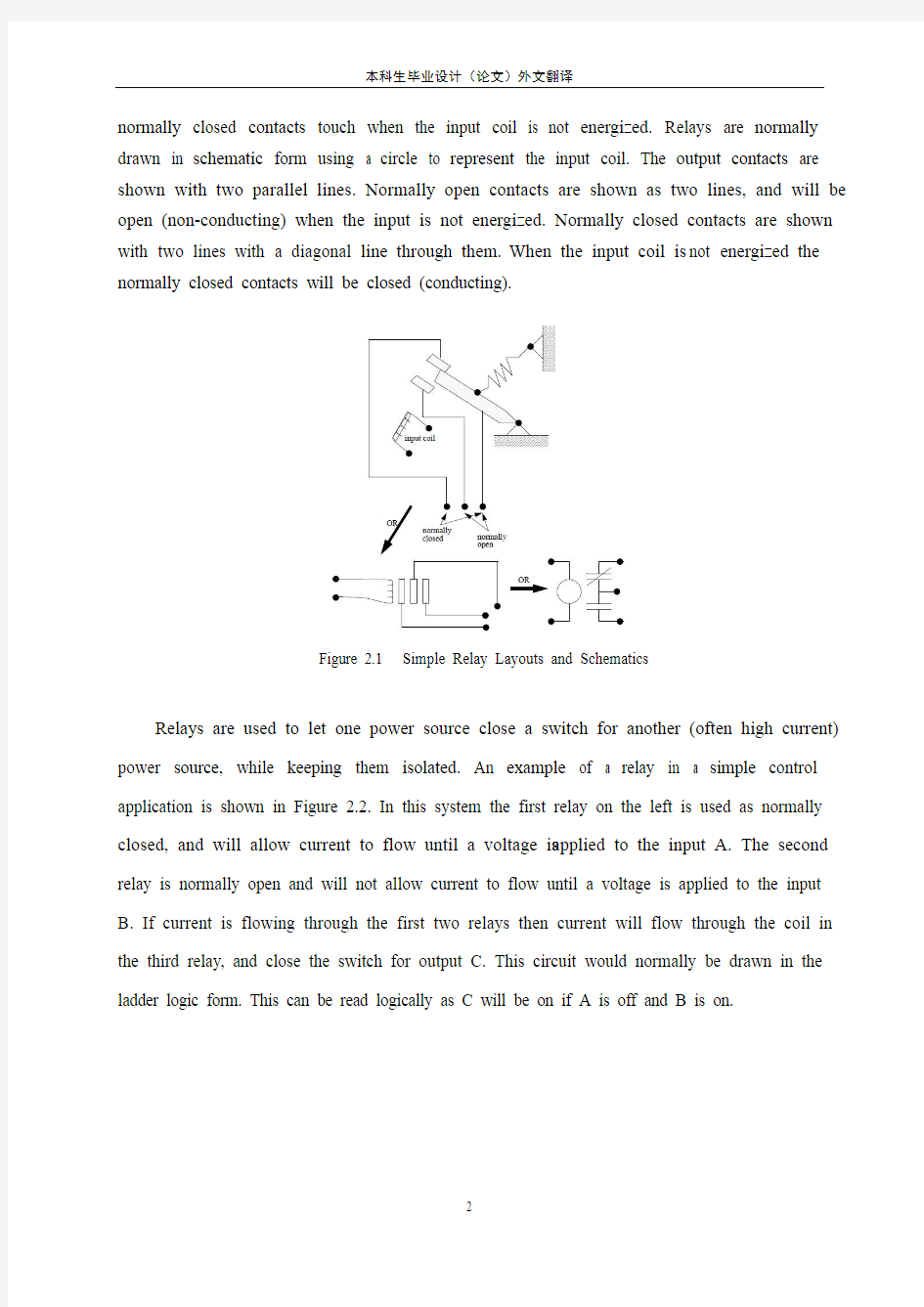
Modern control systems still include relays, but these are rarely used for logic. A relay is a simple device that uses a magnetic field to control a switch, as pictured in Figure 2.1. When a voltage is applied to the input coil, the resulting current creates a magnetic field. The magnetic field pulls a metal switch (or reed) towards it and the contacts touch, closing the switch. The contact that closes when the coil is energized is called normally open. The
normally closed contacts touch when the input coil is not energized. Relays are normally drawn in schematic form using a circle to represent the input coil. The output contacts are shown with two parallel lines. Normally open contacts are shown as two lines, and will be open (non-conducting) when the input is not energized. Normally closed contacts are shown with two lines with a diagonal line through them. When the input coil is not energized the normally closed contacts will be closed (conducting).
Figure 2.1 Simple Relay Layouts and Schematics
Relays are used to let one power source close a switch for another (often high current) power source, while keeping them isolated. An example of a relay in a simple control application is shown in Figure 2.2. In this system the first relay on the left is used as normally closed, and will allow current to flow until a voltage is applied to the input A. The second relay is normally open and will not allow current to flow until a voltage is applied to the input B. If current is flowing through the first two relays then current will flow through the coil in the third relay, and close the switch for output C. This circuit would normally be drawn in the ladder logic form. This can be read logically as C will be on if A is off and B is on.
Figure 2.2 A Simple Relay Controller
The example in Figure 2.2 does not show the entire control system, but only the logic. When we consider a PLC there are inputs, outputs, and the logic. Figure 2.3 shows a more complete representation of the PLC. Here there are two inputs from push buttons.We can imagine the inputs as activating 24V DC relay coils in the PLC. This in turn drives an output relay that switches 115V AC, that will turn on a light. Note, in actual PLCs inputs are never relays, but outputs are often relays. The ladder logic in the PLC is actually a computer program that the user can enter and change. Notice that both of the input push buttons are normally open, but the ladder logic inside the PLC has one normally open contact, and one normally closed contact. Do not think that the ladder logic in the PLC need so match the inputs or outputs. Many beginners will get caught trying to make the ladder logic match the
input types.
Figure 2.3 A PLC Illustrated With Relays
Many relays also have multiple outputs (throws) and this allows an output relay to also be an input simultaneously. The circuit shown in Figure 1.4 is an example of this, it is called a seal in circuit. In this circuit the current can flow through either branch of the circuit, through the contacts labelled A or B. The input B will only be on when the output B is on. If B is off, and A is energized, then B will turn on. If B turns on then the input B will turn on, and keep
output B on even if input A goes off. After B is turned on the output B will not turn off.
2.1.2 Programming
The first PLCs were programmed with a technique that was based on relay logic wiring schematics. This eliminated the need to teach the electricians, technicians and engineers how to program a computer - but, this method has stuck and it is the most common technique for programming PLCs today. An example of ladder logic can be seen in Figure 2.5. To interpret this diagram imagine that the power is on the vertical line on the left hand side, we call this the hot rail. On the right hand side is the neutral rail. In the figure there are two rungs, and on each rung there are combinations of inputs (two vertical lines) and outputs (circles). If the inputs are opened or closed in the right combination the power can flow from the hot rail, through the inputs, to power the outputs, and finally to the neutral rail. An input can come from a sensor, switch, or any other type of sensor. An output will be some device outside the PLC that is switched on or off, such as lights or motors. In the top rung the contacts are normally open and normally closed. Which means if input A is on and input B is off, then power will flow through the output and activate it. Any other combination of input values will result in the output X being off.
Figure 2.5 A Simple Ladder Logic Diagram
The second rung of Figure 2.5 is more complex, there are actually multiple combinations of inputs that will result in the output Y turning on. On the left most part of the rung, power could flow through the top if C is off and D is on. Power could also (and simultaneously) flow through the bottom if both E and F are true. This would get power half way across the rung, and then if G or H is true the power will be delivered to output Y. In later chapters we will examine how to interpret and construct these diagrams.
There are other methods for programming PLCs. One of the earliest techniques involved mnemonic instructions. These instructions can be derived directly from the ladder
logic diagrams and entered into the PLC through a simple programming terminal. An example of mnemonics is shown in Figure 2.6. In this example the instructions are read one line at a time from top to bottom. The first line 00000 has the instruction LDN (input load and not) for input A. . This will examine the input to the PLC and if it is off it will remember a 1 (or true), if it is on it will remember a 0 (or false). The next line uses an LD (input load) statement to look at the input. If the input is off it remembers a 0, if the input is on it remembers a 1 (note: this is the reverse of the LD). The AND statement recalls the last two numbers remembered and if the are both true the result is a 1, otherwise the result is a 0. This result now replaces the two numbers that were recalled, and there is only one number remembered. The process is repeated for lines 00003 and 00004, but when these are done there are now three numbers remembered. The oldest number is from the AND, the newer numbers are from the two LD instructions. The AND in line 00005 combines the results from the last LD instructions and now there are two numbers remembered. The OR instruction takes the two numbers now remaining and if either one is a 1 the result is a 1, otherwise the result is a 0. This result replaces the two numbers, and there is now a single number there. The last instruction is the ST (store output) that will look at the last value stored and if it is 1, the output will be turned on, if it is 0 the output will be turned off.
Figure 2.6 An Example of a Mnemonic Program and Equivalent Ladder Logic
The ladder logic program in Figure 2.6, is equivalent to the mnemonic program. Even if
you have programmed a PLC with ladder logic, it will be converted to mnemonic form before being used by the PLC. In the past mnemonic programming was the most common, but now it is uncommon for users to even see mnemonic programs.
Sequential Function Charts (SFCs) have been developed to accommodate the programming of more advanced systems. These are similar to flowcharts, but much more powerful. The example seen in Figure 2.7 is doing two different things. To read the chart, start at the top where is says start. Below this there is the double horizontal line that says follow both paths. As a result the PLC will start to follow the branch on the left and right hand sides separately and simultaneously. On the left there are two functions the first one is the power up function. This function will run until it decides it is done, and the power down function will come after. On the right hand side is the flash function, this will run until it is done. These functions look unexplained, but each function, such as power up will be a small ladder logic program. This method is much different from flowcharts because it does not have to follow a single path through the flowchart..
Figure 2.7 An Example of a Sequential Function Char
Structured Text programming has been developed as a more modern programming language. It is quite similar to languages such as BASIC. A simple example is shown in Figure 2.8. This example uses a PLC memory location i. This memory location is for an integer, as will be explained later in the book. The first line of the program sets the value to 0. The next line begins a loop, and will be where the loop returns to. The next line recalls the
value in location i, adds 1 to it and returns it to the same location. The next line checks to see if the loop should quit. If i is greater than or equal to 10, then the loop will quit, otherwise the computer will go back up to the REPEAT statement continue from there. Each time the program goes through this loop i will increase by 1 until the value reaches 10.
Figure 2.8 An Example of a Structured Text Program
2.1.3 PLC Connections
When a process is controlled by a PLC it uses inputs from sensors to make decisions and update outputs to drive actuators, as shown in Figure 2.9. The process is a real process that will change over time. Actuators will drive the system to new states (or modes of operation). This means that the controller is limited by the sensors available, if an input is not available, the controller will have no way to detect a condition.
Figure 2.9 The Separation of Controller and Process
The control loop is a continuous cycle of the PLC reading inputs, solving the ladder logic, and then changing the outputs. Like any computer this does not happen instantly. Figure 2.10 shows the basic operation cycle of a PLC. When power is turned on initially the PLC does a quick sanity check to ensure that the hardware is working properly.If there is a problem the PLC will halt and indicate there is an error. For example, if the PLC power is dropping and
about to go off this will result in one type of fault. If the PLC passes the sanity check it will then scan (read) all the inputs. After the inputs values are stored in memory the ladder logic will be scanned (solved) using the stored values not the current values. This is done to prevent logic problems when inputs change during the ladder logic scan. When the ladder logic scan is complete the outputs will be scanned (the output values will be changed). After this the system goes back to do a sanity check, and the loop continues indefinitely. Unlike normal computers, the entire program will be run every scan. Typical times for each of the stages is in the order of milliseconds.
Figure 2.10 The Scan Cycle of a PLC
2.1.4 Ladder Logic Inputs
PLC inputs are easily represented in ladder logic. In Figure 2.11 there are three types of inputs shown. The first two are normally open and normally closed inputs, discussed previously. The IIT (Immediate InpuT) function allows inputs to be read after the input scan, while the ladder logic is being scanned. This allows ladder logic to examine input values more often than once every cycle.
Figure 2.11 Ladder Logic Inputs
2.1.5 Ladder Logic Outputs
In ladder logic there are multiple types of outputs, but these are not consistently available on all PLCs. Some of the outputs will be externally connected to devices outside the PLC, but it is also possible to use internal memory locations in the PLC. Six types of outputs are shown in Figure 2.12. The first is a normal output, when energized the output will turn on, and energize an output. The circle with a diagonal line through is a normally on output. When energized the output will turn off. This type of output is not available on all PLC types. When initially energized the OSR (One Shot Relay) instruction will turn on for one scan, but then be off for all scans after, until it is turned off. The L (latch) and U (unlatch) instructions can be used to lock outputs on. When an L output is energized the output will turn on indefinitely, even when the output coil is deenergized. The output can only be turned off using a U output. The last instruction is the IOT (Immediate OutpuT) The last instruction is the IOT (Immediate OutpuT)that will allow outputs to be updated without having to wait for the ladder logic scan to be completed.
3.1 INPUTS AND OUTPUTS
Inputs to, and outputs from, a PLC are necessary to monitor and control a process. Both inputs and outputs can be categorized into two basic types: logical or continuous. Consider
the example of a light bulb. If it can only be turned on or off, it is logical control. If the light can be dimmed to different levels, it is continuous. Continuous values seem more intuitive, but logical values are preferred because they allow more certainty, and simplify control. As a result most controls applications (and PLCs) use logical inputs and outputs for most applications. Hence, we will discuss logical I/O and leave continuous I/O for later.
Outputs to actuators allow a PLC to cause something to happen in a process. A short list of popular actuators is given below in order of relative popularity.
Solenoid Valves - logical outputs that can switch a hydraulic or pneumatic flow. Lights - logical outputs that can often be powered directly from PLC output boards.
Motor Starters - motors often draw a large amount of current when started, so they require motor starters, which are basically large relays.
Servo Motors - a continuous output from the PLC can command a variable speed or position.
Outputs from PLCs are often relays, but they can also be solid state electronics such as transistors for DC outputs or Triacs for AC outputs. Continuous outputs require special output cards with digital to analog converters.
Inputs come from sensors that translate physical phenomena into electrical signals. Typical examples of sensors are listed below in relative order of popularity.
Proximity Switches - use inductance, capacitance or light to detect an object logically. Switches - mechanical mechanisms will open or close electrical contacts for a logical signal. Potentiometer - measures angular positions continuously, using resistance.
LVDT (linear variable differential transformer) - measures linear displacement continuously using magnetic coupling.
Inputs for a PLC come in a few basic varieties, the simplest are AC and DC inputs. Sourcing and sinking inputs are also popular. This output method dictates that a device does not supply any power. Instead, the device only switches current on or off, like a simple switch. Sinking - When active the output allows current to flow to a common ground. This is best selected when different voltages are supplied. Sourcing - When active, current flows from a
supply, through the output device and to ground. This method is best used when all devices use a single supply voltage. This is also referred to as NPN (sinking) and PNP (sourcing). PNP is more popular. This will be covered in detail in the chapter on sensors.
3.1.1 Inputs
In smaller PLCs the inputs are normally built in and are specified when purchasing the PLC. For larger PLCs the inputs are purchased as modules, or cards, with 8 or 16 inputs of the same type on each card. For discussion purposes we will discuss all inputs as if they have been purchased as cards. The list below shows typical ranges for input voltages, and is roughly in order of popularity. PLC input cards rarely supply power, this means that an external power supply is needed to supply power for the inputs and sensors. The example in Figure 3.1 shows how to connect an AC input card.
Figure 3.1 An AC Input Card and Ladder Logic
In the example there are two inputs, one is a normally open push button, and the second is a temperature switch, or thermal relay. (NOTE: These symbols are standard and will be discussed later in this chapter.) Both of the switches are powered by the positive/ hot output of
the 24Vac power supply - this is like the positive terminal on a DC supply. Power is supplied to the left side of both of the switches. When the switches are open there is no voltage passed to the input card. If either of the switches are closed power will be supplied to the input card. In this case inputs 1 and 3 are used - notice that the inputs start at 0. The input card compares these voltages to the common. If the input voltage is within a given tolerance range the inputs will switch on. Ladder logic is shown in the figure for the inputs. Here it uses Allen Bradley notation for PLC-5 racks. At the top is the location of the input card I:013 which indicates that the card is an Input card in rack 01 in slot 3. The input number on the card is shown below the contact as 01 and 03.
Many beginners become confused about where connections are needed in the circuit above. The key word to remember is circuit, which means that there is a full loop that the voltage must be able to follow. In Figure 3.1 we can start following the circuit (loop) at the power supply. The path goes through the switches, through the input card, and back to the power supply where it flows back through to the start. In a full PLC implementation there will be many circuits that must each be complete. A second important concept is the common. Here the neutral on the power supply is the common, or reference voltage. In effect we have chosen this to be our 0V reference, and all other voltages are measured relative to it. If we had a second power supply, we would also need to connect the neutral so that both neutrals would be connected to the same common. Often common and ground will be confused. The common is a reference, or datum voltage that is used for 0V, but the ground is used to prevent shocks and damage to equipment. The ground is connected under a building to a metal pipe or grid in the ground. This is connected to the electrical system of a building, to the power outlets, where the metal cases of electrical equipment are connected. When power flows through the ground it is bad. Unfortunately many engineers, and manufacturers mix up ground and common. It is very common to find a power supply with the ground and common mislabeled.
One final concept that tends to trap beginners is that each input card is isolated. This means that if you have connected a common to only one card, then the other cards are not connected. When this happens the other cards will not work properly. You must connect a
common for each of the output cards.
3.1.2.Output Modules
As with input modules, output modules rarely supply any power, but instead act as switches. External power supplies are connected to the output card and the card will switch the power on or off for each output. Typical output voltages are listed below, and roughly ordered by popularity.
120 Vac
24 Vdc
12-48 Vac
12-48 Vdc
5Vdc (TTL)
230 Vac
These cards typically have 8 to 16 outputs of the same type and can be purchased with different current ratings. A common choice when purchasing output cards is relays, transistors or triacs. Relays are the most flexible output devices. They are capable of switching both AC and DC outputs. But, they are slower (about 10ms switching is typical), they are bulkier, they cost more, and they will wear out after millions of cycles. Relay outputs are often called dry contacts. Transistors are limited to DC outputs, and Triacs are limited to AC outputs. Transistor and triac outputs are called switched outputs. Dry contacts - a separate relay is dedicated to each output.
This allows mixed voltages (AC or DC and voltage levels up to the maximum), as well as isolated outputs to protect other outputs and the PLC. Response times are often greater than 10ms. This method is the least sensitive to voltage variations and spikes. Switched outputs - a voltage is supplied to the PLC card, and the card switches it to different outputs using solid state circuitry (transistors, triacs, etc.) Triacs are well suited to AC devices requiring less than 1A. Transistor outputs use NPN or PNP transistors up to 1A typically. Their response time is well under 1ms.
中文翻译
自动化制造系统与PLC
2.1介绍
控制工程随着时间的推移在不断发展。过去的人们主要致力于控制系统方面的研究。而最近电力已被应用于控制,早期电气控制是基于继电器的。这些继电器使其可以在没有机械开关的情况下被开启和关闭。使用继电器进行简单逻辑控制的方法很普遍。低成本计算机的发展带来了新一次的革命,可编程逻辑控制器(PLC)出现于十九世纪70年代,如今它已成为制造控制的最普遍选择。
PLC已逐渐在工厂车间中得到普及并很可能在未来的一段时间内占据主导地位。这一切都缘于PLC这些的优点:
1.能高效地控制复杂系统
2.应用灵活并能简单迅速地循环控制其他系统
3.强大的计算能力使其可以控制极其复杂的系统
4.故障排除帮助使编程更加容易,并可减少停机时间
5.可靠地组件使其有更长的使用寿命
2.1.1梯形逻辑
梯形逻辑是用于PLC的主要编程方法。正如之前所说,梯形逻辑已被用来模仿继电器逻辑。使用继电器逻辑图进行编程的决定是一个战略决策。通过选择梯形逻辑作为主要的编程方法,使培训工程师和商人所需要的资金极大的减少。
现代控制系统仍然包括继电器,但它很少用于逻辑。继电器是一个使用磁场来控制开关的简单设备,如图2.1。当电压作用于输入线圈产生磁场,磁场吸引金属开关使触点接触,则开关闭合。通电时闭合的触点称为常开触点,不通电时闭合的触点称为常闭触点。继电器通常在示意图中使用一个圆圈代表输入线圈,输出触点用两个平行线表示。常开触点用两根线表示并在输入端不通电时是开启(不导电)的,常闭触点用两根线和
一个对角线穿过它们来表示,当输入线圈不通电时,常闭触点是闭合(导电)的。
输入线圈
或
常闭开关常开开关
或
图2.1 简单的布局和继电器电路图
继电器用于是让一个电源控制关闭另一(通常是高电流)电源的开关,同时保持它们之间隔离。举一个用于简单控制的继电器的例子,如图2.2所示。在这个系统中,左边第一个继电器被用作常闭触点,并允许电流流过,直到输入端通电才断开。第二个继电器被用作常开触点,不允许电流通过,直到电压作用于输入端B。如果电流流过前两个继电器并通过继电器3中的线圈并闭合输出端C的开关。此电路通常被化成梯形图形式。这可以理解为如果A断开B闭合则C接通。
继电器逻辑
输入A(常闭)输入B(常开)输入C(常开)
梯形逻辑
图2.2一个简单的继电器控制器
图2.2中的例子没有显示整个控制系统,只有逻辑。当我们考虑一个PLC有输入,输出,和逻辑时,图1.3显示的更全面。这里有一组双输入按钮,我们可以想像将输入端接在24V直流电源上,用来驱动器是输出继电器的115V交流电开关,结果点亮了一盏灯。请注意,在实际情况下PLC的输入端从来不接继电器,而是在输出端。PLC梯形逻辑其实就是一种用户可以进入和更改的电脑程序。注意到两个输入的按钮都是常开的,但PLC梯形图逻辑有一个常开触点,和一个常闭触点。在PLC梯形逻辑图不需要匹配输入或输出。许多初学者会试图使梯形逻辑与它的输入端类型相匹配。
图2.3一个PLC 的继电器说明
许多继电器也有多个输出(输入),这允许输出继电器可以同时输入。图2.4所示的电路就是一个例子,它是在电路里称为保持电路。此电路的电流可流过两个电路分支中的任何一个,通过接触开关A 或B ,只有输出端B 继电器通电,触点B 才会闭合。如果B 是断开的,而使A 通电,那么B 将闭合。如果输出端B 继电器一直通电,即使A 触点断开B 触点也将一直保持闭合。当B 触点闭合后,继电器B 将一直通电。
图2.4一个保持电路
输出
输入
梯形逻辑
电源
按钮
交流电源
灯泡
2.1.2编程
最初的PLC 是基于继电器逻辑接线图技术进行编程。除了对教电工,技术员和工程师电脑编程的需求外,这种方法还是一直是被认可的,而且它现在已成为最普遍的的PLC 的编程技术。图2.5是一个简单梯形逻辑的例子。解释一下这个梯形图,假象左侧的垂直线为电源,我们称之为热线。而最右断端的垂线称之为零线。中间有两个梯级,每个梯级有一组输入(2短垂直线)和一个输出(圆圈)。如果输入端以一个正确的组合断开或闭合,电流将从热线流出通过输入端,作用于输出端,最后到达零线。输入可来自于一个传感器,开关,或任何其他类型的传感器。输出端是PLC 外一些被控制开关的设备,如灯泡或电机之类。在上面这个梯级,有一个动合触点和动断触点,即如果A 通电B 断电则电流将流过输出端X 并驱动它工作,其他形式的组合将导致输出端X 断开。
图2.5一个简单的梯形逻辑图
图2.5的第二个梯级更复杂,实际上输入端有多种开闭组合可使输出端Y 工作。在梯级的左侧,如果C 断电D 通电,则有电流流过,而如果E,F 通电,电流也可以从下面支路流过,只是这个梯级导通的一半条件,后面的G 或H 如果通电,电流将通过其中一个流向输出端Y ,在后面的章节我们将讲解如何设计和绘制梯形图。
还有一些其他的PLC 编程方法。其中最早的一个技术涉及助记符指令。这些指令可直接由梯形逻辑图生成,并通过简单的编程终端输入到PLC 中。图2.6是一个助记符指令的例子。在这个例子中,一次一行地从上到下读取指令。第一行00000有对输入端0001的指令LDN (是否输入加载),这将检查PLC 的输入端,如果是断点状态将被记为1(或
注意:电源电流需要输入端(A,B,C,D,E,F,G ,H )的某些组合才能打开输
出端(X,Y ) 零线
火线 输入端 输出端
真),如果处于通电状态将被记为0(或假)。下一行使用一个LD(输入加载)语句查看输入。如果输入端是断电状态记为0,通电记为1(注意:这是相反的)。AND指令调用之前存储的最后两位数,如果都是真则结果为1,否则结果为0。这一结果取代了那两个被调用的数,只有一个数字被寄存。这个过程在00003和00004行中重复,当执行完毕后有三个数被寄存。第一个数来自AND指令,后两个数来自两个LD指令。0005行中的AND指令与前面的LD指令结果结合,使现在只有两个数字被存储。OR指令采用现在剩下的两个数字,任意一个是1则结果是1,否则结果是0。这一结果覆盖了前面两个数,而现在有一个数。最后一个指令是ST(存储输出),将看最后一个数进行存储,如果是1,输出将通电,如果是0输出将断开。
助记码与下面的梯形逻辑等同
图2.6一个助记符编程和对应的梯形逻辑实例
图2.6梯形逻辑程序,相当于助记符程序。即使你已为PLC梯形编好程,在PLC使用前它还是将转化为助记符形式。在过去助记符编程是最普遍的,但现在这种方法不常用了,甚至连助记符程序都很少见。
顺序功能图(SFCs)编程已经发展成为适用于更先进系统的编程方式。它类似于流
Injection Molding The basic concept of injection molding revolves around the ability of a thermoplastic material to be softened by heat and to harden when cooled .In most operations ,granular material (the plastic resin) is fed into one end of the cylinder (usually through a feeding device known as a hopper ),heated, and softened(plasticized or plasticized),forced out the other end of the cylinder, while it is still in the form of a melt, through a nozzle into a relatively cool mold held closed under pressure.Here,the melt cools and hardens until fully set-up. The mold is then opened, the piece ejected, and the sequence repeated. Thus, the significant elements of an injection molding machine become: 1) the way in which the melt is plasticized (softened) and forced into the mold (called the injection unit); 2) the system for opening the mold and closing it under pressure (called the clamping unit);3) the type of mold used;4) the machine controls. The part of an injection-molding machine, which converts a plastic material from a sold phase to homogeneous seni-liguid phase by raising its temperature .This unit maintains the material at a present temperature and force it through the injection unit nozzle into a mold .The plunger is a combination of the injection and plasticizing device in which a heating chamber is mounted between the plunger and mold. This chamber heats the plastic material by conduction .The plunger, on each stroke; pushes unbelted plastic material into the chamber, which in turn forces plastic melt at the front of the chamber out through the nozzle The part of an injection molding machine in which the mold is mounted, and which provides the motion and force to open and close the mold and to hold the mold close with force during injection .This unit can also provide other features necessary for the effective functioning of the molding operation .Moving
附录一英文科技文献翻译 英文原文: Experimental investigation of laser surface textured parallel thrust bearings Performance enhancements by laser surface texturing (LST) of parallel-thrust bearings is experimentally investigated. Test results are compared with a theoretical model and good correlation is found over the relevant operating conditions. A compari- son of the performance of unidirectional and bi-directional partial-LST bearings with that of a baseline, untextured bearing is presented showing the bene?ts of LST in terms of increased clearance and reduced friction. KEY WORDS: ?uid ?lm bearings, slider bearings, surface texturing 1. Introduction The classical theory of hydrodynamic lubrication yields linear (Couette) velocity distribution with zero pressure gradients between smooth parallel surfaces under steady-state sliding. This results in an unstable hydrodynamic ?lm that would collapse under any external force acting normal to the surfaces. However, experience shows that stable lubricating ?lms can develop between parallel sliding surfaces, generally because of some mechanism that relaxes one or more of the assumptions of the classical theory. A stable ?uid ?lm with su?cient load-carrying capacity in parallel sliding surfaces can be obtained, for example, with macro or micro surface structure of di?erent types. These include waviness [1] and protruding microasperities [2–4]. A good literature review on the subject can be found in Ref. [5]. More recently, laser surface texturing (LST) [6–8], as well as inlet roughening by longitudinal or transverse grooves [9] were suggested to provide load capacity in parallel sliding. The inlet roughness concept of Tonder [9] is based on ??e?ective clearance‘‘ reduction in the sliding direction and in this respect it is identical to the par- tial-LST concept described in ref. [10] for generating hydrostatic e?ect in high-pressure mechanical seals. Very recently Wang et al. [11] demonstrated experimentally a doubling of the load-carrying capacity for the surface- texture design by reactive ion etching of SiC
外文出处: 《Exploiting Software How to Break Code》By Greg Hoglund, Gary McGraw Publisher : Addison Wesley Pub Date : February 17, 2004 ISBN : 0-201-78695-8 译文标题: JDBC接口技术 译文: JDBC是一种可用于执行SQL语句的JavaAPI(ApplicationProgrammingInterface应用程序设计接口)。它由一些Java语言编写的类和界面组成。JDBC为数据库应用开发人员、数据库前台工具开发人员提供了一种标准的应用程序设计接口,使开发人员可以用纯Java语言编写完整的数据库应用程序。 一、ODBC到JDBC的发展历程 说到JDBC,很容易让人联想到另一个十分熟悉的字眼“ODBC”。它们之间有没有联系呢?如果有,那么它们之间又是怎样的关系呢? ODBC是OpenDatabaseConnectivity的英文简写。它是一种用来在相关或不相关的数据库管理系统(DBMS)中存取数据的,用C语言实现的,标准应用程序数据接口。通过ODBCAPI,应用程序可以存取保存在多种不同数据库管理系统(DBMS)中的数据,而不论每个DBMS使用了何种数据存储格式和编程接口。 1.ODBC的结构模型 ODBC的结构包括四个主要部分:应用程序接口、驱动器管理器、数据库驱动器和数据源。应用程序接口:屏蔽不同的ODBC数据库驱动器之间函数调用的差别,为用户提供统一的SQL编程接口。 驱动器管理器:为应用程序装载数据库驱动器。 数据库驱动器:实现ODBC的函数调用,提供对特定数据源的SQL请求。如果需要,数据库驱动器将修改应用程序的请求,使得请求符合相关的DBMS所支持的文法。 数据源:由用户想要存取的数据以及与它相关的操作系统、DBMS和用于访问DBMS的网络平台组成。 虽然ODBC驱动器管理器的主要目的是加载数据库驱动器,以便ODBC函数调用,但是数据库驱动器本身也执行ODBC函数调用,并与数据库相互配合。因此当应用系统发出调用与数据源进行连接时,数据库驱动器能管理通信协议。当建立起与数据源的连接时,数据库驱动器便能处理应用系统向DBMS发出的请求,对分析或发自数据源的设计进行必要的翻译,并将结果返回给应用系统。 2.JDBC的诞生 自从Java语言于1995年5月正式公布以来,Java风靡全球。出现大量的用java语言编写的程序,其中也包括数据库应用程序。由于没有一个Java语言的API,编程人员不得不在Java程序中加入C语言的ODBC函数调用。这就使很多Java的优秀特性无法充分发挥,比如平台无关性、面向对象特性等。随着越来越多的编程人员对Java语言的日益喜爱,越来越多的公司在Java程序开发上投入的精力日益增加,对java语言接口的访问数据库的API 的要求越来越强烈。也由于ODBC的有其不足之处,比如它并不容易使用,没有面向对象的特性等等,SUN公司决定开发一Java语言为接口的数据库应用程序开发接口。在JDK1.x 版本中,JDBC只是一个可选部件,到了JDK1.1公布时,SQL类包(也就是JDBCAPI)
控制系统基础论文中英文资料外文翻译文献 文献翻译 原文: Numerical Control One of the most fundamental concepts in the area of advanced manufacturing technologies is numerical control (NC).Prior to the advent of NC, all machine tools were manual operated and controlled. Among the many limitations associated with manual control machine tools, perhaps none is more prominent than the limitation of operator skills. With manual control, the quality of the product is directly related to and limited to the skills of the operator . Numerical control represents the first major step away from human control of machine tools. Numerical control means the control of machine tools and other manufacturing systems though the use of prerecorded, written symbolic instructions. Rather than operating a machine tool, an NC technician writes a program that issues operational instructions to the machine tool, For a machine tool to be numerically controlled , it must be interfaced with a device for accepting and decoding the p2ogrammed instructions, known as a reader. Numerical control was developed to overcome the limitation of human operator , and it has done so . Numerical control machines are more accurate than manually operated machines , they can produce parts more uniformly , they are faster, and the long-run tooling costs are lower . The development of NC led to the development of several other innovations in manufacturing technology: 1.Electrical discharge machining. https://www.doczj.com/doc/c39514412.html,ser cutting. 3.Electron beam welding.
附录1:外文资料翻译 A1.1外文资料题目 26.22 接地故障电路开关 我们目前为止报道的接地方法通常是充分的, 但更加进一步的安全措施在某些情况下是必要的。假设例如, 有人将他的手指伸进灯口(如Fig.26.45示)。虽然金属封入物安全地接地, 但那人仍将受到痛苦的震动。或假设1个120V 的电炉掉入游泳池。发热设备和联络装置将导致电流流入在水池中的危害,即使电路的外壳被安全地接地,现在已经发展为当这样的事件发生时,设备的电源将被切断。如果接地电流超过5mA ,接地开关将在5 ms 内跳掉,这些装置怎么运行的? 如Fig.26.46所示,一台小变流器缠绕上导线 ,第二步是要连接到可能触发开合120 V 线的一台敏感电子探测器。 在正常情况下流过导体的电流W I 与中性点上的电流N I 准切的相等,因此流经核心的净潮流(N W I I -)是零。 结果,在核心没有产生电流,导致的电压F E 为零,并且开关CB 没有动作。 假设如果某人接触了一个终端(图Fig.26.45示),故障电流F I 将直接地从载电线漏到地面,这是可能发生的。如果绝缘材料在马达和它的地面封入物之间断开,故障电流也会被产生。在以下任何情况下,流经CT 的孔的净潮流等于F I 或L I ,不再是零。电流被产生,并且产生了可以控制CB 开关的电压F E 。 由于5 mA 不平衡状态只必须被检测出,变压器的核心一定是非常有渗透性的在低通量密度。 Supermalloy 是最为常用的,因为它有相对渗透性典型地70000在通量密度仅4mT 。 26.23 t I 2是导体迅速发热的因素 它有时发生于导体短期内电流远大于正常值的情况下,R I 2损失非常大并且导体的温度可以在数秒内上升几百度。例如,当发生严重短路时,在保险丝或开关作用之前,会有很大的电流流过导体和电缆。 此外,热量没有时间被消散到周围,因此导体的温度非常迅速地增加。 在这些情况下什么是温度上升? 假设导体有大量m ,电阻R 和热量热容量c 。 而且,假设电流是I ,并且那它流动在t 少于15秒期间。 在导体上引起的热 Rt I Q 2= 从Eq.3.17,在功率一定的情况下我们可以计算导体上升的温度差:
(此文档为word格式,下载后您可任意编辑修改!) 冷冲模具使用寿命的影响及对策 冲压模具概述 冲压模具--在冷冲压加工中,将材料(金属或非金属)加工成零件(或半成品)的一种特殊工艺装备,称为冷冲压模具(俗称冷冲模)。冲压--是在室温下,利用安装在压力机上的模具对材料施加压力,使其产生分离或塑性变形,从而获得所需零件的一种压力加工方法。 冲压模具的形式很多,一般可按以下几个主要特征分类: 1?根据工艺性质分类 (1)冲裁模沿封闭或敞开的轮廓线使材料产生分离的模具。如落料模、冲孔模、切断模、切口模、切边模、剖切模等。 (2)弯曲模使板料毛坯或其他坯料沿着直线(弯曲线)产生弯曲变形,从而获得一定角度和形状的工件的模具。 (3)拉深模是把板料毛坯制成开口空心件,或使空心件进一步改变形状和尺寸的模具。 (4)成形模是将毛坯或半成品工件按图凸、凹模的形状直接复制成形,而材料本身仅产生局部塑性变形的模具。如胀形模、缩口模、扩口模、起伏成形模、翻边模、整形模等。2?根据工序组合程度分类 (1)单工序模在压力机的一次行程中,只完成一道冲压工序的模具。 (2)复合模只有一个工位,在压力机的一次行程中,在同一工位上同时完成两道或两道以上冲压工序的模具。 (3)级进模(也称连续模) 在毛坯的送进方向上,具有两个或更多的工位,在压力机的一次行程中,在不同的工位上逐次完成两道或两道以上冲压工序的模具。 冲冷冲模全称为冷冲压模具。 冷冲压模具是一种应用于模具行业冷冲压模具及其配件所需高性能结构陶瓷材料的制备方法,高性能陶瓷模具及其配件材料由氧化锆、氧化钇粉中加铝、错元素构成,制备工艺是将氧化锆溶液、氧化钇溶液、氧化错溶液、氧化铝溶液按一定比例混合配成母液,滴入碳酸氢铵,采用共沉淀方法合成模具及其配件陶瓷材料所需的原材料,反应生成的沉淀经滤水、干燥,煅烧得到高性能陶瓷模具及其配件材料超微粉,再经过成型、烧结、精加工,便得到高性能陶瓷模具及其配件材料。本发明的优点是本发明制成的冷冲压模具及其配件使用寿命长,在冲压过程中未出现模具及其配件与冲压件产生粘结现象,冲压件表面光滑、无毛刺,完全可以替代传统高速钢、钨钢材料。 冷冲模具主要零件冷冲模具是冲压加工的主要工艺装备,冲压制件就是靠上、下模具的相对运动来完成的。 加工时由于上、下模具之间不断地分合,如果操作工人的手指不断进入或停留在模具闭合区,便会对其人身安全带来严重威胁。 1
本科毕业论文(设计) 外文翻译 学院:机电工程学院 专业:机械工程及自动化 姓名:高峰 指导教师:李延胜 2011年05 月10日 教育部办公厅 Failure Analysis,Dimensional Determination And
Analysis,Applications Of Cams INTRODUCTION It is absolutely essential that a design engineer know how and why parts fail so that reliable machines that require minimum maintenance can be designed.Sometimes a failure can be serious,such as when a tire blows out on an automobile traveling at high speed.On the other hand,a failure may be no more than a nuisance.An example is the loosening of the radiator hose in an automobile cooling system.The consequence of this latter failure is usually the loss of some radiator coolant,a condition that is readily detected and corrected.The type of load a part absorbs is just as significant as the magnitude.Generally speaking,dynamic loads with direction reversals cause greater difficulty than static loads,and therefore,fatigue strength must be considered.Another concern is whether the material is ductile or brittle.For example,brittle materials are considered to be unacceptable where fatigue is involved. Many people mistakingly interpret the word failure to mean the actual breakage of a part.However,a design engineer must consider a broader understanding of what appreciable deformation occurs.A ductile material,however will deform a large amount prior to rupture.Excessive deformation,without fracture,may cause a machine to fail because the deformed part interferes with a moving second part.Therefore,a part fails(even if it has not physically broken)whenever it no longer fulfills its required function.Sometimes failure may be due to abnormal friction or vibration between two mating parts.Failure also may be due to a phenomenon called creep,which is the plastic flow of a material under load at elevated temperatures.In addition,the actual shape of a part may be responsible for failure.For example,stress concentrations due to sudden changes in contour must be taken into account.Evaluation of stress considerations is especially important when there are dynamic loads with direction reversals and the material is not very ductile. In general,the design engineer must consider all possible modes of failure,which include the following. ——Stress ——Deformation ——Wear ——Corrosion ——Vibration ——Environmental damage ——Loosening of fastening devices
外文翻译 专业机械设计制造及其自动化学生姓名刘链柱 班级机制111 学号1110101102 指导教师葛友华
外文资料名称: Design and performance evaluation of vacuum cleaners using cyclone technology 外文资料出处:Korean J. Chem. Eng., 23(6), (用外文写) 925-930 (2006) 附件: 1.外文资料翻译译文 2.外文原文
应用旋风技术真空吸尘器的设计和性能介绍 吉尔泰金,洪城铱昌,宰瑾李, 刘链柱译 摘要:旋风型分离器技术用于真空吸尘器 - 轴向进流旋风和切向进气道流旋风有效地收集粉尘和降低压力降已被实验研究。优化设计等因素作为集尘效率,压降,并切成尺寸被粒度对应于分级收集的50%的效率进行了研究。颗粒切成大小降低入口面积,体直径,减小涡取景器直径的旋风。切向入口的双流量气旋具有良好的性能考虑的350毫米汞柱的低压降和为1.5μm的质量中位直径在1米3的流量的截止尺寸。一使用切向入口的双流量旋风吸尘器示出了势是一种有效的方法,用于收集在家庭中产生的粉尘。 摘要及关键词:吸尘器; 粉尘; 旋风分离器 引言 我们这个时代的很大一部分都花在了房子,工作场所,或其他建筑,因此,室内空间应该是既舒适情绪和卫生。但室内空气中含有超过室外空气因气密性的二次污染物,毒物,食品气味。这是通过使用产生在建筑中的新材料和设备。真空吸尘器为代表的家电去除有害物质从地板到地毯所用的商用真空吸尘器房子由纸过滤,预过滤器和排气过滤器通过洁净的空气排放到大气中。虽然真空吸尘器是方便在使用中,吸入压力下降说唱空转成比例地清洗的时间,以及纸过滤器也应定期更换,由于压力下降,气味和细菌通过纸过滤器内的残留粉尘。 图1示出了大气气溶胶的粒度分布通常是双峰形,在粗颗粒(>2.0微米)模式为主要的外部来源,如风吹尘,海盐喷雾,火山,从工厂直接排放和车辆废气排放,以及那些在细颗粒模式包括燃烧或光化学反应。表1显示模式,典型的大气航空的直径和质量浓度溶胶被许多研究者测量。精细模式在0.18?0.36 在5.7到25微米尺寸范围微米尺寸范围。质量浓度为2?205微克,可直接在大气气溶胶和 3.85至36.3μg/m3柴油气溶胶。
毕业设计(论文)外文资料翻译 学院:机械工程学院 专业:机械设计制造及其自动化 姓名: 学号:XXXXXXXXXX 外文出处:《Computational Intelligence and (用外文写)Design》 附件: 1.外文资料翻译译文;2.外文原文。 注:请将该封面与附件装订成册。
附件1:外文资料翻译译文 基于微型计算机的步进电机控制系统设计 孟天星余兰兰 山东理工大学电子与电气工程学院 山东省淄博市 摘要 本文详细地介绍了一种以AT89C51为核心的步进电机控制系统。该系统设计包括硬件设计、软件设计和电路设计。电路设计模块包括键盘输入模块、LED显示模块、发光二极管状态显示和报警模块。按键可以输入设定步进电机的启停、转速、转向,改变转速、转向等的状态参数。通过键盘输入的状态参数来控制步进电机的步进位置和步进速度进而驱动负载执行预订的工作。运用显示电路来显示步进电机的输入数据和运行状态。AT89C51单片机通过指令系统和编译程序来执行软件部分。通过反馈检测模块,该系统可以很好地完成上述功能。 关键词:步进电机,AT89C51单片机,驱动器,速度控制 1概述 步进电机因为具有较高的精度而被广泛地应用于运动控制系统,例如机器人、打印机、软盘驱动机、绘图仪、机械式阀体等等。过去传统的步进电机控制电路和驱动电路设计方法通常都极为复杂,由成本很高而且实用性很差的电器元件组成。结合微型计算机技术和软件编程技术的设计方法成功地避免了设计大量复杂的电路,降低了使用元件的成本,使步进电机的应用更广泛更灵活。本文步进电机控制系统是基于AT89C51单片机进行设计的,它具有电路简单、结构紧凑的特点,能进行加减速,转向和角度控制。它仅仅需要修改控制程序就可以对各种不同型号的步进电机进行控制而不需要改变硬件电路,所以它具有很广泛的应用领域。 2设计方案 该系统以AT89C51单片机为核心来控制步进电机。电路设计包括键盘输入电路、LED显示电路、发光二极管显示电路和报警电路,系统原理框图如图1所示。 At89c51单片机的P2口输出控制步进电机速度的时钟脉冲信号和控制步进电机运转方向的高低电平。通过定时程序和延时程序可以控制步进电机的速度和在某一
中文翻译 STC89C52处理芯片 电气工程的研究和解决方案中心(ceers) 艾哈迈德为吉.波特 首要性能: 与MCS-51单片机产物兼容、8K字节在系统可编程视频存储器、1000次擦拭周期,全静态操作:0Hz~33Hz、三级加密程序存储器,32个可编程I/O接口线、三个16位定时器(计数器),八个中断源、低功能耗空闲和掉电模式、掉电后间断可唤醒,看门狗定时器、双数值指针,掉电标示符。 关键词:单片机,UART串行通道,掉电标示符等 前言 可以说,二十世纪跨越了三个“点”的时代,即电气时代,电子时代和现已进入的电脑时代。不过,这种电脑,通常指的是个人计算机,简称PC机。还有就是把智能赋予各种机械的单片机(亦称微控制器)。顾名思义,这种计算机的最小系统只用了一片集成电路,即可进行简单的运算可控制。因为它体积小,通常都是藏在被控机械的内部里面。它在整个装置中,起着有如人类头脑的作用,他出了毛病,整个装置就会瘫痪。现在,单片机的种类和适用领域已经十分广泛,如智能仪表、实施工控、通讯设备、导航系统、家用电器等。各种产品一旦用上了单片机,就你能起到产品升级换代的功效,常在产品名称前冠以形容词——“智能型”,如智能洗衣机等。接下来就是关于国产STC89C52单片机的一些基本参数。 功能特性描述: STC89C52单片机是一种低功耗、高性能CMOS8位微控制器,具有8K在系统可编程视频播放存贮器使用高密度非易失性存储器技术制造,与工业80C51 产物指令和引脚完全兼容。片上反射速度允许程序存储器在系统可编程,也适用于常规的程序编写器。在其单芯片上,拥有灵敏小巧的八位中央处理器和在线系统可编程反射,这些使用上STC89C52微控制器为众多嵌入式的控制应用系统提供高度矫捷的、更加有用的解决方案。STC89C52微控制器具有以下的标准功效:8K字节的反射速度,256字节的随机存取储存器,32位I/O串口线,看门狗定时器,2个数值指针,三个16 为定时器、计数器,一个6向量2级间断结构,片内晶振及钟表电路。另外,STC89C52可降至0HZ静态逻辑操作,支持两种软件可选择节电模式、间断继续工作。空闲模式下,CPU停止工作,允许RAM、定时器/计数器、串口、间断继续工作。掉电保护体式格局下,RAM内容被生成,振动器被冻结,单片机一切的工作停止,直到下一个间断或者硬件复位为止。8位微型控制器8K字节在系统中可编程FlashSTC89C52.。
济南大学泉城学院 毕业设计外文资料翻译 题目现代快速经济制造模具技术 专业机械制造及其自动化 班级专升本1302班 学生刘计良 学号2013040156 指导教师刘彦 二〇一五年三月十六日
Int J Adv Manuf Technol ,(2011) 53:1–10DOI 10.1007/s00170-010-2796-y Modular design applied to beverage-container injection molds Ming-Shyan Huang & Ming-Kai Hsu Received: 16 March 2010 / Accepted: 15 June 2010 / Published online: 25 June 2010 # Springer-Verlag London Limited 2010 Modular design applied to beverage-container injection molds The Abstract: This work applies modular design concepts to designating beverage-container injection molds. This study aims to develop a method of controlling costs and time in relation to mold development, and also to improve product design. This investigation comprises two parts: functional-ity coding, and establishing a standard operation procedure, specifically designed for beverage-container injection mold design and manufacturing. First, the injection mold is divided into several modules, each with a specific function. Each module is further divided into several structural units possessing sub-function or sub-sub-function. Next, dimen-sions and specifications of each unit are standardized and a compatible interface is constructed linking relevant units. This work employs a cup-shaped beverage container to experimentally assess the performance of the modular design approach. The experimental results indicate that the modular design approach to manufacturing injection molds shortens development time by 36% and reduces costs by 19 23% compared with the conventional ap-proach. Meanwhile, the information on
沈阳工业大学工程学院 毕业设计(论文)外文翻译 毕业设计(论文)题目:工具盒盖注塑模具设计 外文题目:Friction , Lubrication of Bearing 译文题目:轴承的摩擦与润滑 系(部):机械系 专业班级:机械设计制造及其自动化0801 学生姓名:王宝帅 指导教师:魏晓波 2010年10 月15 日
外文文献原文: Friction , Lubrication of Bearing In many of the problem thus far , the student has been asked to disregard or neglect friction . Actually , friction is present to some degree whenever two parts are in contact and move on each other. The term friction refers to the resistance of two or more parts to movement. Friction is harmful or valuable depending upon where it occurs. friction is necessary for fastening devices such as screws and rivets which depend upon friction to hold the fastener and the parts together. Belt drivers, brakes, and tires are additional applications where friction is necessary. The friction of moving parts in a machine is harmful because it reduces the mechanical advantage of the device. The heat produced by friction is lost energy because no work takes place. Also , greater power is required to overcome the increased friction. Heat is destructive in that it causes expansion. Expansion may cause a bearing or sliding surface to fit tighter. If a great enough pressure builds up because made from low temperature materials may melt. There are three types of friction which must be overcome in moving parts: (1)starting, (2)sliding, and(3)rolling. Starting friction is the friction between two solids that tend to resist movement. When two parts are at a state of rest, the surface irregularities of both parts tend to interlock and form a wedging action. To produce motion in these parts, the wedge-shaped peaks and valleys of the stationary surfaces must be made to slide out and over each other. The rougher the two surfaces, the greater is starting friction resulting from their movement . Since there is usually no fixed pattern between the peaks and valleys of two mating parts, the irregularities do not interlock once the parts are in motion but slide over each other. The friction of the two surfaces is known as sliding friction. As shown in figure ,starting friction is always greater than sliding friction . Rolling friction occurs when roller devces are subjected to tremendous stress which cause the parts to change shape or deform. Under these conditions, the material in front of a roller tends to pile up and forces the object to roll slightly uphill. This changing of shape , known as deformation, causes a movement of molecules. As a result ,heat is produced from the added energy required to keep the parts turning and overcome friction. The friction caused by the wedging action of surface irregularities can be overcome