6 B 20 EN ? 6/2011
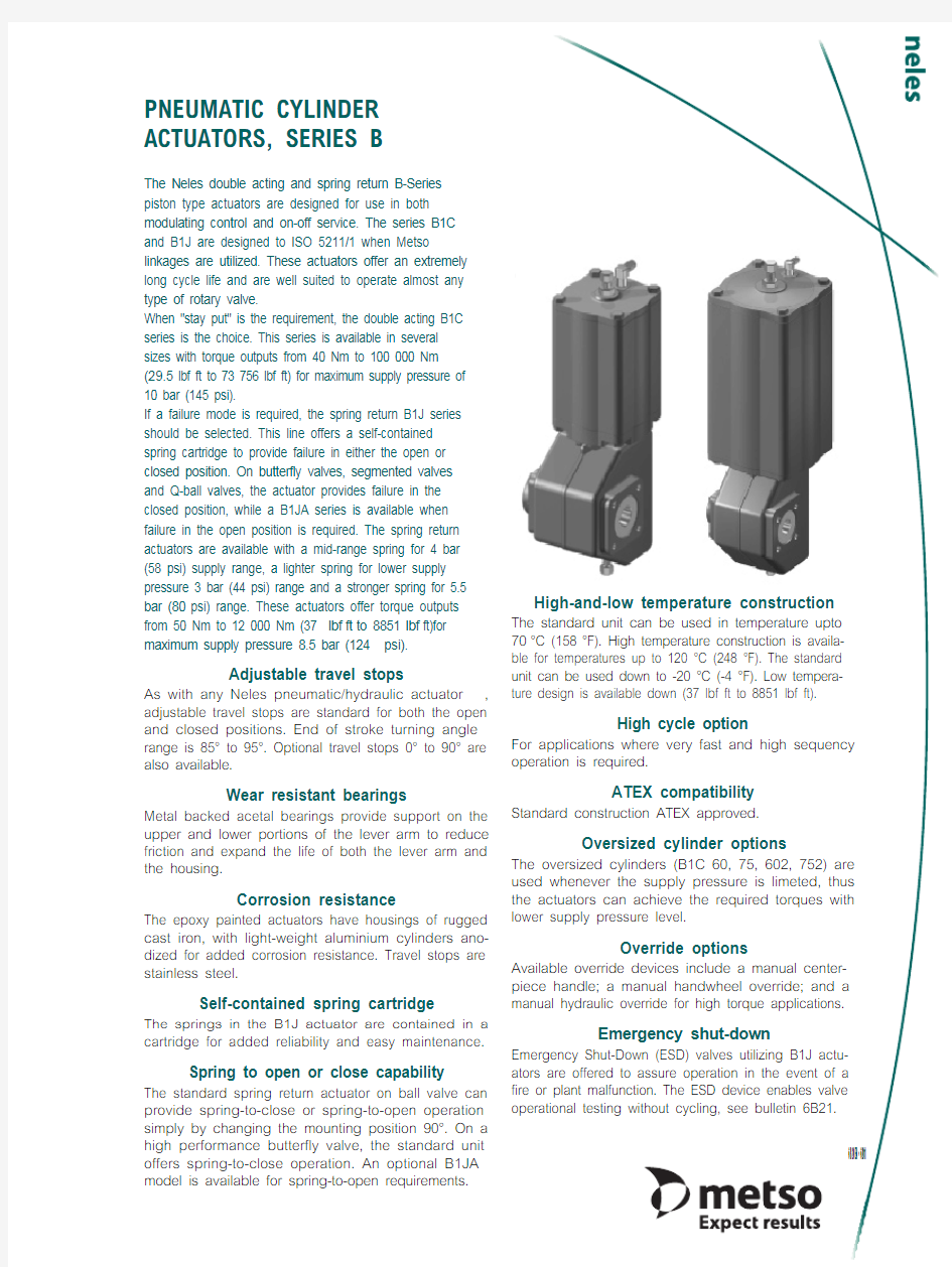
PNEUMATIC CYLINDER ACTUATORS, SERIES B
The Neles double acting and spring return B-Series piston type actuators are designed for use in both modulating control and on-off service. The series B1C and B1J are designed to ISO 5211/1 when Metso
linkages are utilized. These actuators offer an extremely long cycle life and are well suited to operate almost any type of rotary valve.
When "stay put" is the requirement, the double acting B1C series is the choice. This series is available in several sizes with torque outputs from 40 Nm to 100 000 Nm (29.5lbf ft to 73 756 lbf ft) for maximum supply pressure of 10 bar (145 psi).
If a failure mode is required, the spring return B1J series should be selected. This line offers a self-contained spring cartridge to provide failure in either the open or closed position. On butterfly valves, segmented valves and Q-ball valves, the actuator provides failure in the closed position, while a B1JA series is available when failure in the open position is required. The spring return actuators are available with a mid-range spring for 4 bar (58 psi) supply range, a lighter spring for lower supply pressure 3 bar (44 psi) range and a stronger spring for 5.5 bar (80psi) range. These actuators offer torque outputs from 50 Nm to 12 000 Nm (37lbf ft to 8851lbf ft)for maximum supply pressure 8.5 bar (124psi).
Adjustable travel stops
As with any Neles pneumatic/hydraulic actuator ,adjustable travel stops are standard for both the open and closed positions. End of stroke turning angle range is 85° to 95°. Optional travel stops 0° to 90° are also available.
Wear resistant bearings
Metal backed acetal bearings provide support on the upper and lower portions of the lever arm to reduce friction and expand the life of both the lever arm and the housing.
Corrosion resistance
The epoxy painted actuators have housings of rugged cast iron, with light-weight aluminium cylinders ano-dized for added corrosion resistance. Travel stops are stainless steel.
Self-contained spring cartridge
The springs in the B1J actuator are contained in a cartridge for added reliability and easy maintenance.
Spring to open or close capability
The standard spring return actuator on ball valve can provide spring-to-close or spring-to-open operation simply by changing the mounting position 90°. On a high performance butterfly valve, the standard unit offers spring-to-close operation. An optional B1JA model is available for spring-to-open requirements.
High-and-low temperature construction
The standard unit can be used in temperature upto 70°C (158°F). High temperature construction is availa-ble for temperatures up to 120 °C (248 °F). The standard unit can be used down to -20 °C (-4 °F). Low tempera-ture design is available down (37 lbf ft to 8851 lbf ft).
High cycle option
For applications where very fast and high sequency operation is required.
ATEX compatibility
Standard construction ATEX approved.
Oversized cylinder options
The oversized cylinders (B1C 60, 75, 602, 752) are used whenever the supply pressure is limeted, thus the actuators can achieve the required torques with lower supply pressure level.
Override options
Available override devices include a manual center-piece handle; a manual handwheel override; and a manual hydraulic override for high torque applications.
Emergency shut-down
Emergency Shut-Down (ESD) valves utilizing B1J actu-ators are offered to assure operation in the event of a fire or plant malfunction. The ESD device enables valve operational testing without cycling, see bulletin 6B21.
M E T S O
6 B 20E N
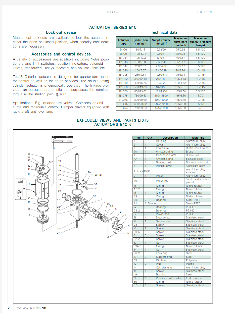
ACTUATOR, SERIES B1C
EXPLODED VIEWS AND PARTS LISTS
ACTUATORS B1C 6
Lock-out device
Mechanical lock-outs are available to lock the actuator in either the open or closed position, when security considera-tions are necessary .
Acessories and control devices
A variety of accessories are available including Neles posi-tioners and limit switches, position indicators, solenoid valves, transducers, relays, boosters and volume tanks etc.The B1C-series actuator is designed for quarter-turn action for control as well as for on-off services. The double-acting cylinder actuator is pneumatically operated. The linkage pro-vides an output characteristic that surpasses the nominal torque at the starting point (β = 0°).
Applications: E.g. quarter-turn valves. Compressor anti-surge and recirculate control. Damper drivers equipped with rack, shaft and lever arm.
Technical data
Actuator type Cylider bore mm/inch Swept volume liters/in 3
Maximum shaft bore mm/inch Maximum supply pressure
bar/psi
B1C680/3.150.33/2025/0.988.5/120B1C9100/3.940.60/3735/1.388.5/120B1C11125/4.92 1.10/6740/1.578.5/120B1C13160/6.30 2.30/14055/2.178.5/120B1C17200/7.87 4.30/26255/2.178.5/120B1C20200/7.87 5.40/32970/2.7610/145B1C25250/9.8410.50/64095/3.7410/145B1C32315/12.4021/1280105/4.1310/145B1C40400/15.7543/2620120/4.7210/145B1C50500/19.6984/5130135/5.3110/145B1C60600/23.62121/7380165/6.508.5/120B1C75750/29.53189/11500165/6.505/70B1C502500/19.69195/11900165/6.5010/145B1C602600/23.62282/17200165/6.508.5/120B1C752
750/29.53
441/26900
165/6.50
5/70
P N E U M A T I C C Y L I N D E R A C T U A T O R S , S E R I E S B
TECHNICAL BULLETIN 6/11
3
6 B 20E N Item Qty Description Materials
1 1 Housing Cast iron
2 1 Cover
Cast iron
3 1 Lever arm
Ductile iron + nickel 3A 1 Antistatic ring Brass 4 2 Connection arm
Ductile iron 4A 1 Antistatic ring Stainless steel 5 1 Bearing unit Ductile iron + nickel 6 1 Cylinder base Ductile iron 7 1 Pointer cover Aluminium alloy 8 1 Cylinder Aluminium alloy , anodized 9 1 Piston Cast iron
10 1 Piston rod Steel, hard chrome plated 16 1 O-ring
Nitrile rubber 17 2 O-ring Nitrile rubber 18 1 O-ring
Nitrile rubber 19 2 O-ring Nitrile rubber
20 2 Bearing Steel+PTFE, Bronze+PTFE 21 2 Bearing Steel+PTFE, Bronze+PTFE 22 1, 2 Bearing PE-HD 23 2 Bearing PE-HD 24 2,3 Piston seal
PE-HD 25
2
Bushing
Stainless steel
Item Qty Description
Materials 26 1 Stop screw
Stainless steel 27 1 Stop screw Stainless steel 281Screw Steel, zinced 29 1 Screw Steel, zinced 30 4 Screw Stainless steel 31 8,12 Screw Stainless steel 32 2 Screw Stainless steel 33 1 Nut Stainless steel 33A 1
O-ring Nitrile rubber 34 1 Nut Stainless steel 35 1 Lock nut Steel 36 2 Lock ring Steel 37 2 Support ring Steel 39 1
ID plate Polyester
41 Plug
Stainless steel 42 Plug Plastic 44 1 Cylinder end Ductile iron 471Torsion arm Steel 48 2
Washer
Steel 581Pressure outlet valve EPDM rubber 611Direction arrow Aluminium alloy 62
1
Screw
Stainless steel
M E T S O 4TECHNICAL BULLETIN 6/116B20E N
Item Qty Description Materials
1 1 Housing Steel
2 1 Cover Steel
3 1 Lever arm Ductile iron + nickel
3A 1 Antistatic ring Brass
4 2 Connection arm Ductile iron
4A 1 Antistatic ring Stainless steel
5 1 Bearing unit Ductile iron + nickel
6 1 Cylinder base Ductile iron
7 1 Pointer
cover Aluminium
alloy
8 1 Cylinder Aluminium alloy, anodized
9 1 Piston Cast
iron
10 1 Piston rod Steel, hard chrome plated 161O-ring Nitrile rubber
17 2 O-ring Nitrile rubber
18 1 O-ring Nitrile
rubber
19 2 O-ring Nitrile rubber
20 2 Bearing Bronze
net+PTFE
21 2 Bearing Bronze net+PTFE
22 2 Bearing PE-HD
23 2 Bearing PE-HD
24 3,
4 Piston
seal PE-HD
25 2 Bushing Stainless steel
26 1 Stop screw Stainless steel
Item Qty Description Materials 27 1 Stop screw Stainless steel
281Screw Steel, zinced
29 1 Screw Steel,
zinced
30 6 Screw Stainless steel
31 6Stud Steel,
zinced
32 2 Screw Stainless steel
33 1 Nut Stainless
steel
33A 1 O-ring Nitrile rubber
34 1 Nut Stainless
steel
35 1 Lock nut Steel
36 2 Lock
ring Steel
37 2 Support ring Steel
39 1 ID
plate Polyester
41 Plug Stainless steel
42 Plug Plastic
44 1 Cylinder end Ductile iron
456Nut Steel, zinced
466Washer Steel, zinced
471Torsion arm Steel
482Washer Steel
58 1 Pressure outlet valve EPDM Rubber
61 1 Direction arrow Aluminium alloy
62 1 Screw Stainless
steel
P N E U M A T I C C Y L I N D E R A C T U A T O R S , S E R I E S B
TECHNICAL BULLETIN 6/11
5
6 B 20E N Item Qty Description
Materials 1 1Housing Steel 2 1 Cover
Steel
3 1 Lever arm Ductile iron + nickel 3A 1 Antistatic ring Brass
4 4 Connection arm
Ductile iron 4A 1 Antistatic ring Stainless steel 5 2 Bearing unit Ductile iron + nickel 6 2 Cylinder base Ductile iron 7 1 Pointer cover Aluminium alloy
8 2 Cylinder Aluminium alloy , anodized 9 2 Piston Cast iron
10 2 Piston rod Steel, hard chrome plated 16 2 O-ring
Nitrile rubber 17 2 O-ring Nitrile rubber 18 2 O-ring
Nitrile rubber 19 4 O-ring Nitrile rubber 20 4 Bearing Bronze net+PTFE 21 4 Bearing Bronze net+PTFE 22 4 Bearing PE-HD 23 2 Bearing PE-HD 24 8 Piston seal
PE-HD 25 2 Bushing Stainless steel 26
2
Stop screw
Stainless steel
Item Qty Description Materials
27 2 Stop screw Stainless steel 28 2 Screw Steel, zinced 29 2 Screw Steel, zinced 30 20 Screw Stainless steel 31 12 Stud Steel, zinced 32 2 Screw Stainless steel 33 2 Nut Stainless steel 33A 2 O-ring
Nitrile rubber 34 2 Nut
Stainless steel 35 2 Lock nut Steel 36 4 Lock ring Steel 37 4 Support ring Steel 39 1 ID plate Polyester 41 4 Plug Stainless steel 42 4 Plug Plastic 44 2 Cylinder end Ductile iron 45 12 Nut
Steel, zinced 46 12 Washer
Steel, zinced 58 1 Pressure outlet valve EPDM rubber 61 1 Direction arrow Aluminium alloy 62 2 Screw Stainless steel 63
2
Pin
Steel 65 4 Pin
Steel
M E T S O 6
TECHNICAL BULLETIN 6/11
6 B 20E N
DOUBLE ACTING ACTUATOR, SERIES B1C
OPERATION
The linkage mechanism within the B-series actuator converts linear motion of the piston into a 90° (max. 98°) rotation of the actuator shaft. The line in the figure to the right shows torque characteristics vs. actuator shaft angle.
Max. torque is achieved at β = 0° which usually corre-sponds to the closed position of ball and butterfly valves and where max. seat torque normally appears.
Another peak is achieved at 60-80° which corresponds to the dynamic torque peak of butterfly valves. The torque’s in the table below show the minimum torque Mn at different supply pressures.
SELECTION
T o select the proper actuator for a particular valve and serv-ice, first determine the maximum operating torque that will be required for the valve from the applicable valve torque table,then refer to the appropriate mode of operation of the actua-tor in the torque output tables below and select the actuator that will, at the available air supply pressure, provide a torque output no less than the required operating torque for the valve. If in doubt, select the next larger actuator .
ACTUATOR TORQUE M n
Note:
The actuator can be used at higher supply pressures than shown in the table.
Maximum supply pressures are listed in the table on page 2.
Example 1.
Required torque: 130 Nm / 98 lbf ft.
Air supply pressure ps = 4.8 bar /70 psi.On-off service.
B1C9 output torque is 140 Nm / 104 lbf ft.Select B1C9
B1C attachment according to the ISO 5211.Actuator
type
Torque Output Mn Nm - ft-lbs at Specific Supply Pressure bar - psi
3.0 bar
43 psi 3.5 bar 50 psi 4 bar 58 psi 5 bar 72 psi 5.5 bar 80 psi 6 bar 87 psi 7 bar 102 psi Nm lbf ft Nm lbf ft Nm lbf ft Nm lbf ft Nm lbf ft Nm lbf ft Nm lbf ft B1C 645305138604575558260906510075B1C 985601007511590145110160120175130205150B1C11160120185137220160270200300220330240375280B1C13330245390290460335565415620460675505790585B1C1762046072053085062510407801160850126093015701085B1C2075056088065010307601290940140010401550114017801320B1C2514501070170012502010146025001830270020003000223034502540B1C3228902140340025004000293050003650550041006000445070005170B1C406100449071005200829061501031076001130084001229091001430010550B1C50117708770139001020016290120002021014900220001630024190178102810020700B1C60173301198020300150002371017460295802177032400
23900
35320
26030
41190
30440
B1C752718020010317002340037170274204625034060B1C5022654019580310002290036290268304479033330496003660054500398706300046460B1C602382002814044600329005220038540651104802071400
52700
77710
57290
90490
66750
B1C752
60240
44410
70300
51900
82340
60680
102710
75630
P N E U M A T I C C Y L I N D E R A C T U A T O R S , S E R I E S B
TECHNICAL BULLETIN 6/11
7
6 B 20E N
ACTUATOR, SERIES B1J
EXPLODED VIEWS AND PARTS LISTS
ACTUATORS B1J 8-20
The B1J-series actuator is designed for quarter turn action for control as well as for on-off services. The spring-return cylinder actuator is pneumatically operated. The linkage pro-vides an output characteristic that surpasses the nominal torque at the starting point (β = 0°).
Applications: E.g. quarter-turn valves.
Damper drivers equipped with rack, shaft and lever arm.
Actuator type Cylider bore mm/inch Swept volume liters/in 3Maximum shaft bore mm/inch Maximum supply pressure bar/psi B1J8125/4.920.9/5535/1.388.5/120B1J10160/6.30 1.80/11140/1.578.5/120BJ12200/7.87 3.60/22555/2.178.5/120B1J16250/9.84 6.70/41555/2.178.5/120B1J20315/12.4013/79570/2.768.5/120B1J25400/15.7527/164295/3.748.5/120B1J32500/19.6953/3231105/4.138.5/120B1J322
500/19.69
106/6480
120/4.72
8.5/120
M E T S O 8TECHNICAL BULLETIN 6/116B20E N
Item Qty Description Materials
1 1 Housing Cast
iron
2 1 Cover Cast iron
3 1 Lever arm Ductile iron + nickel
3A 1 Antistatic ring Brass
4 2 Connection
arm Ductile
iron
4A 1 Antistatic ring Stainless steel
5 1 Bearing unit Ductile iron + nickel
6 1 Cylinder base Ductile iron
7 1 Pointer
cover Aluminium
alloy
8 1 Cylinder Aluminium alloy, anodized
9 1 Piston Cast
iron
10 1 Piston rod Steel, hard chrome plated 111Spring Steel
121Spring plate Steel, zinced
131Clamping tube Steel
14 2 Lock ring Steel
151Hexagon nut Steel
16 1 O-ring Nitrile rubber
17 2 O-ring Nitrile
rubber
18 1 O-ring Nitrile rubber
19 1 O-ring Nitrile
rubber
20 2 Bearing Steel+PTFE, Bronze+PTFE 212Bearing Steel+PTFE, Bronze+PTFE
22 1, 2 Bearing PE-HD
23 2 Bearing PE-HD
Item Qty Description Materials 24 3,
4Piston
seal PE-HD
25 2 Bushing Stainless steel
26 1 Stop
screw Stainless
steel
27 1 Stop screw Stainless steel
29 1Screw Steel,
zinced
30 4 Screw Stainless steel
31 6 Stud Steel,
zinced
32 2 Screw Stainless steel
33 1Nut Stainless
steel
33A 1O-ring Nitrile rubber
34 1Nut Stainless
steel
35 1Lock nut Steel
36 2 Lock
ring Steel
37 2 Support ring Steel
39 1 ID
plate Polyester
401Filter Stainless steel
41 4 Plug Stainless
steel
42 1 Plug Plastic
431Warning plate Aluminium sticker 44 2 Cylinder end Ductile iron
456Nut Steel, zinced
466Washer Steel, zinced
58 1 Pressure outlet valve EPDM rubber
61 1 Direction arrow Aluminium plate
62 1 Screw Stainless
steel
P N E U M A T I C C Y L I N D E R A C T U A T O R S , S E R I E S B
TECHNICAL BULLETIN 6/11
9
6 B 20E N Item Qty Description
Materials 1 1 Housing
Steel 2 1 Cover
Steel
3 1 Lever arm Ductile iron + nickel 3A 1 Antistatic ring Brass
4 4 Connection arm
Ductile iron 4A 1 Antistatic ring Stainless steel 5 2 Bearing unit Ductile iron + nickel 6 2 Cylinder base Ductile iron 7 1 Pointer cover
Aluminium alloy 8 2 Cylinder Aluminium alloy , anodized 9 2 Piston
Cast iron
10 2 Piston rod Steel, hard chrome plated 112Spring Steel 122Spring plate Steel 132Clamping tube Steel 144Lock ring Steel 152Hexagon nut Steel 16 2 O-ring Nitrile rubber 17 2 O-ring Nitrile rubber 18 2 O-ring Nitrile rubber 19 4 O-ring
Nitrile rubber 20 4 Bearing Bronze net+PTFE 21 4 Bearing
Bronze net+PTFE 22 2 Bearing PE-HD 23 2 Bearing PE-HD 24
8
Piston seal
PE-HD 25 2 Bushing
Stainless steel
Item Qty Description
Materials
26 2 Stop screw Stainless steel 27 2 Stop screw Stainless steel 29 2 Screw Steel, zinced 30 16 Screw Stainless steel 31 12 Stud Steel, zinced 32 2 Screw Stainless steel 33 2 Nut Stainless steel 33A 2 O-ring Nitrile rubbe 34 2 Nut Stainless steel 35 2 Lock nut Steel 36 4 Lock ring Steel 37 4 Support ring Steel 39 1 ID plate Polyester 402Filter Stainless steel 41 4 Plug
Stainless steel 42 2 Plug
Plastic
432Warning plate Aluminium sticker 44 2 Cylinder end Ductile iron 45 12
Hexagon nut Steel, zinced 46 12 Washer
Steel, zinced 58 1 Pressure outlet valve EPDM rubber 61 1 Direction arrow Aluminium alloy 62 2 Screw
Stainless steel 632Pin Steel 65
4
Pin
Steel
M E T S O 10TECHNICAL BULLETIN 6/116B20E N
Item Qty Description Materials
1 1 Housing Cast
iron
2 1 Cover Cast iron
3 1 Lever arm Ductile iron + nickel
3A 1 Antistatic ring Brass
4 2Connection arm Ductile iron
4A 1 Antistatic ring Stainless steel
5 1Bearing unit Ductile iron + nickel
6 1 Cylinder base Ductile iron
7 1 Pointer
cover Aluminium
alloy
8 1 Cylinder Aluminium alloy, anodized 91Piston Cast iron
101Piston rod Steel, hard chrome plated 111Spring Steel
121Spring plate Steel, zinced
131Clamping tube Steel
14 2 Lock ring Steel
151Hexagon nut Steel
16 1 O-ring Nitrile rubber
17 2 O-ring Nitrile
rubber
18 1 O-ring Nitrile rubber
19 1 O-ring Nitrile
rubber
20 2 Bearing DU-type, steel+PTFE
21 2Bearing DU-type,
steel+PTFE
Item Qty Description Materials
22 1 Bearing PE-HD
23 2 Bearing PE-HD
24 3 Piston
seal PE-HD
25 2 Bushing Stainless steel
29 1 Screw Steel,
zinced
30 4 Screw Stainless steel
31 8, 12 Screw Stainless steel
32 2 Screw Stainless steel
33 1 Nut Stainless
steel
33A 1 O-ring Nitrile rubber
34 1 Nut Stainless
steel
35 1 Lock nut Steel
36 2 Lock
ring Steel
37 2 Support ring Steel
39 1 ID
plate Polyester
41 4Plug Stainless steel
42 1 Plug Plastic
431Warning plate Plastic
44 1 Cylinder
end Ductile
iron
581Pressure outlet valve EPDM rubber
611Direction arrow Aluminium alloy 621Screw Stainless steel
P N E U M A T I C C Y L I N D E R A C T U A T O R S , S E R I E S B
TECHNICAL BULLETIN 6/11
11
6 B 20E N Item Qty Description Materials
1 1Housing Cast iron
2 1 Cover Cast iron
3 1 Lever arm Ductile iron + nickel 3A 1 Antistatic ring Brass
4 2 Connection arm
Ductile iron 4A 1 Antistatic ring Stainless steel 5 1 Bearing unit Ductile iron + nickel 6 1 Cylinder base Ductile iron 7 1 Pointer cover
Aluminium alloy 8 1 Cylinder Aluminium alloy , anodized 9 1 Piston
Cast iron
10 1 Piston rod Steel, hard chrome plated 111Spring Steel
121Spring plate Steel 131Clamping tube Steel 14 2 Lock ring Steel 151Hexagon nut Steel 16 1 O-ring Nitrile rubber 17 2 O-ring Nitrile rubber 18 1 O-ring Nitrile rubber 19 1
O-ring Nitrile rubber
20 2 Bearing Steel+PTFE, Bronze net+PTFE 21 2 Bearing
Steel+PTFE, Bronze net+PTFE 22
1, 2
Bearing
PE-HD 23 2 Bearing
PE-HD
Item Qty Description Materials
24 3, 4 Piston seal PE-HD
25 2 Bushing Stainless steel 26 1 Stop screw Stainless steel 27 1 Stop screw Stainless steel 29 1Screw Steel, zinced 30 4 Screw Stainless steel 31 6
Stud Steel, zinced 32 2 Screw Stainless steel 33 1 Nut Stainless steel 33A 1 O-ring Nitrile rubber 34 1 Nut Stainless steel 35 1 Lock nut Steel 36 2 Lock ring Steel 37 2 Support ring Steel 39 1 ID plate Polyester 401Filter Stainless steel 41 4
Plug Stainless steel 42 1Plug
Plastic 431Warning plate Plastic 441Cylinder end Ductile iron 456Nut Steel, zinced 466Washer
Steel, zinced 581Pressure outlet valve EPDM rubber 611Direction arrow Aluminium plate 62
1
Screw
Stainless steel
M E T S O 12TECHNICAL BULLETIN 6/116B20E N
Item Qty Description Materials
1 1 Housing Steel
2 1 Cover Steel
3 1 Lever arm Ductile iron+nickel
3A 1 Antistatic ring Brass
4 4 Connection arm Ductile iron
4A 1 Antistatic ring Stainless steel
52Bearing unit Ductile iron+nickel
6 2 Cylinder base Ductile iron
7 1 Pointer cover Aluminium alloy
8 1 Cylinder Aluminium alloy, anodized
9 2 Piston Cast
iron
10 2 Piston rod Steel, hard chrome plated 112Spring Steel
122Spring plate Steel
132Clamping tube Steel
144Lock ring Steel
152Hexagon nut Steel
16 2 O-ring Nitrile rubber
17 2 O-ring Nitrile
rubber
18 2 O-ring Nitrile rubber
19 4 O-ring Nitrile
rubber
20 4 Bearing Bronze net+PTFE
21 4 Bearing Bronze
net+PTFE
22 2 Bearing PE-HD
23 2 Bearing PE-HD
24 8 Piston seal PE-HD
252Bushing Stainless steel
Item Qty Description Materials 26 2 Stop
screw Stainless
steel
27 2 Stop screw Stainless steel
29 2 Screw Steel,
zinced
30 16 Screw Stainless steel
31 12 Stud Steel,
zinced
32 2 Screw Stainless steel
33 2 Nut Stainless
steel
33A 2 O-ring Nitrile rubber
34 2 Nut Stainless
steel
352Lock nut Steel
36 4 Lock
ring Steel
37 4 Support ring Steel
39 1 ID
plate Polyester
402Filter Stainless steel
414Plug Stainless steel
42 2 Plug Plastic
432Warning plate Aluminium sticker 44 2 Cylinder end Ductile iron
452Hexagon nut Steel, zinced
46 2 Washer Steel, zinced
58 1 Pressure outlet valve EPDM rubber
61 1 Direction arrow Aluminium plate 622Screw Stainless steel
632Pin Steel
654Pin Steel
P N E U M A T I C C Y L I N D E R A C T U A T O R S , S E R I E S B
TECHNICAL BULLETIN 6/11
13
6 B 20E N SINGLE ACTING ACTUATOR SERIES B1J
OPERATION
The linkage converts linear motion of the piston into a 90° (max. 98°) rotation of the actuator shaft. As a result of the link-age design, the relationship between output torque and piston force depends on the angle of the actuator shaft. The torque output values in the table below show the minimum spring torque (Ms)and the minimum torque (Mp) produced as a result of a specific supply pressure and spring.
ACTUATOR SELECTION
T o select the proper actuator for a par-ticular valve and service, first determine the maximum operating torque that will be required for the valve from the appli-cable valve torque table, then refer to the appropriate mode of operation of the actuator in the torque output tables below and select the actuator that will, at the available air supply pressure, pro-vide a torque output no less than the required operating torque for the valve. If in doubt, select the next larger actuator .
ACTUATOR TORQUE, M n
B1J attachment according to the ISO 5211.
Note: Maximum allowed supply pressure is 120 psi (8.5 bar).B1JK_ has a lighter spring for lower supply pressures.B1J_ for medium supply pressures
B1JV_ has a stronger spring for higher supply pressures.Torque outputs for B1J are identical to those shown for BJ.
GENERAL SELECTIONS GROUNDS
The first selection ground for actuator sizing must always be the torque given by the spring.
Secondly , it must be checked that the available pressure is sufficient to give at least the same torque as the spring, but in the opposite direction.
Note: Max. supply pressure 8.5 bar / 120 psi.Mn =Nominal running torque
M spring =Torque developed by the spring force. Mp =T orque developed by the difference of pressure
force and spring force (eg. M 5 = torque devel-opped with 5 bar). When α = 0° the valve is closed.Example 1.
Required torque:130 Nm / 98 lbf ft.Required action:Spring-to-close.
Nominal spring torque, Ms B1J10 = 150 Nm / 110 lbf ft.Select B1J10.Note:Min. air supply pressure ps = 4.1 bar /
60psi.
Example 2.
Required torque:500 Nm / 370 lbf ft.Required action:Spring-to-open.Step 1.
At the turning angle ? = 90° (valve is fully open), the nominal spring torque B1JA16is 600 Nm / 440 lbf ft.
Step 2.
When air closes the valve (? = 0°) the actu-ator torque (B1JA16) is 650Nm / 480 lbf ft at 4.1 bar / 60 psi supply pressure.Select B1JA16.Note:
At air supply pressures ps < 4.1bar /60psi, contact factory .
Actuator type
Spring min torque
Mn Nm lbf ft B1JK8, B1JKA85037B1J8, B1JA87050B1JV8, B1JVA89066B1JK10, B1JKA1010577B1J10, B1JA10150110B1JV10, B1JVA10200150B1JK12, B1JKA12210155B1J12, B1JA12300220B1JV12, B1JVA12390290B1JK16, B1JKA16420310B1J16, B1JA16600440B1JV16, B1JVA16780575B1JK20, B1JKA20850630B1J20, B1JA201200880B1JV20, B1JVA2015001100B1JK25, B1JKA2517001250B1J25, B1JA2524001760B1JV25, B1JVA2530002200B1JK32, B1JKA3234002500B1J32, B1JA3248003500B1JV32, B1JVA3261004500B1JK322, B1JKA32268005000B1J322, B1JA32296007000B1JV322, B1JVA322
12200
9000
Spring to close, type B1J
Spring to open, type B1JA
M E T S O 14
TECHNICAL BULLETIN 6/11
6 B 20E N
SPECIAL CONTRUCTIONS
LOCKING DEVICE For service assembly
Type code: B1C_DD On housing end
Type code: B1_Q On cylinder end
Type code: B1_W
SHOCK ABSORBER ON HOUSING END Type code: B1C_N AUTOMATIC LATCHING DEVICE FOR CLOSED POSITION Type code: B1C_P MANUAL LATCHING
Type code: B1_T
HANDWHEEL On cylinder end
Type code: B1C_K
Type code: B1C_L HYDRAULIC MANUAL OVERRIDE
Type code: B1CH
P N E U M A T I C C Y L I N D E R A C T U A T O R S , S E R I E S B
6 B 20E N DIMENSIONAL DRAWINGS
ACTUATORS B1C
SPRING RETURN ACTUATORS B1J, B1JA
B1C
Type Dimensions, mm
NPT kg X G F V Y L
K1R1B1C690270395364680138801/44,2B1C9110315450435080140811/49,6B1C11135375535515095154893/816B1C1317544564065651201901093/831B1C1721555578578701372221261/254B1C2021559088097801452621471/273B1C2526572510751211101803041661/2131B1C3239592013701531462803792043/4256B1C40505115016701941853204492243/4446B1C50610139020602421953505432681830B1C607251390206024219535054326811080B1C758751390206024219535054326811190Type Dimensions, inch NPT lbs X G F V Y L K1R1B1C6 3.5410.6015.60 1.42 1.81 3.15 5.43 3.151/49B1C9 4.3312.4017.70 1.69 1.97 3.15 5.51 3.191/421B1C11 5.3114.8021.10 2.01 1.97 3.74 6.06 3.503/835B1C13 6.8917.5025.20 2.56 2.56 4.727.48 4.293/868B1C178.4621.9030.90 3.07 2.76 5.398.74 4.961/2119B1C208.4623.2034.70 3.82 3.15 5.7110.31 5.791/2161B1C2510.4328.5042.30 4.76 4.337.0911.97 6.541/2289B1C3215.5536.2053.90 6.02 5.7511.014.928.033/4564B1C4019.8845.3065.707.647.2812.6017.688.823/4983B1C5024.0254.7081.109.537.6813.7821.3810.5511829B1C6028.5454.7081.109.537.6813.7821.3810.5512380B1C75
34.45
54.70
81.10
9.537.68
13.78
21.38
10.55
1
2620
B1J, B1JA
Type Dimensions, mm
NPT kg X G F V Y L K1R1B1J, B1JA8135420555435080140813/817B1J, B1JA10175480640515095154893/830B1J, B1JA1221562081565651201901091/257B1J, B1JA1626576099078701372221261/2100B1J, B1JA20395940123097801452621473/4175B1J, B1JA25505114014901211101803041663/4350B1J, B1JA32
540
1435
1885
153
146
280
379
204
1671Type Dimensions, inch
NPT lbs X G F V Y L K1R1B1J, B1JA8 5.3116.5021.90 1.69 1.97 3.15 5.51 3.193/837B1J, B1JA10 6.8918.9025.20 2.01 1.97 3.74 6.06 3.503/866B1J, B1JA128.4624.4032.10 2.56 2.56 4.727.48 4.291/2126B1J, B1JA1610.4329.9038.00 3.07 2.76 5.398.74 4.961/2220B1J, B1JA2015.5537.0048.40 3.82 3.15 5.7110.31 5.793/4386B1J, B1JA2519.8844.9058.70 4.76 4.337.0911.97 6.543/4771B1J, B1JA32
21.26
56.50
74.20
6.02
5.75
11.0
14.92
8.03
1
1479
M E T S O 16
TECHNICAL BULLETIN 6/11
6 B 20E N
B1JR/B1JRR
B1JAR/B1JARR
Type Dimensions, mm
kg X Z G F H I J V Y L K1R1B1JR8135250570705---4350801408119B1JR10175250695
855
---515095
154
89
33B1JR12215250
8051000---6565120190109
60
B1JR1626540010801310---7870137222126106B1JRR203952001455174586848.2523097
80
145262147210
B1JRR2550525016652015107448.25280121110180304166380B1JRR32540
40018952345130648.25375
153146280379204705
Type Dimensions, inch
lbs X Z G
F
H I J V Y L K1R1B1JR8 5.39.822.427.8--- 1.7 2.0 3.1 5.5 3.242B1JR10 6.99.827.433.7--- 2.0 2.0 3.7 6.1 3.573B1JR128.5
9.831.739.4
--- 2.6 2.6 4.77.5 4.3132B1JR16
10.415.742.551.6
--- 3.1 2.8 5.48.7 5.0233B1JRR2015.67.957.368.734.2 1.99.1 3.8 3.1 5.710.3 5.8463B1JRR2519.9
9.8
65.679.342.3
1.911.0 4.8 4.3
7.1
12.0
6.5
837
B1JRR3221.315.774.692.351.4 1.9
14.8
6.0
5.7511.014.98.01553
Type Dimensions, mm
NPT kg X
Z
G
F H I J V Y L K1R1B1JAR8135250420720---435080140813/820B1JAR10175250480
870
---515095
154
89
3/8
30B1JAR122152506201030---65651201901091/2
55
B1JAR16
2654007601345
---78701372221261/2100B1JARR20395200940178528548.25175
97
80
1452621473/4210
B1JARR255052501140202531448.251851211101803041663/4380
B1JARR325404001435238538148.252401531462803792041
705
Type Dimensions, inch
NPT lbs X Z
G
F
H I J V Y L K1R1B1JAR8 5.39.816.528.3--- 1.7 2.0 3.1 5.5 3.23/844B1JAR10 6.99.818.934.3--- 2.0 2.0 3.7 6.1 3.53/8
66
B1JAR12
8.5
9.824.440.6
--- 2.6 2.6 4.77.5 4.31/2121B1JAR1610.415.729.953.0
--- 3.1 2.8 5.4
8.7
5.0
1/2220B1JARR2015.67.937.070.311.2 1.9 6.9 3.8 3.1 5.710.3 5.83/4463B1JARR2519.99.844.979.712.4 1.9
7.3 4.8
4.3
7.112.0 6.5
3/4837B1JARR3221.315.756.593.915.0 1.99.4
6.0 5.7511.014.98.0
1
1553
B1JH
Type Dimensions, mm
NPT kg X
G
F
E N
V
Y
L K1R1S B1JH813558572051772043508014081803/830B1JH1017563079055274051509515489803/843B1JH1221574594062376565651201901091201/270B1JH16265940117066580078701372221261201/2115B1JH203951075136578588097801452621471453/4190B1JH25505140517559109551211101803041661803/4370B1JH3254016352085
1245
850153146
280
379
204
210
1
700
Type Dimensions, inch
NPT lbs X G F E N V Y L K1R1S B1JH8 5.3123.0328.320.3528.35 1.69 1.97 3.15 5.5 3.2 3.153/866B1JH10 6.8924.8031.121.7329.13 2.01 1.97 3.7461 3.5 3.153/895B1JH128.4629.3337.024.5330.12 2.56 2.56 4.727.5 4.3 4.721/2154B1JH1610.4337.0146.126.1831.50 3.07 2.76 5.398.7 5.0 4.721/2253B1JH2015.5542.3253.730.9134.65 3.82 3.15 5.7110.3 5.8 5.713/4419B1JH2519.8855.3169.135.8337.60 4.76 4.337.0912.0 6.57.093/4815B1JH32
21.26
64.37
82.1
49.02
33.46
6.02
5.75
11.0
14.9
8.0
8.27
11543
B1JR/B1JRR
B1JAR/B1JARR
P N E U M A T I C C Y L I N D E R A C T U A T O R S , S E R I E S B
TECHNICAL BULLETIN 6/11
17
6 B 20E N B1CH 502, 602, 752
B1JH322
ACTUATOR B1C 502, 602, 752
ACTUATOR B1J 322
Type Dimensions, mm Dimensions, inch X 1X 2X 1X 250254061021.324.060263572525.028.5752
813
875
32.0
34.5
Type
kg lbs B1C 50216653663B1CH 50219504290B1C 60221704780B1C 75223005070B1J 32216503630B1JH 322
1685
3707
M E T S O 18
TECHNICAL BULLETIN 6/11
6 B 20E N
.
ACCESSORIES MOUNTING FACE DIMENSIONS
Actuator Dimensions, mm Mounting face B1C B1J O (H8)M P K (keyway)
L S U N 6
152025 4.764.766.3517.023.327.940
90
70
M8
4
F07
9
8
15202535 4.764.766.359.5217.023.327.939.3509070M84F07
111020253540 4.766.359.529.5223.327.939.344.460105102M104F10
13125512.7060.875130125M124F1217165512.7060.880120140M164F1420207019.05
78.3
105195140M164F1425259522.22105.5140235165M204F163232
10525.40116.3155280254M168F25409510512022.2225.4031.75105.5116.3133.9180
340298M208
F30
506075
12013531.7531.75133.9149.2200430356M308F35322
9510512022.2225.4031.75105.5116.3133.9180320298M208F30502602752
120135150165180
31.7531.7538.1038.1044.45
133.9149.2166.8182.0199.4
250470406M368F40
Actuator Dimensions, inch Mounting face B1C B1J
O
(H8)M
P
K (keyway)L S U N (pcs.)
6
0.590.790.980.190.190.250.67
0.921.10 1.57
3.54
2.76
M8
4
F07
9
8
0.590.790.981.38
0.190.190.250.370.670.921.101.55 1.97 3.54 2.76M84F07
11
100.790.981.38
1.57
0.190.250.370.37
0.921.101.551.75
2.36 4.13 4.02M104F10
1312 2.170.50 2.39 2.95 5.12 4.92M124F121716 2.170.50 2.39 3.15 4.72 5.51M164F142020 2.760.75 3.08 4.137.68 5.51M164F142525 3.740.87 4.15 5.519.25
6.50M20
4F163232 4.13 1.00 4.58
6.1011.0210.00M168F25409510512022.2225.4031.75105.5116.3133.9
7.09
13.3911.73M20
8
F30
506075
4.72
5.31 1.251.25 5.275.877.871
6.9314.02M308F35
322 3.744.134.720.871.001.25 4.154.58
5.27
7.0912.6011.73M208F30
502602752
4.72
5.315.91
6.50
7.09 1.251.251.501.501.75 5.275.876.577.177.85
9.8418.5015.98M368
F40
Actuator size
E F h2
63080458, 930804510, 1130804512, 133********, 17301305520301305525541605532541885540642605550
64
290
55
P N E U M A T I C C Y L I N D E R A C T U A T O R S , S E R I E S B
TECHNICAL BULLETIN 6/11
19
6 B 20E N Pneumatic double-acting cylinder actuator, Series B1C and BC
Signs 1, 2, 6 and 7 are obligatory: other marks are options 1. 2. 3. 4. 5. 6.7.8.9.10.11.B1
C
M
S
Y
U
50/120
H
E
X
M
1. sign PRODUCT GROUP B1Cylinder actuator with attachment dimensions acc. to ISO 5211B
Cylinder actuator with attachment dimensions acc. to internal standard (D 301691)
2. sign SERIES C
Double acting, pneumatic
3. sign CONSTRUCTIONS -Standard construction without sign H
Manual hydraulic override
4. sign CYLINDER AND HOUSING MATERIALS - Aluminium cylinder and GG-20 housing, standard materials, without sign
S Steel cylinder and GG-20 housing
B Alumium cylinder and GGG-40 housing and piston X
Steel cylinder and GGG-40 housing and piston
5. sign SPECIAL CONSTRUCTION -Standard construction without sign
Q Mechanical locking device for piston movement limit on housing end. Locking with long screw to close position.
W Mechanical locking device for piston movement limit on cylinder end. Locking with long screw to open position.
QW Mechanical locking device for piston movement limit on housing and cylinder ends. Locking with long screws to close as well as to open position.
G Actuator equipped with automatic latching device and shock absorber on housing end
DD Built-in manual locking device of actuator housing. Locking to close position. Maintenance locking device which keeps tightness of butterfly valves. Sizes 6, 502, 602 and 752 are excluded.N Actuator equipped with shock absorber on housing end P Actuator equipped with automatic latching device for closed position. Design is made mainly for actuator locking device of capping valve. No free motion.
T Actuator equipped with manual latching device. Actuator can be locked to open position allowing about 20 degrees' motion.K Handwheel on cylinder end L Handwheel on housing end
R Handwheel both on cylinder end and housing end
Y
Special, to be specified, e.g. special material or stop screw
6. sign INTERFACE FOR ADDITIONAL DEVICES (positioner, limit switch)
U
Interface engineered to VDI/VDE with the use of Metso linkages
7. sign ACTUATOR SIZE
E.g. 50/ 120 = actuator size / shaft bore diameter .
Note special sizes (BC 50 and 502 with oversized cylinder):60 - max. supply pressure 8.5 bar (cylinder ? 600 mm/24")75 - max. supply pressure 5 bar (cylinder ? 750 mm/30")602 - max. supply pressure 8.5 bar (cylinder ? 600 mm/24")752 - max. supply pressure 5 bar (cylinder ? 750 mm/30")
8. sign MATERIALS OF SEALS AND BEARINGS
–
Standard construction without sign (-20° to +70 °C)O-rings: Nitrile rubber .
Bearings and piston seals: PE-HD DU-bearings in sizes 6 to 25
Stainless steel net + PTFE bearings with antistatic ring in sizes 32 to 752
H High temperatures (-20° to +120 °C)Dynamic O-rings: Fluorocarbon rubber Bearings and piston seals: PTFE + C25C Low temperatures (-40° to +70 °C)Dynamic O-rings: Epiclohydrin rubber Bearings and piston seals: PTFE + C25F Oversized NPT connections: fast operation F1Large oversized NPT connections: faster operation L
Long-run option
High cycle bearings: Fiberglide with antistatic ring Special piston rod seal: Double Delta; O-ring + PTFE D DU-bearings
For sizes 32 to 502
9. sign SCREW MATERIAL –Stainless steel (standard) without sign for sizes 6 through 32
Steel, zinc coated and passivated (standard) without sign for sizes 40 and bigger .
E
Stainless steel for sizes 40 and bigger .
10. sign
NON-STANDARD OPERATION RANGE e.g. 30° - 70°
(standard operation range e.g. for ball valves 0° - 90°, without sign)X Valve closed position is limited. When closed position is limited to 30°, X = 30 (never fully closed).
Z
Valve open position is limited. When open position is limited to 70°, Z = 70 (never fully open).
11. sign SPECIAL CONSTRUCTION M
K-mass fire protection
HOW TO ORDER
Subject to change without prior notice.
Metso Automation Inc.
Europe, Va n ha Po r voo n tie 229, P .O. Box 304, FI-01301 VANTAA, Fi n la n d.Tel. +358 20 483 150. Fax +358 20 483 151North America, 44 Bowditch D r ive, P .O. Box 8044, S h r ewsb ur y , MA 01545, U S A. Tel. +1 508 852 0200. Fax +1 508 852 8172
South America, Av . I n depe n dén cia, 2500- Ipo r a ng a, 18087-101, S o r ocaba-S ?o Pa u lo, B r azil. Tel. +55 15 2102 9700. Fax +55 15 2102 9748/49
Asia Pacific, 20 Kalla ng Ave nu e, Lobby B, #06-00, PICO C r eative Ce n t r e, S i ng apo r e 339411, S i ng apo r e.Tel. +65 6511 1011. Fax +65 6250 0830China, 19/F , the Excha ng e Beiji ng , No. 118, Jia ngu o L u Yi, Chaoya ng Dist, 100022 Beiji ng , Chi n a. Tel. +86-10-6566-6600. Fax +86-10-6566-2575Middle East, Ro un dabo u t 8, U n it AB-07, P .O. Box 17175, Jebel Ali F r eezo n e, D u bai, U n ited A r ab E m i r ates. Tel. +971 4 883 6974. Fax +971 4 883 6836
https://www.doczj.com/doc/f47825773.html,/valves
Signs 1, 2, 8 and 9 are obligatory , other signs are options 1. sign PRODUCT GROUP
B1Cylinder actuator with attachment dimensions acc. to
ISO 5211
B
Cylinder actuator with attachment dimensions acc. to internal standard (D 301691)2. sign SERIES J Pneumatic, spring-return 3. sign SPRING OPTIONS
-Standard construction without sign K Light spring V
Strong spring
4. sign FUNCTION CODE –Spring-to-close operation, without sign A Spring-to-open operation (L for old type)
5. sign CONSTRUCTION
-Standard construction without sign
R Secondary handwheel operation (sizes 8 - 16)
RR Secondary handwheel with wormgear (sizes 20 - 32)H
Manual hydraulic override
6. sign CYLINDER AND HOUSING MATERIALS
-Aluminium cylinder and GG-20 housing, standard materials, without sign S Steel cylinder and GG-20 housing B Aluminium cylinder and GGG-40 housing and piston X Steel cylinder and GGG-40 housing and piston 7. sign SPECIAL CONSTRUCTION -Standard construction without sign
Q
Mechanical locking device for piston movement limit on housing end. Locking with long screw to close position.W Mechanical locking device for piston movement limit on cylinder end. Locking with long screw to open position.
QW Mechanical locking device for piston movement limit on
housing and cylinder ends. Locking with long screws to
close as well as to open position.
PP Actuator equipped with automatic latching device for
open position in series B1J and for closed position in
series B1JA allowing about 20 degrees' motion.
T Actuator equipped with manual latching device. The
actuator can be locked in series B1J for open position and in series B1JA for closed position allowing about 20
degrees' motion.
Y Special, to be specified e.g. special material or stop screw
Pneumatic, single-acting cylinder actuator,
Series, B1J, BJ, B1JA and BJA
1. 2. 3. 4. 5. 6.7.8.9.10.11.12.13.B1
J
K
A
R
S
Y
U
20/55
H
E
Z
M
8. sign INTERFACE FOR ADDITIONAL DEVICES (positioner, limit switch)
U
Interface engineered to VDI/VDE with the use of Metso linkages
9. sign ACTUATOR SIZE – E.g. 20 / 55 = actuator size / shaft bore diameter 10. sign MATERIALS OF SEALS AND BEARINGS
-Standard construction without sign (-20° to +70 °C)O-rings: Nitrile rubber
Bearings and piston seals: PE-HD DU-bearings in sizes 8 to 25
Stainless steel net + PTFE bearings with antistatic ring in sizes 32 to 322
H
High temperatures (-20° to +120 °C).Dynamic O-rings: Fluorocarbon rubber Bearings and piston seals: PTFE + C25C Low temperatures (-40° to +70 °C).Dynamic O-rings: Epiclohydrin rubber
Bearings and piston seals: PTFE + C25F Oversized NPT connections: fast operation F1 Large oversized NPT connections: faster operation F2Largest oversized NPT connections: fastest operation
L High cycle High cycle bearings: Fiberglide with antistatic ring
Special piston rod seal: Double Delta; O-ring + PTFE D
DU-bearings For sizes 32 to 32211. sign SCREW MATERIAL
-Stainless steel (standard) with out sign for sizes 8 through 20Steel zinc coated and passivated (standard) without sign for sizes 25 and bigger E Stainless steel for sizes 25 and bigger 12. sign NON-STANDARD OPERATION RANGE e.g. 30° - 70°
(standard operation range e.g. for ball valves 0° - 90°,
without sign)
X Valve closed position is limited. When closed position is limited to 30°, X = 30 (never fully closed).
Z
Valve open position is limited. When open position is limited to 70°,
Z = 70 (never fully open).
13. sign SPECIAL CONSTRUCTION M K-mass fire protection
气动阀门执行器 由于现在的控制方式和手段越来越多,在实际工业生常和工业控制中,用来控制气动执行机构的方法也很多,常用的有以下几种。 (一)利用PLC来控制的系统 PLC在控制系统中的使用越来越广泛,由于本方案是在OMRON的PLC上面作的开发,所以以OMRON的PLC来作介绍。 硬件组成:1台计算机,1套PLC(包括CPU,I/O模块,ID212,OC224,AD003模块),2个继电器,2个电磁阀,1个气动阀门执行器。 其组成原理为:由PC机通过RS-232串口通讯连接OMRON的PLC,对PLC进行编程和监控。PLC的I/O模块分别接入输入、输出信号,其中输入模块连接到阀门上的两个位置传感器,通过PLC的输入模块ID211的指示灯亮的先后顺序来显示阀门的开关状态。输入模块接收两路阀门检测脉冲输入,即脉冲A和脉冲B。在运行状态下,脉冲A输入时指示灯A亮,脉冲B输入时指示灯B亮。输入顺序为AB,表示开阀。输入顺序为BA表示关阀。阀门检测脉冲A和B信号必须部分叠加,否则不能正常检测阀门开度。 通过PLC的输出模块OC225控制两个继电器,继电器具有两组常开常闭输出触点,1组为开阀输出触点,1组为关阀输出触点。开阀时,当阀门开度大于或等于所设阀门限位值时开阀输出触点动作,阀门开度小于所设阀门限位值时开阀输出触点动作,发明开度小于所设阀门限位值时开阀输出触点复位。关阀时,当阀门关到零位且21s内无脉冲输入时关阀输出触点动作;若21s内有脉冲输入,则延时21s关阀输出触点动作。通过继电器的吸合来控制两个电磁阀的开关,电磁阀打开后,便可以控制气动阀门执行器使得阀门做相应的开阀或关阀动作。同时接近传感器把阀门的开关情况再传送到PLC中,并同要求的阀门开度作比较,直到符合要求为止。
MV系列金属球阀电动及气动执行器的配置标准:球阀密封:PTFE,介质:水,工作压差: 300Psig/20bar. 如密封选型为RTFE、PEEK等密封或压差大于配置标准,需加大执行器配置,具体请咨询我们的技术支持。 Electric and pneumatic actuators selection Criteria: Ball seal: PTFE, medium: water,20℃, working pressure: 300Psig/20bar. On Request: Torques will increase about 15% if seat materials are Reinforced RTFE or PEEk. 设计特性DESIGN FEATURES(23页、25页) 1.食品,乳品和普通化学品应用 2.全包型阀座 3.阀体和阀球内部抛光(Ra 32μin/0.8μm) 4.精密铸造 5.采用ISO 5211直接安装执行器平台设计 6.阀杆与阀体之间带防静电装置 标准规范APPLICABLE STANDARDS(23页、25页) 1.设计标准(Design):ASME B16.34﹑APL 608 2.MV-361卡箍接端(Clamp Ends):ISO 2852/ASME BPE 3.MV-362对焊接端(Butt Weld Ends):ISO 2852/ASME BPE 4.面间距(Face to face):DIN 3202 Part2 S13 5.检验&测试(Inspection & Testing):APL 598﹑EN 12266 6.工作压力(Working Pressure):400 Psig(25 Bar) at 38℃(100℉) 7.温度等级(Temperature Range):-34℃ to 177℃(-30℉ to 350℉) 设计特性DESIGN FEATURES(27页) 1.最大耐压500bar (Maximum pressure 500bar) 2.零泄漏密封(No leakage) 3.天然气应用(Natural gas application) 可选材质(On Request):△阀体材料(△Body Material):316SS
GT气动执行器 Pneumatic Actuators 返回下一页 主要特点及标准参数: 基本设计:气动双活塞执行器、型号GT双作用式、型号GT-S。)单作用式(有弹簧返回 制造特点:超宽面齿条(活塞)小齿轮传动技术、活塞及齿轮和壳体接触面有低磨擦材料制成的滑动轴承衬套、导向。单作用式有保险弹簧座。 :执行器与阀门连接:四个或八个螺栓孔符合标准采用标准 。可供选择的装配轴DIN3337DIN/ISO5211,轴装配孔符合标准。孔有多种形状尺寸选择 或符合标准NAMUR 执行器与控制阀连接:GT/GT-S100~350通过转接板连接。GT/GT-S040~90VDI/VDE3845,执行器与信号盒连接:符合VDI/VDE3845 零件材料:壳体:铝合金表面阳极化处理。端盖:铝合金表面喷塑处理。活塞/齿条:铝合金。 密封O型圈:丁睛橡胶=NBR70。 轴承垫圈/导环:塑料。 工作环境温度:—20°C+90°C。 回转角度:双作用式=90°单作用式=90°、标准执行器旋转轴角度从两端可调节-5°+5°。 输出扭矩:3~10000Nm 空气压力:2~8bar,最大10bar。 :电磁阀、电气定位器、限位开关、气源处理三联件(有减压器、过滤器、油雾器)手操机构。附件 工作原理: 双作用式 压缩空气从气口(B)进入气缸两活塞(C)之间中腔时,使两活塞分离向气缸两端方向移动,两端气腔的空气通过气口(A)排出,同时使两活塞(C)的齿条同步带动输出轴(D)(齿轮)逆时针方向旋转90度。可以从两端调整微量角度,松动螺母(E)用内六角扳手拧动调节螺栓(F)调整所需角度 , 锁紧螺母(E)。反之压缩空气则从气口(A)进入气缸两端气腔时,使两活塞向气缸中间方向移动,中间气腔的空气通过气口(B)排出,同时使两活塞(C)的齿条同步带动输 90度。(D)(齿轮)顺时针方向旋转出轴单作用式(弹簧复位)
阀门气动执行机构的原理及应用(参考学习资料) 二期中工艺系统中采用了大量的气动执行机构阀门,借去苏阀学习的机会向专家们请教了一些关于阀门气动操作机构的知识,在此简单介绍一下。 一.气动执行机构的结构 气动执行机构主要分成两大类:薄膜式与活塞式。 薄膜式与活塞式执行机构均可分成有弹簧和无弹簧的两种。有弹簧的执行结构较之无弹簧的执行机构输出推力小,价格低。而活塞式较之薄膜式输出力大,但价格较高。当前国产的气动执行机构有气动薄膜式(有弹簧)、气动活塞式(无弹簧)及气动长行程活塞式。1.气动薄膜式(有弹簧)执行机构 气动薄膜式(有弹簧)执行机构分为正作用和反作用两种。当气动执行器的输入信号压力(来自调节器或阀门定位器)增大时,推杆向下动作的叫正作用执行机构,如图1所示,我国的型号为ZMA型;反之叫反作用执行机构,如图2所示,我国型号为ZMB型。 这两种类型结构基本相同,均由上膜盖、波纹膜片、下膜盖、推杆、支架、压缩弹簧、弹簧座、调节件、标尺等组成。正作用机构的信号压力时通过输入波纹膜片上方的薄膜气室。而反作用机构则通过波纹膜片下方的薄膜气室,由于输出推杆也从下方引出,因此还多了一个装有“O”型密封环5及填块6。两者之间通过更换个别零件,便能相互改装。 气动薄膜(有弹簧)执行机构的输出信号是直线位移,输出特性是比例式,即输出位移与输入信号成比例关系。动作原理如下:信号压力,通常为0.2-1.0bar或0.4-2bar,通入薄膜气室时,在薄膜上产生一个推力,使推杆部件移动。与此同时,弹簧被压缩,直到弹簧的反作用力与信号压力在薄膜上产生的力平衡。信号压力越大,在薄膜上产生的推力也越大,则与之平衡的弹簧反力也越大,于是弹簧压缩量也越大即推杆的位移量越大,它与输入薄膜气室信号压力成比例。推杆的位移,即为气动薄膜执行机构的直线输入位移,其输出位移的范围为执行机构的行程。 气动薄膜执行机构主要零件结构及作用如下: 1.膜盖:由灰铁铸成(有些小执行机构也有用压制玻璃管代替),与波纹膜片构成薄膜气 室。薄膜气室的容积大小决定执行机构的滞后程度,因此薄膜造型浅些可以减少薄膜气室的容积,加快推杆位移的反应速度。 2.波纹膜片:采用具有较好的耐油及耐高低温性能的丁腈橡胶中间夹以棉纶的支丝织物制 成。其有效面积规格计有200、280、400、630、1000、1600cm2等。波纹膜片有效面积的大小决定执行机构输出推力的大小。在使用各种规格的波纹膜片实际有效面积是随着位移而变化的,且在相同的位移下,有效面积越小,其相对变化越大。如200cm2有效面积变化为9.5%,其余波纹膜片的有效面积变化均不超过6%。 3.压缩弹簧:由65Mn(或60Si2Mn)弹簧钢绕制,并经过热处理。 4.支架:由灰铁铸成(或玻璃钢)。支架正面有两个螺栓孔,用来安装气动阀门定位器。 反面有四个螺栓孔,用来安装操作手轮。 5.调节件:用以调整压缩弹簧的预紧量。 6.标尺:指示执行机构推杆的位移,即反映了调节机构的开度。气动薄膜(有弹簧)执行 机构的行程规格有10、16、25、40、60、100mm等。
GTD双作用气动执行器 GTD双作用气动执行器产品详细说明: 产品说明 主要特点及标准参数: 基本设计:气动双活塞执行器、型号GT双作用式、型号GT-S单作用式(有弹簧返回)。 制造特点:超宽面齿条(活塞)小齿轮传动技术、活塞及齿轮和壳体接触面有低磨擦材料制成的滑动轴承衬套、导向。单作用式有保险弹簧座。 采用标准:执行器与阀门连接:四个或八个螺栓孔符合标准DIN/ISO5211,轴装配孔符合标准 DIN3337。可供选择的装配轴孔有多种形状尺寸选择。 执行器与控制阀连接:GT/GT-S100~350符合标准NAMUR或VDI/VDE3845,GT/GT-S040~90通过转接板连接。 执行器与信号盒连接:符合VDI/VDE3845 零件材料:壳体:铝合金表面阳极化处理。端盖:铝合金表面喷塑处理。活塞/齿条:铝合金。 密封O型圈:丁睛橡胶=NBR70。 轴承垫圈/导环:塑料。 工作环境温度:—20°C+90°C。 回转角度:双作用式=90°单作用式=90°、标准执行器旋转轴角度从两端可调节-5°+5°。 输出扭矩:3~10000Nm 空气压力:2~8bar,最大10bar。 附件:电磁阀、电气定位器、限位开关、气源处理三联件(有减压器、过滤器、油雾器)手操机构。 工作原理: 双作用式 压缩空气从气口(B)进入气缸两活塞(C)之间中腔时,使两活塞分离向气缸两端方向移动,两端气腔的空气通过气口(A)排出,同时使两活塞(C)的齿条同步带动输出轴(D)(齿轮)逆时针方向旋转90度。可以从两端调整微量角度,松动螺母(E)用内六角扳手拧动调节螺栓(F)调整所需角度 , 锁紧螺母(E)。反之压缩空气则从气口(A)进入气缸两端气腔时,使两活塞向气缸中间方向移动,中间气腔的空气通过气口(B)排出,同时使两活塞(C)的齿条同步带动输出轴(D)(齿轮)顺时针方向旋转90度。单作用式(弹簧复位)
BELEF Pneumatic Actuators Incorporate latest mechanical technology, materials available through designing, developing, testing and engineering application, we have obtained a high grade product with the characteristics of reliability, high performance, long cycle life, large adjustment, highest levels of corrosion protection, wide selection of model with easy and economy. 柏勒夫气动执行器 柏勒夫气动执行器综合了国际最新材料技术、精密加工技术、工业美术设计技术。经过设计、开发、测试、生产和工程运用,该系列执行器具有运行可靠、工作寿命长、可调范围大、防腐性能高、规格多、选型灵活、经济实惠等优点。 性能、结构和设计特点 ● 挤压铝质(ASTM6005)缸体,内表面细磨精加工,内部和外部均采用高级防腐技术,气缸摩擦系数小, 使用寿命长,抗腐蚀性能强。 ● 双活塞齿轮齿条式设计,结构紧凑、安装位置对称、改变输出轴转向方便,使用寿命长、动作迅速。活 塞齿条背面装有复合轴承及导向环,动作精确、摩擦系数小、使用寿命延长。 ● 组合式预负荷镀层弹簧,工作寿命长。 ● 高精度齿轮和齿条,啮合间隙小、精度高,输出功率大。 ● 不锈钢紧固件,安全美观,抗腐蚀性强。 ● 采用国际规范尺寸:输出轴槽、螺孔;顶部安装孔尺寸符合NAMUR 标准;气源接口尺寸符合NAMUR 标准; 底部安装孔尺寸符合IS05211、DIN3337标准,方便安装电磁阀限位开关等附件。 Design & Constructin of BAILEFU Pneumatic Actuators 气动执行器结构 Construction of Pneumatic Actuator ● Extruded aluminum ASTM6005 body with bath internal and external corrosion protection having honed cylinder surface for longer life and low coefficient of friction. ● Dual piston rack and pinion design for compact construction, symmetric mounting position, high-cycle fife and fast operation, reverse rotation can be accomplished in the field by simply inverting the pistons. ● Multiple bearings and guides on racks and pistons, low friction, high cycle life an d prevent shaft blowout. ● Modular preloaded spring cartridge design, with coatedspring for simple versatile range, greater safely and corrosion resistance, longer cycle life. ● Fully machined teeth on piston and pinion for accurate low backlash rack and pinion engagement, maximum efficlency. Stalnless steel fasteners for long term corroslon resistance ● Full conformance to the latest specifications: IS05211,DIN 3337 and Namur or product inter changeahility and easy mounting of solenoids, limit switches and other aocessodes.
气动执行器 气动执行器俗称气动头 执行器按其能源形式分为气动,电动和液动三大类,它们各有特点,适用于不同的场合。气动执行器是执行器中的一种类别。 气动执行器还可以分为单作用和双作用两种类型:执行器的开关动作都通过气源来驱动执行,叫做DOUBLE ACTING (双作用)。SPRING RETURN (单作用)的开关动作只有开动作是气源驱动,而关动作是弹簧复位。 气动执行器简介 气动执行器的执行机构和调节机构是统一的整体,其执行机构有薄膜式、活塞式和齿轮齿条式。活塞式行程长,适用于要求有较大推力的场合;而薄膜式行程较小,只能直接带动阀杆。由于齿轮齿条式气动执行机构有结构简单,输出推力大,动作平稳可靠,并且安全防爆等优点,在发电厂、化工,炼油等对安全要求较高的生产过程中有广泛的应用。 齿轮齿条式: 齿轮齿条 内部结构
薄膜式: 活塞式 气动执行器的缺点 控制精度较低,双作用的气动执行器,断气源后不能回到预设位置。单作用的气动执行器,断气源后可以依靠弹簧回到预设位置 工作原理说明 当压缩空气从A管咀进入气动执行器时,气体推动双活塞向两端(缸盖端)直线运动,活塞上的齿条带动旋转轴上的齿轮逆时针方向转动90度,阀门即被打开。此时气动执行阀两端的气体随B管咀排出。反之,当压缩空气从B官咀进入气动执行器的两端时,气体推动双塞向中间直线运动,活塞上的齿条带动旋转轴上的齿轮顺时针方向转动90度,阀门即被关闭。此时气动执行器中间的气体随A管咀排出。以上为标准型的传动原理。根据用户需求,气动执行器可装置成与标准型相反的传动原理,即选准轴顺时针方向转动为开启阀门,逆时针方向转动为关闭阀门。单作用(弹簧复
气动执行器分类和作用是哪些 常见执行系统主要的分类主要有三种,分别是气动、电动以及液动,在这三种执行器中它们都具备着不同的特点,同时在运用上也不相同,在运用场合上也不相同。气动执行器属于三大执行器中的一种,而在气动执行器中它还有着分类,下面对它的主要的分类做一个简单的介绍: 气动执行器在分类上主要有两种,一种为双作用执行机构,一种为单作用的执行机构,这两种执行机构存在着什么区别,在什么情况下才能选用呢? 双作用的气动执行机构 双作用的气动执行机构主要就是在它的组成上一齿轮条式执行机构来输出力矩的,它的主要来源就是活塞装置上产生的压力呈现出节圆半径所得的,在工作中它的摩擦的阻力比较小,但是它的效率是非常高的。在双作用执行机构进行工作时,不管是它的顺时针还是逆时针的输出力矩都是线性的。在一般的正常的操作下,双作用的执行机构的推荐安全系数为百分之二十五到百分之五十。 单作用的执行机构的选用 单作用的执行机构的选用主要就是在弹簧复位的应用中,它的力矩的输出主要就是在两个不同的操作中所得到的,根据它工作的行程的位置,在每一次的操作中都会产生两个不相同的力矩值。在弹簧复位机构的输出力矩上,主要是由空气的压力以及弹簧的作用力从而产生第一种情况,输出的力矩主要是由空气中的压力在进入了中腔压缩弹簧之后得到的,这样也迫使了活塞的位置发生一定的变化。 在弹簧的压缩中产生的反作用力,它的力矩从起点开始形成的最大值逐渐的递减这是第二种情况的出现。它输出的力矩主要就是当中腔在失气时弹簧的恢复力作用在活塞上所得的,由于弹簧在不断的伸长,输出力矩也会发生一定的变化。 气动执行器的双作用以及单作用执行机构的选用还要根据实际的工作情况来做决定,而选择了真正适用于工作环境的执行机构这样对工作来说就起着重要的有利作用,相反,则会影响了工作。 文章来源:气动蝶阀: https://www.doczj.com/doc/f47825773.html,/
气缸结构与原理学习 气动执行机构 气动执行机构俗称气动头又称气动执行器(英文:Pneumatic actuator ) 执行器按其能源形式分为气动,电动和液动三大类,它们各有特点,适用于不同的场合。气动执行器是执行器中的一种类别。 气动执行器还可以分为单作用和双作用两种类型:执行器的开关动作都通过气源来驱动执行,叫做DOUBLE ACTING (双作用)。SPRING RETURN (单作用)的开关动作只有开动作是气源驱动,而关动作是弹簧复位。 气动执行机构简介 气动执行器的执行机构和调节机构是统一的整体,其执行机构有薄膜式、活塞式、拨叉式和齿轮齿条式。活塞式行程长,适用于要求有较大推力的场合;而薄膜式行程较小,只能直接带动阀杆。拨叉式气动执行器具有扭矩大、空间小、扭矩曲线更符合阀门的扭矩曲线等特点,但是不很美观;常用在大扭矩的阀门上。齿轮齿条式气动执行机构有结构简单,动作平稳可靠,并且安全防爆等优点,在发电厂、化工,炼油等对安全要求较高的生产过程中有广泛的应用。 齿轮齿条式:
齿轮齿条: 活塞式: 编辑本段气动执行机构的缺点 控制精度较低,双作用的气动执行器,断气源后不能回到预设位置。单作用的气动执行器,断气源后可以依靠弹簧回到预设位置 编辑本段工作原理说明班 当压缩空气从A管咀进入气动执行器时,气体推动双活塞向两端(缸盖端)直线运动,活塞上的齿条带动旋转轴上的齿轮逆时针方向转动90度,阀门即被打开。此时气动执行阀两端的气体随B管咀排出。反之,当压缩空气从B官咀进入气动执行器的两端时,气体推动双塞向中间直线运动,活塞上的齿条带动旋转轴上的齿轮顺时针方向转动90度,阀门即被关闭。此时气动执行器中间的气体随A管咀排出。以上为标准型的传动原理。根据用户需求,气动执行器可装置成与标准型相反的传动原理,即选准轴顺时针方向转动为开启阀门,逆时针方向转动为关闭阀门。单作用(弹簧复位型)气动执行器A管咀为进气口,B管咀为排气孔(B管咀应安装消声器)。A管咀进气
一、产品[气动执行器]的详细资料: 产品型号:GT 产品名称:气动执行器 产品特点:ARSOTA阿斯塔GT系列阀门气动装置是新研制的输出轴回转角为90°的部分回转型气动执行装置。它可以与球阀、蝶阀等阀门组合成气动阀门,也适用于需90°回转运动的其它机械装置。该产品通过配用电磁阀等附件可以完成开、关两位置的动作控制,以及连续动作控制(自动调节控制)的不同要求。用户可根据实际需要进行选择。 气动执行器的详细资料: 二、主要特点: 1、相同规格有双作用式、单作用式(弹簧复位)。 2、标准旋转轴角度可调节-5~+5℃范围。 3、所有滑动部件采用塑料轴承衬套、导向,保持最小摩擦力,并有效地抵抗磨损。 4、外壳表面阳极化电镀,防腐蚀保护;旋转轴镀硬质镍磷合金;螺丝、螺母为不锈钢。 5、单作用式弹簧预装在弹簧座内,很容易装配或增补弹簧数量。 6、连接、安装接口标准化模块设计,方便配装球阀、蝶阀、信号盒及控制附件。 7、可选择旋转方向顺时针旋转或逆时针旋转;两端调节螺丝可调节小于标定角度调整。 8、特殊的腐蚀环境可采用不锈钢外壳(请于ARSOTA阿斯塔气动联系) 三、主要参数:
四、工作原理: 双作用式、 压缩空气从气口(B)进入气缸两活塞(C)之间中腔时,使两活塞分离向气缸两端方向移动,两端空气腔的空气通过气口(A)排出,同时使两活塞(C)的齿条同步带动输出轴(D)(齿轮)逆时针方向旋转90度。可以从两端调整微量角度,松动螺母(E)用内六角扳手拧动调节螺栓(F)调整所需角度,锁紧螺母(E)。反之压缩空气则从气口(A)进入气缸两端气腔时,使两活塞向气缸中间方向移动,中间气腔的空气通过气口(B)排出,同时使两活塞(C)的齿条同步带动输出轴(D)(齿轮)顺时针方向旋转90度。 单作用式(弹簧复位)、 压缩空气从气口(B)进入气缸两活塞(C)之间中腔时,使两活塞分离向气缸两端方向移动,迫使两端的弹簧压缩,两端气腔的空气通过气口(A)排出,同时使两活塞(C)的齿条同步带动输出轴(D)(齿轮)逆时针的方向旋转90度。在压缩空气经过电磁阀换向后。气缸的两活塞在弹簧的弹力下向中间方向移动,中间气腔的空气从气口(B)排出,同时使两活塞(C)的齿条同步带动输出轴(D)(齿轮)顺时针方向旋转90度。可以从两端调整微量角度,松动螺母(E)用内六角扳手拧动调节螺栓(F)调整所需角度、锁紧螺母(E)。
HA多弹簧薄膜式执行机构 HA多弹簧薄膜执行机构,把气动调节仪表的输出压力转变成推杆位移的变化。它与调节阀的阀体部分相连接,就可把阀芯移到与输入信号相对应的位置。 该执行机构采用多弹簧式薄膜执行机构,结构紧凑,输出力大。 技术参数和性能 型号: 正作用:HA1D、HA2D、HA3D、HA4D 反作用:HA1R、HA2R、HA3R、HA4R 零件材料: 膜盖:碳钢 膜片:乙丙橡胶夹尼龙 推杆:不锈钢 支架:ZG230-450 弹簧范围:0.02~0.10、0.08~0.24Mpa 供气压力:0.14~0.40Mpa 气源接头:Rc1/4和NPT1/4 环境温度:-300C~+700C 附件:定位器,手轮机构等 性能:见表1 表 1 项目带定 位 器不带定位器 回差1% HA1 5% HA2~4 3% 线性 HA1 ±2% HA2~4(带HEP)±1% ±5% 备注:如执行机构不带定位器,性能可随使用填料不同而变化。
外形尺寸和重量(见表2、3、4和图1~3) 表2 外形尺寸(mm ) 执行机构 行程 (mm ) L H φd t C φB K 薄膜 面积 (cm 2) 气室 容积 (cm 3) 重量 (kg ) 119 14.3 (105) 120 HA1D HA1R 25 (95) 260 56 22 230 218 160 850 8 14.3 16 123(103) 25 123(95) 334 56 22 1100 15 HA2D HA2R 38 123(106) 354 65 26 281 267 310 1500 16 14.3 16 144(123) 25 144(113) M 12×1.25 38 40 144(102) 407 65 26 2800 31 HA3D HA3R 50 196(139) 459 80 30 363 350 550 3400 32 38 40 215(172) 50 227(172) 60 237(172) HA4D HA4R 75 252(172) 612 90 35 520 470 M 18×1.5 950 10000 68 备注:尺寸L 是供气压力为零,括号内数字是反作用执行 机构的值。 图1 HA 执行机构
第二章气动执行机构(BETTIS)操作维护手册(一)BETTIS气动执行机构(ESDV阀) 1 设备简介 图1-2-1 ESDV阀门执行机构实际安装图
图1-2-2 ESDV 阀执行机构结构图 1- 压力锁紧机构; 2- Powr-swivl 活塞杆; 3- Acculine 轴传动装置; 4- NAMIR ; 5- 可更换轴承; 6- 推力轴套导向块; 7- 共轭滚针推杆; 8- 过载控制装置; 9- 弹簧组件; 10- 吊环; 11- 环环紧扣; 12- MSS 或ISO 执行机构/阀接口; 13- 排气口; 14- 压力槽; 15- 双向行程限位; 16- 内部双连杆。 2 使用操作方法 1、执行机构手轮; 2、电磁阀; 3、电磁阀; 4、过滤减压装置; 5、限位开关; 6、继电器; 7、排气阀;8、测试开关;10、速度控制开关;11、电磁阀。 11 ? ●? ? ?? ?
图1-2-3 ESDV阀门执行机构工作原理图 2.2 ESDV阀门执行机构控制 2.2.1 现场手动开关 手轮 通过执行机构配套的手轮(或液压手轮)装置选择手动/气动,逆时针旋转手轮,通过液压装置可以现场打开阀门;顺时针旋转手轮,通过液压装置可以现
场关闭阀门;手轮处于中间位置时,执行机构处于远程气动状态,通过站控(中控)系统能够远程控制打开(或关闭)阀门。 2.2.2 远程自动操作 正常工作状态下,ESD电磁阀(冗余)励磁,由于该电磁阀为NC,励磁时电磁阀导通,导致ESD先导阀(冗余)导通(与ESD电磁阀相连的),压缩空气进入气缸,压缩弹簧,执行机构动作,阀门打开。当发生紧急情况时,ESD电磁阀(冗余)失电,电磁阀断开,导致先导阀(冗余)断开(与ESD电磁阀相连的),执行机构气缸内的压缩空气通过该先导阀释放,弹簧复位,阀门关闭。 2.2.3 部分冲程测试 正常工作状态下,部分冲程测试电磁阀不带电,该电磁阀为NO,失电时电磁阀导通,导致先导阀导通(与部分冲程测试电磁阀相连的),此时气源接通,阀门正常工作。当现场进行部分冲程测试时,按下测试按钮,电路导通,部分冲程测试电磁阀励磁,电磁阀断开,导致先导阀断开(与部分冲程测试电磁阀相连的),执行机构气缸内的压缩空气通过该先导阀释放到放空管线中,弹簧复位,阀门动作,当阀门的开度80%时(阀门关20%,此值在工厂内设定好),电路自动断开,部分冲程测试电磁阀回到失电状态,电磁阀导通,导致先导阀导通(与部分冲程测试电磁阀相连的),此时气源接通,阀门打开,进入正常工作状态。 2.2.4 执行机构气缸以及阀门阀杆保护 在气动控制回路中设安全泻放阀一个,当过滤减压阀故障时,气源压力超过安全泄放阀设定压力(出厂设定为634KPa),安全泄放阀起跳,对管路压力进行泄放,达到保护执行机构以及防止输出扭矩过大损坏阀杆地目的。 3、维护保养 3.1 服务间隔 定期的保养一般不需要。一般推荐的服务间隔是5年或最大生命周期(以先到为准),贮存时间也应计算在服务间隔内,在到服务期前三个月就开始订备件包以备急需。 3.2 润滑要求
控制阀细节分析之六—气动薄膜执行机构 李宝华 摘要:控制阀主要由执行机构和阀两大部分以及相关附件组成。执行机构用于力或力矩转换和位移转 换;阀用于将位移转换为阀芯与阀座间的流通截面积变化。最常用的执行机构是气动薄膜执行器,其结构简单、动作可靠、维护方便、价格较低。 关键词:控制阀;气动薄膜执行机构;力平衡关系;结构;技术分析 引言 控制阀是工业过程应用最多的终端控制元件,常常决定着过程控制是否及时有效,是控制回路中较为重要的环节。控制阀主要由执行机构和阀两大部分以及相关附件组成。执行机构用于力或力矩转换和位移转换;阀用于将位移转换为阀芯与阀座间的流通截面积变化。 有数据表明控制阀是一个薄弱环节,控制阀故障在控制回路故障总数中有超过50%的频次。在工业生产过程对控制要求及安全性不断提高的情况下,控制阀的必要性、重要性以及较高的故障频次已引起业内注意。 国内外的控制阀生产厂家众多,造成控制阀品种多、规格多、参数多,且质量参差不齐。不同厂家在同类型控制阀的设计差异及其技术特点和应用情况如何?应是大家关注的问题。针对目前用量最大、多数厂家都在生产的控制阀的气动薄膜执行机构,在技术上试进行一些细节分析。 执行机构 现行国标GB/T17213.1-1998《工业过程控制阀 第1部分:控制阀术语和总则》(等效IEC 60534-1:1987)对执行机构(Actuator )的定义是:将信号转换成相应的运动,改变控制阀内部调节机构(截流件)位置的装置或机构。该信号或者驱动力可以是气动、电动、液动或它们的任何一种组合。 控制阀的阀门型式多种多样,每一种型式都对其驱动装置(执行机构)有不同的要求,执行机构的通用型式有: ? 气动薄膜执行机构 ? 气缸(活塞)式执行机构 ? 电动执行机构 ? 电-液执行机构 ? 手动执行机构 ? 伺服执行机构 其中气动薄膜执行机构以其结构简单、动作可靠、维护方便、价格较低,是直行程控制阀最常用的执行机构。它分为正作用与反作用动作形式以及单弹簧与多弹簧设计结构,如图1、2所示。 气动信号压力引入膜室内,当气压增加将膜片向下推并使执行机构推杆伸出(向下位移)称为正作用执行机构(德国制造厂称之为“Actuator stem retracts (FE )/执行机构推杆缩回(故障开即气关)”);反之,当气压增加把膜片向上推并使执行机构推杆缩回(向上位移)称为反作用执行机构(德国制造厂称之为“Actuator stem extends (FA )/执行机构推杆伸出(故障关即气开)”)。正、反作用的气动薄膜执行机构结构、部件基本相同,都是由上下膜盖、橡胶薄膜膜片、推杆、弹簧及托板等组成,还可 图 1 多弹簧气动薄膜执行机构正作用 反作用信号 图2 单弹簧气动薄膜执行机构膜室盖 膜片托板 执行器弹簧 执行器推杆 弹簧座 弹簧调整 杆连接器 支架 行程指示盘 行程刻度 膜片 反作用正作用信号 信号
气动执行器结构及原理 The final edition was revised on December 14th, 2020.
气缸结构与原理学习 气动执行机构 气动执行机构俗称又称气动执行器(英文:Pneumatic actuator ) 按其能源形式分为气动,电动和液动三大类,它们各有特点,适用于不同的场合。气动执行器是执行器中的一种类别。 气动执行器还可以分为单作用和双作用两种类型:执行器的开关动作都通过气源来驱动执行,叫做DOUBLE ACTING (双作用)。SPRING RETURN (单作用)的开关动作只有开动作是气源驱动,而关动作是弹簧复位。 气动执行机构简介 气动执行器的执行机构和调节机构是统一的整体,其执行机构有薄膜式、活塞式、拨叉式和齿轮齿条式。活塞式行程长,适用于要求有较大推力的场合;而薄膜式行程较小,只能直接带动阀杆。拨叉式气动执行器具有扭矩大、空间小、扭矩曲线更符合阀门的扭矩曲线等特点,但是不很美观;常用在大扭矩的阀门上。齿轮齿条式气动执行机构有结构简单,动作平稳可靠,并且安全防爆等优点,在发电厂、化工,炼油等对安全要求较高的生产过程中有广泛的应用。 齿轮齿条式:
齿轮齿条: 活塞式: 气动执行机构的缺点 控制精度较低,双作用的气动执行器,断气源后不能回到预设位置。单作用的气动执行器,断气源后可以依靠弹簧回到预设位置 工作原理说明班 当压缩空气从A管咀进入时,气体推动双活塞向两端(缸盖端)直线运动,活塞上的齿条带动旋转轴上的齿轮逆时针方向转动90度,阀门即被打开。此时气动执行阀两端的气体随B管咀排出。反之,当压缩空气从B官咀进入气动执行器的两端时,气体推动双塞向中间直线运动,活塞上的齿条带动旋转轴上的齿轮顺时针方向转动90度,阀门即被关闭。此时气动执行器中间的气体随A管咀排出。以上为标准型的传动原理。根据用户需求,气动执行器可装置成与标准型相反的传动原理,即选准轴顺时针方向转动为开启阀门,逆时针方向转动为关闭阀门。单作用(弹簧复位型)气动执行器A管咀为进气口,B管咀为排气孔(B管咀应安装消声器)。A管咀进气为开启阀门,断气时靠弹簧力关闭阀门。
兰考县环保能源工程项目 电动开关阀执行机构和电动调节阀招标内容及技术规范 光大环保能源(兰考)有限公司 2016年 10月
目录 1总则 0 2技术规范 (1) 3工程概况 (2) 4供货范围 (2) 5设备运行环境及工程条件 0 6技术要求 0 6.1电动开关阀执行机构 0 6.2电动调节阀 0 6.3气动调节阀 (3) 7备品备件及专用工具 (4) 8监造、检验和性能验收试验 (5) 9技术资料及交付进度 (7) 10工程服务 (10) 11安装与调试要求 (11) 12培训 (11) 13交货进度 (12)
1总则 1.1本规范书适用于兰考县环保能源工程项目的电动开关阀执行机构和电动调节阀在设计、结构型式、技术要求、试验方法及供货等要求。 1.2本技术规范书提出的是最低限度的技术要求,并未对一切技术细节做出规定,投标方应保证提供符合本技术规范书要求和有关中国国家GB系列、电力行业DL 系列和其它行业最新工业标准的优质设计及产品;同时必须满足中国国家的有关安全、环保等强制性法规、标准的要求。 1.3投标方如对本技术规范书中的技术条款有异议,应以书面形式明确提出,在征得招标方同意后,方可对有关条文进行修改。如投标方没有以书面形式对本技术规范书明确提出异议,则招标方认为投标方提供的产品完全符合本技术规范书的要求。 1.4在签订合同之后,到投标方开始制造之日的这段时间内,招标方有权提出因标准、规程和规范发生变化而产生的一些补充和修改要求,投标方应执行这个要求。具体内容由双方共同商定。 1.5本技术规范书所使用的标准如与投标方所执行的标准不一致时,按较高标准执行。 1.6投标文件必须用中文进行编写。所有数据的单位均采用国际单位。投标方提供的技术文件应包括所有的图纸、样本、说明书、操作和维修手册以及类似性质的其他手册或资料等,均应使用中文。不论在合同谈判及签约后的工程项目建设期间,中文是主要的工作语言。若文件为英文,应同时附中文说明。 1.7合同谈判将以本技术规范书为蓝本,经修改后最终确定的技术规范书将作为合同的一个附件,并与合同文件有相同的法律效力。双方共同签署的会议纪要、补充文件等也与合同文件有相同的法律效力。 1.8投标方应提交根据技术规范要求的技术资料。 1.9合同签订7天内,按本技术规格书的要求,投标方提出电动开关阀执行机构和电动调节阀的设计、制造、检验/试验、装配、安装、调试、试运、验收试验、运行和维护等标准清单给招标方,由招标方确认。 1.10投标方应审查来自其它系统或其它供货商的资料, 并提出其具体意见和问题, 以协调接口设计并实现供货的完整性。合同签订后,投标方应按照招标方的时间、内
气动阀门执行器的控制方式及工作原理 气动执行器结构 在实际工业生常和工业控制中,用来控制气动执行机构的方法也很多,常用的有以下几种。 (一)基于单片机开发的智能显示仪控制 智能显示仪是用来监测阀门工作状态,并控制阀门执行期工作的仪器,它通过两路位置传感器监视阀门的工作状态,判断阀门是处于开阀还是关阀状态,通过编程记录阀门开关的数字,并且有两路与阀门开度对应的4~20mA输出及两足常开常闭输出触点。通过这些输出信号,控制阀门的开关动作。根据系统的要求,可将智能阀门显示仪从硬件上分为3部分来设计:模拟部分、数字部分、按键/显示部分。 1、模拟电路部分主要包括电源、模拟量输入电路、模拟量输出电路三部分。 电源部分供给整个电路能量,包括模拟电路、数字电路和显示的能源供应。为了实现阀门开读的远程控制,需要将阀门的开度信息传送给其他的控制仪表,同时控制仪表能从远方制定阀门为某一开度,系统需要1路4~20mA的模拟量输入信号和1~2路4~20mA的模拟量输出信号。模拟量输入信号通过A/D转换变成与阀门开度相对应的数字信号后送给数字部分的单片机,在单片机中对它进行滤波处理后就可以输出了。阀门的开度信息通过D/A转换后变成模拟信号输出,用来接显示仪显示阀门开度或连接其他的控制设备。在本设计系统中,所有的数字量数据均采用串行的输入输出方式,为了节省芯片资源和空间,输入的4~20mA 的模拟量在转化为数字量时,采用已有的4路DA芯片与单片机的系统资源相结合作8位的AD使用。
2、数字电路部分主要包括:单片机、掉电保护、两路监测脉冲输入信号、两路常开常闭转换触点输出。 在设计方案中选用目前普遍使用的51系列单片机AT89C4051。AT89C4051是一款低电压、高性能的CMOS8位微控制器,它具有4K字节的可擦除、可重复编程的只读闪存。通过在单芯片内复合一个多功能的8位CPU闪存,在性能、指令设定和引脚上与80C51和80C52完全兼容。 考虑到在系统掉电或重新启动时,需要保持先前在仪表中设置的一些阀门参数,而单片机中的数据存储器不具备掉电存储功能,所以在片外扩展了一个具有掉电保存功能的芯片X5045。X5045是一种集看门狗、电源监控和串行EEPROM3种功能于一身的可编程电路,这种组合设计可以减少电路对电路板空间的需求,X5045中的看门狗为系统提供了保护,当系统发送故障而超过设定时间时,电路中的看门狗将通过RESET信号向CPU作反应。X5045提供了三个时间值供用户选择使用。它所具有的电压监控功能还可以保护系统免受低电压的影响,当电源电压降到允许范围以下时,系统将复位,直到电源电压返回到稳定值为止。X5045的存储器与CPU可通过串行通信方式接口。共4069位,可以按512×8个字节来放置数据。 X5045的管脚排列,它共有8个引脚,各个引脚的功能如下: CS:电路选择端,低电平有效; SO:串行数据输出端; SI:串行数据输入端; SCK:串行时钟输出端; WP:写保护输入端,低电平有效; RESET:复位输出端; Vcc:电源端; Vss:接地端。 INA为输入信号,是由光电传感器采集到的阀门脉冲信号(<10mA)。该信号经旁路电容滤波后送入光耦,转换成了输出的OUT电压信号送入单片机。输出的电压可直接进入单片机的I/O口。在控制中,要求A、B两路脉冲都接收到的时候,才认为是由信号输入,AB为正转,BA为反转。只有一路信号输入时不计数。 两路常开、常闭转换触点输出。用来连接电磁阀,通过控制电磁阀的吸合来控制气动执行机构作相应的开阀或关阀动作。 3、显示部分主要包括:单片机、4位LED显示、3只状态指示灯(自动、正转、反转)、3
1.总则 1.1 本技术协议仅适用于广东台山发电厂二期(首两台1000MW级机组)扩建工程,#7机组锅炉热风插板门、冷风插板门气动执行机构技术要求。 1.2 本技术协议提出的是最低限度的技术要求,并未对一切技术细节作出详细的规定,也未充分引述有关标准和规范的条文,投标方应保证提供符合本技术协议和国家有关最新标准的优质产品。对国家有关安全、环保等强制性标准,必须满足其要求。 1.3 如果投标方没有以书面形式对本协议书的条文提出异议,那么招标方可以认为投标方提出的产品完全符合本协议的要求。 1.4 在签定合同之后,招标方有权提出因规范标准和规程发生变化而产生的一些补充要求,具体项目由投标方、招标方共同商定。 1.5 本技术协议所使用的标准如与投标方所执行的标准发生矛盾时,投标方应按较高的标准执行。投标方在设备设计和制造中所涉及的各项规程,规范和标准必须遵循现行最新版本的标准。 1.6 技术协议签订两周内,按本文件的要求,投标方提出合同设备的设计、制造、检验/试验、装配、安装、调试、试运、验收、运行和维护等标准清单给买方,由买方确认。 1.7 设备采用的专利涉及到的全部费用均被认为已包含在设备报价中,卖方应保证买方不承担有关设备专利的一切责任。 1.8 投标方应提供高质量的设备。这些设备应是成熟可靠、技术先进的产品,且制造厂已有相同容量机组合同设备制造、运行的成功经验。 1.9 所有参数以设计院提供的最终数据为准,如有变动将不引起商务价格变化。 2. 厂址及设计条件 2.1厂址介绍 广东台山发电厂位于珠江口以西60km的铜鼓湾西侧海岸边,属台山市赤溪镇铜鼓村地域。厂址东北面距赤溪镇约15km,东面距大襟岛5km,南面临南海,距上川岛10km,西北距 广海镇17km,北面距台山市约50km。 2.3气象条件 广东台山发电厂所在地区属亚热带海洋性气候,日照时间长,温暖、多雨,夏季盛吹偏 南风,冬季以偏北风为主。全年主导风向为ENE。其主要气象特征如下: 多年平均气压 101.11kPa 多年平均气温 22.7℃ 多年平均最高气温 28.4℃ 多年平均最低气温 14.9℃
气动阀门气缸分类 中旭达气动阀门气缸主要分为2大类。 第一类:角行程气缸,适用于球阀,蝶阀等阀门...... 角行程气缸有AT气缸,AW气缸! AT气缸说明书: 1.缸体为挤压铝合金,经硬质阳极氧化处理,内表面坚硬采用低摩擦材料制成滑动轴承避免了金属间 的直接接触,转动灵活,摩擦系数低,使用寿命长。 2.紧凑的双活塞齿轮齿条式结构,啮合精确输出扭力恒定。 3.执行器的底部输出轴,装配孔有圆形或双四方形(符合ISO.5211标准)用户可根据需要选择,我们也可以按要求定做。输出轴的顶部和顶部孔及气源孔符合NAMUR或VDI/VDE 3845标准。 4.根据用户需要提供安装电磁阀、定位器、回信器等各种装置和配置接口均符合VDI/VDE 3845的标准。 5.相同的规格有双作用式、单作用式(弹簧复位)每种形式有多种规格,每种规格有多种型号,如:常开型、常闭型、单电控、双电控、普通型、防暴型等;本公司的产品适用于管道阀门的给排水、供热、石油、化工、冶炼、造纸、电力、制药、食品加工、船舶、煤炭、楼宇自控等多种工况领域。 6. 标准执行器旋转角度从气缸两端可调节-5 ~+5 °。 7. AT型使用空气压力4~7bar 执行器选用与安装: 使用气动执行器时,先确定阀门的扭矩,考虑管道介质;水蒸气或非润滑的介质增加25% 安全值;非润滑的干气介质增加60%安全值;非润滑用气体输送的颗粒粉料介质增加1 00% 安全值;对于清洁、无摩擦的润滑介质增加20%安全值,然后根据气源工作压力,查找双 作用式或单作用式扭矩表,可得到准确的执行器型号。 气动执行器与阀门安装精度是否正确,直接影响执行器安全操作和使用寿命。合理安装是将 执行器中心轴与阀杆必须绝对同轴,合理连接安装。执行器与阀门装配之前,应对阀门扭矩