
MCB – Industrial Robot Feature Article
The BarrettHand grasper –
programmably flexible part handling and assembly
Abstract
This paper details the design and operation of the BarrettHand BH8-250, an intelligent, highly flexible eight-axis gripper that reconfigures itself in real time to conform securely to a wide variety of part shapes without tool-change interruptions. The grasper brings enormous value to factory automation because it: reduces the required number and size of robotic workcells (which average US$90,000 each – not including the high cost of footprint) while boosting factory throughput; consolidates the hodgepodge proliferation of customized gripper-jaw shapes onto a common programmable platform; and enables incremental process improvement and accommodates frequent new-product introductions, capabilities deployed instantly via software across international networks
of factories.
Introduction
This paper introduces a new approach to material handling, part sorting, and component assembly called “grasping”, in which a single reconfigurable grasper with embedded intelligence replaces an entire bank of unique, fixed-shape grippers and tool changers. To appreciate the motivations that guided the design of Barrett’s grasper, we must explore what is wrong with robotics today, the enormous potential for robotics in
the future, and the dead-end legacy of gripper solutions.
For the benefits of a robotic solution to be realized, programmable flexibility is required along the entire length of the robot, from its base, all the way to the target workpiece. A robot arm enables programmable flexibility from the base only up to the Industrial Robot: An International Journal by William T. Townsend
Industrial Robot: An International Journal by William T. Townsend toolplate, a few centimeters short of the target workpiece. But these last few centimeters of a robot must adapt to the complexities of securing a new object on each robot cycle, capabilities where embedded intelligence and software excel. Like the weakest link in a serial chain, an inflexible gripper limits the productivity of the entire robot workcell.
Grippers have individually-customized, but fixed jaw shapes. The trial-and-error customization process is design intensive, generally drives cost and schedule, and is difficult to scope in advance. In general, each anticipated variation in shape, orientation, and robot approach angle requires another custom-but-fixed gripper, a place to store the additional gripper, and a mechanism to exchange grippers. An unanticipated variation or
incremental improvement is simply not allowable.
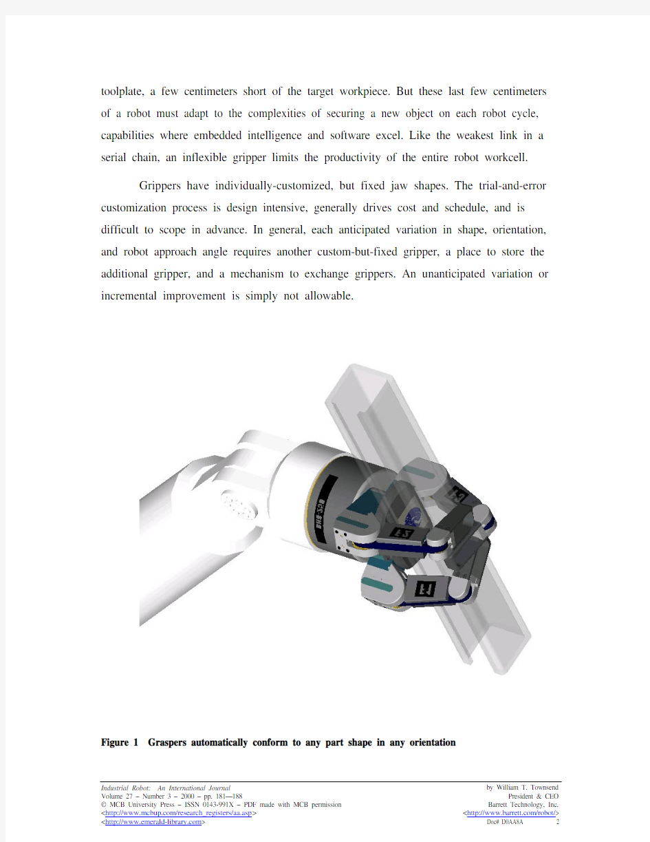
Figure 1 Graspers automatically conform to any part shape in any orientation
By contrast, the mechanical structure of Barrett’s patented grasper, illustrated in Figure 1, is automatically reconfigurable and highly programmable, matching the functionality of virtually any gripper shape or fixture function in less than a second without pausing the workcell throughput to exchange grippers.
For tasks requiring a high degree of flexibility such as handling variably shaped payloads presented in multiple orientations, a grasper is more secure, quicker to install, and more cost effective than an entire bank of custom-machined grippers with tool changers and storage racks.
For uninterrupted operation, just one or two spare graspers can serve as emergency backups for several workcells, whereas one or two spare grippers are required for each gripper variation – potentially dozens per workcell. And, it’s catastrophic if both gripper backups fail in a gripper system, since it may be days before replacements can be identified, custom shaped from scratch, shipped, and physically replaced to bring the affected line back into operation. By contrast, since graspers are physically identical, they are always available in unlimited quantity, with all customization provided instantly in software.
Gripper legacy
Most of today’s robotic part handling and assembling is done with grippers. If surface conditions allow, vacuum suction and electromagnets can also be used, for example in handling automobile windshields and body panels. As part sizes begin to exceed the order of 100gms, a gripper’s jaws are custom shaped to ensure a secure hold. As the durable mainstay of handling and assembly, these tools have changed little since the beginning of robotics three decades ago.
Grippers, which act as simple pincers, have two or three unarticulated fingers, called “jaws”, which either pivot or remain parallel during open/close motions as illustrated in Figure 2. Well organized catalogs are available from manufacturers that guide the integrator or customer in matching various gripper components (except naturally for the custom jaw shape) to the task and part parameters.
Industrial Robot: An International Journal by William T. Townsend
Figure 2 Gripper variations are limited
Payload sizes range from grams for tiny pneumatic grippers to 100+ kilograms for massive hydraulic grippers. The power source is typically pneumatic or hydraulic with simple on/off valve control switching between full-open and full-close states. The jaws typically move 1cm from full-open to full-close. These hands have two or three fingers, called “jaws”. The part of the jaw that contacts the target part is made of a removable and machinably soft steel or aluminum, called a “soft jaw”.
Based on the unique circumstances, an expert tool designer determines the custom shapes to be machined into the rectangular soft-jaw pieces. Once machined to shape, the soft-jaw sets are attached to their respective gripper bodies and tested. This process can take any number of iterations and adjustments until the system works properly. Tool designers repeat the entire process each time a new shape is introduced.
As consumers demand a wider variety of product choices and ever more frequent product introductions, the need for flexible automation has never been greater. However, rather than make grippers more versatile, the robotics industry over the past few years has followed the example of the automatic tool exchange technique used to exchange CNC-
mill cutting tools.
Industrial Robot: An International Journal by William T. Townsend
But applying the tool-changer model to serial-link robots is proving expensive and ineffective. Unlike the standardized off-the-shelf cutting tools used by milling machines, a robot tool designer must customize the shape of every set of gripper jaws — a time-consuming, expensive, and difficult-to-scope task. Although grippers may seem cheap at only US$500 each, the labor-intensive effort to shape the soft jaws may cost several times that. If you multiply that cost times a dozen grippers as in the example above and throw in a toolchanger and tool-storage rack for an additional US$10,000, the real cost of the “few-hundred-dollar” gripper solution balloons to US$20,000 to
US$60,000.
To aggravate matters, unknowns in the customization process confound accurate cost projections. So the customer must commit a purchase order to the initial installation fee on a time and materials basis without guarantee of success or a cost ceiling. While priced at US$30,000, intelligent graspers are not cheap. However, one can “customize” and validate the process in software in a matter of hours at the factory in a single day. If the system does not meet performance targets, then only a day’s labor is wasted. If the system succeeds, then there are not any hidden expenses following the original purchase order.
Beyond cost, the physical weight of tool changer mechanisms, located at the extreme outer end of a serial-link robotic arm, limits the useful payload and dynamic response of the entire system. The additional length of the toolchanger increases the critical distance between the wrist center and payload center, degrading kinematic flexibility, dynamic response, and safety.
Description of the BarrettHand
Flexibility and durability in a compact package
The flexibility of the BarrettHand is based on the articulation of the eight joint axes identified in Figure 3. Only four brushless DC servomotors, shown in Figure 4,
Industrial Robot: An International Journal by William T. Townsend
Industrial Robot: An International Journal by William T. Townsend are needed to control all eight joints, augmented by intelligent mechanical coupling. The resulting 1.18kg grasper is completely self-contained with only an 8mm diameter
umbilical cable supplying DC power and establishing a two-way serial communication link to the main robot controller of the workcell. The grasper’s communications electronics, five microprocessors, sensors, signal processing electronics, electronic
commutation, current amplifiers, and brushless servomotors are all packed neatly inside
the palm body of the grasper.
Figure 3 Eight axes of the BarrettHand
The BarrettHand has three articulated fingers and a palm as illustrated in Figure 5 which act in concert to trap the target object firmly and securely within a grasp consisting
of seven coordinated contact vectors — one from the palm plate and one from each link of each finger.
Figure 4 Motor locations in the BarrettHand
Each of the BarrettHand’s three fingers is independently controlled by one of three servomotors as shown in Figure 6. Except for the spread action of fingers Fl and F2, which is driven by the fourth and last servomotor, the three fingers, Fl, F2, and F3, have inner and outer articulated links with identical mechanical structure.
Each of the three finger motors must drive two joint axes. The torque is channeled to these joints through a patented, TorqueSwitch mechanism (Figure 7), whose function is optimized for maximum grasp security. When a fingertip, not the inner link, makes first contact with an object as illustrated in Figure 8, it simply reaches its required torque, locks both joints, switches off motor currents, and awaits further instructions from the microprocessors inside the hand or a command arriving across the communications link.
Industrial Robot: An International Journal by William T. Townsend
Industrial Robot: An International Journal by William T. Townsend
F1 and F2 Spread around the Palm
F2 F1
F3
Onboard Control
Electronics Package in
Palm Shell TorqueSwitch? Shifts Torque to Appropriate Finger
Joint
Figure 5 Three articulated fingers of the BarrettHand spread and conform to various shapes But when the inner link, as illustrated in Figure 9, makes first contact with an
object for a secure grasp, the TorqueSwitch, reaches a preset threshold torque, locks that joint against the object with a shallow-pitch worm, and redirects all torque to the fingertip to make a second, enclosing contact against the object within milliseconds of the first contact. The sequence of contacts is so rapid that you cannot visualize the process without the aid of high-speed photography. After the grasper releases the object, it sets the TorqueSwitch threshold torque for each finger in anticipation of the next grasp by opening each finger against its mechanical stop with a controlled torque. The higher the opening torque, the higher the subsequent threshold torque. In this way, the grasper can accommodate a wide range of objects from delicate, to compliant, to heavy.
The finger articulations, not available on conventional grippers, allow each digit to conform uniquely and securely to the shape of the object surface with two independent contact points per finger. The position, velocity, acceleration, and even torque can all be
Industrial Robot: An International Journal by William T. Townsend processor controlled over the full range of 17,500 encoder positions. At maximum velocity and acceleration settings, each finger can travel full range in either direction in less than one second. The maximum force that can be actively produced is 2kg, measured at the tip of each finger. Once the grasp is secure, the links automatically lock in place allowing the motor currents to be switched off to conserve power until commanded to readjust or release their grasp.
0o
Figure 6 The inner and outer joints close in a 3-to-4 ratio with respect to the robot toolplate until the inner link strikes an obstacle, activating the TorqueSwitch
While the inner and outer finger-link motions curl anthropomorphically, the
spread motion of Figure 10 is distinctly non-anthropomorphic. The spread motion is closest in function to a primate’s opposable (thumb) finger, but instead of one opposable finger, the BarrettHand has twin, symmetrically opposable fingers centered on parallel joint axes rotating 180 degrees around the entire palm to form a limitless variety of gripper-shapes and fixture functions.
The spread can be controlled to any of [3,000] positions over its full range in either direction within 1/2second. Unlike the mechanically lockable finger-curl motions, the spread motion is fully backdrivable, allowing its servos to provide active stiffness control in addition to control over position, velocity, acceleration, and torque. By allowing the spread motion to be compliant while the fingers close around an object, the grasper seeks maximum grasp stability as the spread accommodates its position, permitting the fingers to find their lowest energy states in the most concave surface features.
Figure 7 The TorqueSwitch mechanism
Electronic and mechanical optimisation
Intelligent, dexterous control is key to the success of any programmable robot, whether it is an arm, automatically guided vehicle, or dexterous hand. While robotic intelligence is usually associated with processor-driven motor control, many biological systems, including human hands, integrate some degree of specialized reflex control independent of explicit motor-control signals from the brain. In fact, the BarrettHand combines reflexive mechanical intelligence and programmable microprocessor intelligence for a high degree of practical dexterity in real-world applications.
Industrial Robot: An International Journal by William T. Townsend
Industrial Robot: An International Journal by William T. Townsend Figure 8 TorqueSwitch behavior for fingertip gripping
By strict mathematical definition, dexterity requires independent, intelligent
motor control over each and every articulated joint axis. For a robot to be dexterous, at least n independent servomotors, and sometimes as many as n + 1 or 2n , are required to drive n joint axes. Unfortunately, servomotors constitute the bulkiest, costliest, and most complex components of any dexterous robotic hand. So, while the strict definition of dexterity may be mathematically elegant, it leads to impractical designs for any real
application.
Gear Stays against Compression
Spring
Second Link Touches
Object Finger Fully Open
Gear Compressed Against Spring 3
4
Industrial Robot: An International Journal by William T. Townsend Figure 9 TorqueSwitch behavior for secure, finger-enclosed grasping
According to the definition, neither your hand nor the BarrettHand is dexterous. Naturally, their superior versatility challenges the definition itself. If the BarrettHand followed the strict definition for dexterity, it would require between eight and 16 motors,
making it far too bulky, complex, and unreliable for any practical application outside the Inner Link Contacts Object
Torque increases, and Gear breaks
away from Compression Spring
Outer Link Contacts
Object, and Finger Stops Gear Stops Traveling along Thread
Finger Begins to
Open Gear Travels Back Toward Spring
Finger Fully Open
with Gear
“tightened” against
Compression Spring
Industrial Robot: An International Journal by William T. Townsend mathematical analysis of hand dexterity. But, by exploiting four intelligent, joint-
coupling mechanisms, the almost-dexterous BarrettHand requires only four servomotors.
F3
Figure 10 Spread motion of outer two fingers, F1 and F2
In some instances reflex control is even better than deliberate control. Two
examples based on your own body illustrate this point. Suppose your hand accidentally touches a dangerously hot surface. It begins retracting itself instantly, relying on local reflex to override any ongoing cognitive commands. Without this reflex behavior, your hand would burn while waiting for the sensations of pain to travel from your hand to your brain via relatively slow nerve fibers and then for your brain, through the same slow nerve fibers, to command your arm, wrist, and finger muscles to retract.
As the second example, try to move the outer joint of your index finger without moving the adjacent joint on the same finger. If you are like most people, you cannot move these joints independently because the design of your hand is optimized for grasping. Your muscles and tendons are as streamlined and lightweight as possible without forfeiting functionality.
The design of the BarrettHand recognizes that intelligent control of functional dexterity requires the integration of microprocessor and mechanical intelligence.
Control electronics
Inside its compact palm, the BarrettHand contains its central supervisory microprocessor that coordinates four dedicated motion-control microprocessors and controls I/O via the RS232 line. The control electronics, partially visible in Figure 4 are built on a parallel 70-pin backplane bus. Associated with each motion-control microprocessor are the related sensor electronics, motor commutation electronics, and motor-power current-amplifier electronics for that finger or spread action.
The supervisory microprocessor directs I/O communication via a high-speed, industry-standard RS232 serial communications link to the workcell PC or controller. RS232 allows compatibility with any robot controller while limiting umbilical cable diameter for all power and communications to only 8mm. The openly published grasper communications language (GSL)
While the robotic arm requires high control bandwidth during the entire cycle, the grasper has plenty of time to receive a large amount of setup information as it approaches its target. Then, with precision timing, the workcell controller releases a “trigger” command, such as the ASCII character “C” for close, that begins grasp execution within a couple milliseconds.
Grasper control language (GCL)
The grasper can communicate and accept commands from any robot-workcell controller, PC, Mac, UNIX box, or even a Palmpilot via standard ASCII RS232-C serial communication — the common denominator of communications protocols. Though robust, RS232 has a reputation for slow bandwidth compared to USB or FireWire standards, but its simplicity leads to small latencies for short bursts of data. By
Industrial Robot: An International Journal by William T. Townsend
streamlining the GCL, we have achieved time of flight to execute and acknowledge a command (from the workcell controller to the grasper and then back again to the workcell controller) of the order of milliseconds. The initial effort to develop a highly optimized grasper language based on such a standard protocol means that the GCL is upwardly compliant with any future industry-standard protocol.
The grasper has two control modes: supervisory and realtime. Supervisory is the normal mode used to control the grasper. It is made up of a simple command structure, designed for optimal performance and minimized learning curve.
Supervisory mode has the following grammatical structure:
Object (prefix) — Verb (command) — Subject (parameters) — Qualifiers (values)
The prefix refers to motors 1 through 4 with the ASCII values for 1, 2, 3, and 4 corresponding to the fingers Fl, F2, F3, and the spread motion. Any number of prefixes may be used in any order. If the prefix is omitted, then the grasper applies the command to all available axes.
As an example, the ASCII character “C” represents the command which drives the associated motor(s) at its individual default (or user defined) velocity and acceleration profile(s) until the motor(s) stops for the default (or user defined) number of milliseconds. As each motor reaches this state its position is locked mechanically in place.
?1C closes finger Fl.
?2C closes finger F2.
?12C closes fingers Fl and F2.
? C is equivalent to 1234C and closes all three fingers and the spread motion.
We also have defined “S” (derived from “spread”) as a shortcut for “4” and “G” (from “grasp”) as a short cut for “123”, so that:
?GC is equivalent to 123C
?SC is equivalent to 4C
Industrial Robot: An International Journal by William T. Townsend
There are similar commands for opening fingers, moving any combination of the four axes to an array of positions, incremental opening and closing by default or user-defined distances, reading and setting user-defined parameter values, and reading the (optional) strain gages on the three fingers. The latest version of the BH8-250 firmware has 21 commands and 28 parameter settings, giving it almost unlimited flexibility.
The realtime mode is reserved for advanced uses such as realtime teleoperation control and is frequently accessed through Barrett’s user-friendly GUI for PCs running Windows95/98/NT. In realtime mode, the user specifies a tailored packet-structure in supervisory mode. Barrett’s PC software gives the user a histogram of 20 successive time-of-flight tests so that the user can refine the packet structure by quantitatively balancing information content with latency.
The GUI accelerates the prototyping of tasks and includes a pictorial of the grasper with sliders for position and rate control. The GUI also has a novel “Generate
C++ Code” button which enables anyone to save and later recall successful algorithms without any knowledge of C or C++ programming. But, with C++ programming familiarity, you can also edit the code as desired.
Once realtime mode is initiated, packets are exchanged in full duplex until an ASCII control character is issued to break out of realtime mode and return to supervisory mode. The system has proven effective and robust in a variety of customer applications.
Conclusion
Although the BarrettHand BH8-250 was only introduced commercially in 1999, 30 units have been put into service around the globe at a price of US$30,000 each. The largest concentration of graspers is among automotive manufacturers and suppliers in Japan, including Honda, Yamaha Motorcycles, and NGK (ceramic substrates for catalytic converters). At this time, these manufacturers are only beginning to explore the capabilities of this versatile device, while some customers, such as Fanuc Robotics and the US and Japanese space programs have become repeat customers.
Industrial Robot: An International Journal by William T. Townsend
缸体机械加工工艺设计 发动机缸体是发动机零件中结构较为复杂的箱体零件,其精度要求高,加工工艺复杂,并且加工加工质量的好坏直接影响发动机整个机构的性能,因此,它成为各个发动机生产厂家所关注的重点零件之一。 1.发动机缸体的工艺特点 缸体为一整体铸造结构,其上部有4个缸套安装孔;缸体的水平隔板将缸体分成上下两部分;缸体的前端面从到后排列有三个同轴线的凸轮轴安装孔和惰轮轴孔。 缸体的工艺特点是:结构、形状复杂;加工的平面和孔比较多;壁厚不均,刚度低;加工精度要求高,属于典型的箱体类加工零件。缸体的主要加工表面有顶面、主轴承侧面、缸孔、主轴承孔及凸轮轴孔等,它们的加工精度将直接影响发动机的装配精度和工作性能,主要依靠设备进度、工夹具的可靠性和加工工艺的合理性来保证。 2. 发动机缸体工艺方案设计原则和依据 设计工艺方案应在保证产品质量的同时,充分考虑生产周期、成本和环境保护;根据本企业能力,积极采用国内外先进的工艺技术和装备,不断提高企业工艺水平。发动机缸体机械加工工艺设计应遵循以下基本原则: (1)加工设备选型原则加工设备选型采用刚柔结合的原则,加工设备以卧式加工中心为主,少量采用立式加工中心,关键工序—曲轴孔、缸孔、平衡轴孔加工采用高精度高速卧式加工中心,非关键工序—上下前后四个平面的粗铣采用高效并有一定调整范围的专用机床加工; (2)集中工序原则关键工序—曲轴孔、缸孔、平衡轴孔的精加工缸盖结合面的精铣,采用在集中在一道工序一次装夹完成全部加工内容方案,以确保产品精度满足缸体关键品质的工艺性能和有关技术要求。 根据汽车发动机缸体的工艺特点和生产任务要求,发动机缸体机械加工自动生产线由卧式加工中心CWK500和CWK500D加工中心、专用铣/镗床、立式加工中心matec-30L等设备组成。 (1)顶底面及瓦盖止口面粗铣组合机床本机床为双面卧式专用铣床,采用移动工作台带动工件,机床采用进口西门子S7-200PLC系统控制,机床设独立电控柜,切削过程自动化完成,有自动和调整两种状态; (2)高速卧式加工中心CWK500 该加工中心可实现最大流量的湿加工,但由于设备自动排屑处理系统是通过位于托盘下的内置宽式排屑器而完成,该加工中心可以进行干加工;机床主轴转速6000r/min,快速进给速度38m/min; (3)前后端面粗铣组合机床机床采用液压传动;控制系统采用进口西门子S7-200PLC系统控制,机床具有一定的柔性; (4)采用机床TXK1500 本机床有立式加工中心改造而成形,具备立式加工中心的特点及性能,该机床具有高精度、高强度、高耐磨度、高稳定性、高配置等优点; (5)高速立式加工中心matec-30L 该加工中心主轴最高转速9000 r/min。控制系统采用西门子公司SINUMERIK840D控制系统 (6)高速卧式加工中心CWK500D 主轴最高转速15000 r/min。 3. 发动机缸体机械加工工艺设计的主要内容 发动机缸体结构复杂,精度要求高,尺寸较大,是薄壁零件,有若干精度要
机械设计 摘要:机器是由机械装置和其它组件组成的。它是一种用来转换或传递能量的装置,例如:发动机、涡轮机、车辆、起重机、印刷机、洗衣机、照相机和摄影机等。许多原则和设计方法不但适用于机器的设计,也适用于非机器的设计。术语中的“机械装置设计”的含义要比“机械设计”的含义更为广泛一些,机械装置设计包括机械设计。在分析运动及设计结构时,要把产品外型以及以后的保养也要考虑在机械设计中。在机械工程领域中,以及其它工程领域中,所有这些都需要机械设备,比如:开关、凸轮、阀门、船舶以及搅拌机等。 关键词:设计流程设计规则机械设计 设计流程 设计开始之前就要想到机器的实际性,现存的机器需要在耐用性、效率、重量、速度,或者成本上得到改善。新的机器必需具有以前机器所能执行的功能。 在设计的初始阶段,应该允许设计人员充分发挥创造性,不要受到任何约束。即使产生了许多不切实际的想法,也会在设计的早期,即在绘制图纸之前被改正掉。只有这样,才不致于阻断创新的思路。通常,还要提出几套设计方案,然后加以比较。很有可能在这个计划最后决定中,使用了某些不在计划之内的一些设想。 一般的当外型特点和组件部分的尺寸特点分析得透彻时,就可以全面的设计和分析。接着还要客观的分析机器性能的优越性,以及它的安全、重量、耐用性,并且竞争力的成本也要考虑在分析结果之内。每一个至关重要的部分要优化它的比例和尺寸,同时也要保持与其它组成部分相协调。 也要选择原材料和处理原材料的方法。通过力学原理来分析和实现这些重要的特性,如那些静态反应的能量和摩擦力的最佳利用,像动力惯性、加速动力和能量;包括弹性材料的强度、应力和刚度等材料的物理特性,以及流体润滑和驱动器的流体力学。设计的过程是重复和合作的过程,无论是正式或非正式的进行,对设计者来说每个阶段都很重要。 最后,以图样为设计的标准,并建立将来的模型。如果它的测试是符合事先要
前言 在目前激烈的市场竞争中,产品投入市场的迟早往往是成败的关键。模具是高质量、高效率的产品生产工具,模具开发周期占整个产品开发周期的主要部分。因此客户对模具开发周期要求越来越短,不少客户把模具的交货期放在第一位置,然后才是质量和价格。因此,如何在保证质量、控制成本的前提下加工模具是值得认真考虑的问题。模具加工工艺是一项先进的制造工艺,已成为重要发展方向,在航空航天、汽车、机械等各行业得到越来越广泛的应用。模具加工技术,可以提高制造业的综合效益和竞争力。研究和建立模具工艺数据库,为生产企业提供迫切需要的高速切削加工数据,对推广高速切削加工技术具有非常重要的意义。本文的主要目标就是构建一个冲压模具工艺过程,将模具制造企业在实际生产中结合刀具、工件、机床与企业自身的实际情况积累得高速切削加工实例、工艺参数和经验等数据有选择地存储到高速切削数据库中,不但可以节省大量的人力、物力、财力,而且可以指导高速加工生产实践,达到提高加工效率,降低刀具费用,获得更高的经济效益。 1.冲压的概念、特点及应用 冲压是利用安装在冲压设备(主要是压力机)上的模具对材料施加压力,使其产生分离或塑性变形,从而获得所需零件(俗称冲压或冲压件)的一种压力加工方法。冲压通常是在常温下对材料进行冷变形加工,且主要采用板料来加工成所需零件,所以也叫冷冲压或板料冲压。冲压是材料压力加工或塑性加工的主要方法之一,隶属于材料成型工程术。 冲压所使用的模具称为冲压模具,简称冲模。冲模是将材料(金属或非金属)批量加工成所需冲件的专用工具。冲模在冲压中至关重要,没有符合要求的冲模,批量冲压生产就难以进行;没有先进的冲模,先进的冲压工艺就无法实现。冲压工艺与模具、冲压设备和冲压材料构成冲压加工的三要素,只有它们相互结合才能得出冲压件。 与机械加工及塑性加工的其它方法相比,冲压加工无论在技术方面还是经济方面都具有许多独特的优点,主要表现如下; (1) 冲压加工的生产效率高,且操作方便,易于实现机械化与自动化。这是
机械外文文献翻译 Overall position of Agricultural Mechanization in Turkey Agricultural equipment and machinery are the indispensable part of agricultural activities. If these instruments, which are used in various stages of production, are not used properly, there may be some problems. So, how can we use them properly ? As the proverb goes, “It is the want of care that makes the field bare”. They return the money and efforts invested in them if they are maintained well. Ploughs, which were being used in our country up until recently, resemble those ploughs of the various tribes that lived in Anatolia long time ago. It is because one society gets use of societies that lived before. Some of the black ploughs that were being used up until recently resemble the ploughs that had been used in the ancient Rome. The first agricultural school was established in the Ottoman Empire in 1846. The first domestic heavy ploughs was manufactured i n Izmir 90 years ago, and tractor was introduced 80 years ago. However, it was only the foundation of the Republic that the tractor began to be used in agricultural activities. Agricultural mobilization began with modern agricultural practices in the Atatürk Forest Farm, which was founded by the Great Atatürk. Use of modern agricultura l equipment was encouraged,
机械类毕业设计外文翻译
外文原文 Options for micro-holemaking As in the macroscale-machining world, holemaking is one of the most— if not the most—frequently performed operations for micromachining. Many options exist for how those holes are created. Each has its advantages and limitations, depending on the required hole diameter and depth, workpiece material and equipment requirements. This article covers holemaking with through-coolant drills and those without coolant holes, plunge milling, microdrilling using sinker EDMs and laser drilling. Helpful Holes Getting coolant to the drill tip while the tool is cutting helps reduce the amount of heat at the tool/workpiece interface and evacuate chips regardless of hole diameter. But through-coolant capability is especially helpful when deep-hole microdrilling because the tools are delicate and prone to failure when experiencing recutting of chips, chip packing and too much exposure to carbide’s worst enemy—heat. When applying flood coolant, the drill itself blocks access to the cutting action. “Somewhere about 3 to 5 diam eters deep, the coolant has trouble getting down to the tip,” said Jeff Davis, vice president of engineering for Harvey Tool Co., Rowley, Mass. “It becomes wise to use a coolant-fed drill at that point.” In addition, flood coolant can cause more harm than good when microholemaking. “The pressure from the flood coolant can sometimes snap fragile drills as they enter the part,” Davis said. The toolmaker offers a line of through-coolant drills with diameters from 0.039" to 0.125" that are able to produce holes up to 12 diameters deep, as well as microdrills without coolant holes from 0.002" to 0.020". Having through-coolant capacity isn’t enough, though. Coolant needs to flow at a rate that enables it to clear the chips out of the hole. Davis recommends, at a minimum, 600 to 800 psi of coolant pressure. “It works much better if you have higher pressure than that,” he added. To prevent those tiny coolant holes from becoming clogged with debris, Davis also recommends a 5μm or finer coolant filter. Another recommendation is to machine a pilot, or guide, hole to prevent the tool from wandering on top of the workpiece and aid in producing a straight hole. When applying a pilot drill, it’s important to select one with an included angle on its point that’s equal t o or larger than the included angle on the through-coolant drill that follows.
附:外文翻译 外文原文: Fundamentals of Mechanical Design Mechanical design means the design of things and systems of a mechanical nature—machines, products, structures, devices, and instruments. For the most part mechanical design utilizes mathematics, the materials sciences, and the engineering-mechanics sciences. The total design process is of interest to us. How does it begin? Does the engineer simply sit down at his desk with a blank sheet of paper? And, as he jots down some ideas, what happens next? What factors influence or control the decisions which have to be made? Finally, then, how does this design process end? Sometimes, but not always, design begins when an engineer recognizes a need and decides to do something about it. Recognition of the need and phrasing it in so many words often constitute a highly creative act because the need may be only a vague discontent, a feeling of uneasiness, of a sensing that something is not right. The need is usually not evident at all. For example, the need to do something about a food-packaging machine may be indicated by the noise level, by the variations in package weight, and by slight but perceptible variations in the quality of the packaging or wrap. There is a distinct difference between the statement of the need and the identification of the problem. Which follows this statement? The problem is more specific. If the need is for cleaner air, the problem might be that of reducing the dust discharge from power-plant stacks, or reducing the quantity of irritants from automotive exhausts. Definition of the problem must include all the specifications for the thing that is to be designed. The specifications are the input and output quantities, the characteristics of the space the thing must occupy and all the limitations on t hese quantities. We can regard the thing to be designed as something in a black box. In this case we must specify the inputs and outputs of the box together with their characteristics and limitations. The specifications define the cost, the number to be manufactured, the expected life, the range, the operating temperature, and the reliability. There are many implied specifications which result either from the designer's particular environment or from the nature of the problem itself. The manufacturing processes which are available, together with the facilities of a certain plant, constitute restrictions on a designer's freedom, and hence are a part of the implied specifications. A small plant, for instance, may not own cold-working machinery. Knowing this, the designer selects other metal-processing methods which can be performed in the plant. The labor skills available and the competitive situation also constitute implied specifications. After the problem has been defined and a set of written and implied specifications has been obtained, the next step in design is the synthesis of an optimum solution. Now synthesis cannot take place without both analysis and optimization because the system under design must be analyzed to determine whether the performance complies with the specifications. The design is an iterative process in which we proceed through several steps, evaluate the results, and then return to an earlier phase of the procedure. Thus we may synthesize several components of a system, analyze and optimize them, and return to synthesis to see what effect this has on the remaining parts of the system. Both analysis and optimization require that we construct or devise abstract models of the system which will admit some form of mathematical analysis. We call these models
外文翻译 英文原文 Belt Conveying Systems Development of driving system Among the methods of material conveying employed,belt conveyors play a very important part in the reliable carrying of material over long distances at competitive cost.Conveyor systems have become larger and more complex and drive systems have also been going through a process of evolution and will continue to do so.Nowadays,bigger belts require more power and have brought the need for larger individual drives as well as multiple drives such as 3 drives of 750 kW for one belt(this is the case for the conveyor drives in Chengzhuang Mine).The ability to control drive acceleration torque is critical to belt conveyors’performance.An efficient drive system should be able to provide smooth,soft starts while maintaining belt tensions within the specified safe limits.For load sharing on multiple drives.torque and speed control are also important considerations in the drive system’s design. Due to the advances in conveyor drive control technology,at present many more reliable.Cost-effective and performance-driven conveyor drive systems covering a wide range of power are available for customers’ choices[1]. 1 Analysis on conveyor drive technologies 1.1 Direct drives Full-voltage starters.With a full-voltage starter design,the conveyor head shaft is direct-coupled to the motor through the gear drive.Direct full-voltage starters are adequate for relatively low-power, simple-profile conveyors.With direct fu11-voltage starters.no control is provided for various conveyor loads and.depending on the ratio between fu11-and no-1oad power requirements,empty starting times can be three or four times faster than full load.The maintenance-free starting system is simple,low-cost and very reliable.However, they cannot control starting torque and maximum stall torque;therefore.they are
附录一英文科技文献翻译 英文原文: Experimental investigation of laser surface textured parallel thrust bearings Performance enhancements by laser surface texturing (LST) of parallel-thrust bearings is experimentally investigated. Test results are compared with a theoretical model and good correlation is found over the relevant operating conditions. A compari- son of the performance of unidirectional and bi-directional partial-LST bearings with that of a baseline, untextured bearing is presented showing the bene?ts of LST in terms of increased clearance and reduced friction. KEY WORDS: ?uid ?lm bearings, slider bearings, surface texturing 1. Introduction The classical theory of hydrodynamic lubrication yields linear (Couette) velocity distribution with zero pressure gradients between smooth parallel surfaces under steady-state sliding. This results in an unstable hydrodynamic ?lm that would collapse under any external force acting normal to the surfaces. However, experience shows that stable lubricating ?lms can develop between parallel sliding surfaces, generally because of some mechanism that relaxes one or more of the assumptions of the classical theory. A stable ?uid ?lm with su?cient load-carrying capacity in parallel sliding surfaces can be obtained, for example, with macro or micro surface structure of di?erent types. These include waviness [1] and protruding microasperities [2–4]. A good literature review on the subject can be found in Ref. [5]. More recently, laser surface texturing (LST) [6–8], as well as inlet roughening by longitudinal or transverse grooves [9] were suggested to provide load capacity in parallel sliding. The inlet roughness concept of Tonder [9] is based on ??e?ective clearance‘‘ reduction in the sliding direction and in this respect it is identical to the par- tial-LST concept described in ref. [10] for generating hydrostatic e?ect in high-pressure mechanical seals. Very recently Wang et al. [11] demonstrated experimentally a doubling of the load-carrying capacity for the surface- texture design by reactive ion etching of SiC
Manufacturing Engineering and Technology—Machining Serope kalpakjian;Steven R.Schmid 机械工业出版社2004年3月第1版 20.9 MACHINABILITY The machinability of a material usually defined in terms of four factors: 1、Surface finish and integrity of the machined part; 2、Tool life obtained; 3、Force and power requirements; 4、Chip control. Thus, good machinability good surface finish and integrity, long tool life, and low force And power requirements. As for chip control, long and thin (stringy) cured chips, if not broken up, can severely interfere with the cutting operation by becoming entangled in the cutting zone. Because of the complex nature of cutting operations, it is difficult to establish relationships that quantitatively define the machinability of a material. In manufacturing plants, tool life and surface roughness are generally considered to be the most important factors in machinability. Although not used much any more, approximate machinability ratings are available in the example below. 20.9.1 Machinability Of Steels Because steels are among the most important engineering materials (as noted in Chapter 5), their machinability has been studied extensively. The machinability of steels has been mainly improved by adding lead and sulfur to obtain so-called free-machining steels. Resulfurized and Rephosphorized steels. Sulfur in steels forms manganese sulfide inclusions (second-phase particles), which act as stress raisers in the primary shear zone. As a result, the chips produced break up easily and are small; this improves machinability. The size, shape, distribution, and concentration of these inclusions significantly influence machinability. Elements such as tellurium and selenium, which are both chemically similar to sulfur, act as inclusion modifiers in
1 Introduction The key task for the automobile industry and its suppliers in future lies in speedily developing and implementing ecologically sound and economically justifiable mobility systems. Light metals such as aluminum and magnesium along with glass and carbon fiber reinforced materials, ceramics and composites have opened up the potential for considerable weight reduction and for "green" vehicle concepts which can be realized economically. Aluminum in particular can provide the impetus for new designs for the next millennium. Decades ago, the use of aluminum in auto construction was seen as an "experiment"; Today it is a vital factor in reducing weight and thus lowering fuel consumption. The average passenger car today contains 60 to 70 kg of aluminum, and current developments point to a doubling of this amount in the next few years. Motor vehicles both now and in future must meet requirements for: greater performance, greater safety, comfort, low pollution. Lightweight construction is not just about reducing weight; it is a question of -striking the right balance between reduced weight and structural efficiency. In vehicle construction this normally means making the best use of the generally very tight space available for individual components so as to allow weight to be minimized while still meeting all stiffness, strength, natural frequency or acoustical requirements. To achieve this, stresses must be distributed throughout the structure as evenly as possible. Modern numerical analysis methods such as FEA allow a very detailed analysis of system behavior, provide cost-efficient support for the complex process of optimization and thus make a huge contribution to advances in lightweight construction. Packaging, safety considerations, reproducibility and price place restrictions on the degree of weight reduction achievable. The broad range of expertise available to Krupp Presta AG allows the company to analyze customer specifications for steering systems and provide appropriate solutions. 2 Requirements to be met by steering systems The steering is an important part of the feel of a car. The steering system should make driving an enjoyable experience with no unpleasant vibration from the road surface while guaranteeing the required hand- sing. It is also important that high safety requirements be met, both under normal conditions and in crash situations. The key criteria for the steering system are thus as follows:rolling friction, torsional stiffness /strength, Damping, temperature, corrosion, durability / fatigue, weight. Crash kinematics and energy absorption steering column requirements:natural frequency / stiffness, mass, damping, space, strength (crash, misuse), ergonomics, handling, acoustics, crash kinematics and energy absorption. Other basic conditions:interfaces with adjacent components, installation, joining techniques, price. 3 Materials material light weighting can be achieved by using either stronger or lighter material. When stiffness or natural frequency are Important sizing criteria, low density materials with a high modulus of elasticity by quired. Non-exotic materials must be selected which are readily recyclable, low in price and display good durability.Further requirements are set by the manufacturing and joining processes. Steel, aluminum, magnesium and a variety of plastics are the materials of choice for steering systems.