Decoupling Scheme of Tracking Loop of Seeker Based on Disturbance Compensation
XXXXXX1, XXXXXXX 2, XXXXXXXX 2
(1.XXXXXXXXXXXXXXXXXXXXXXX;
2XXXXXXXXXXXXXXXXXXXXXX)
Abstract:To get line-of-sight rate of high-accuracy for guidance, finishing aerial attack and intercept when the missile is controlled by lateral jets which will cause high frequency disturbance to missile attitude, a new decoupling scheme is proposed based on disturbance compensation in this paper. Decoupling-ability, tracking performance and noise rejection ability are analyzed and compared with the two existing method. Simulation and analysis show the effectiveness of the scheme proposed.
Keywords:Guidance; Lateral jets; Line-of-sight rate; Decoupling; high-accuracy; compensation
Introduction
Contemporary military strategy has developed from underlining quantity advantage to technical quality advantage. Precision guided weapon is the main way of physical killing, and perform an important role in informatization local wars [1]-[3]. Precision guidance technology is critical for the precision guided weapon, so it is always studied by experts and researchers from many countries.
Seeker is a kind of measuring component in controlling loop of homing guidance [4]. It is required to output information of line-of-sight (LOS for short) rate for guidance. So the precision of its output, LOS rate, affects controlling precision of terminal guidance directly. While a seeker is in the state of tracking, the antenna on it should track the direction of the target. A seeker works on a moving missile. So the disturbance caused by the missile body movement must be separated from the antenna to keep it stable in the inertial space [4]-[5]. The traditional design idea is to use a stabilization loop to attenuate the LOS output caused by body disturbance. We call it traditional multi-loop (TML for short) scheme [4]-[6]. There are also some schemes based on TML scheme, for example, decoupling-loop scheme which changes the position of the loop’s output to improve the decoupling-ability and at the same time have some advantages on design of guidance [7]-[8]. However, it is difficult to decouple disturbance by using the schemes mentioned above. Line-of-sight reconstruction(LOSR for short) scheme, by F.William and Paul Zarchan, can decouple completely in ideal conditions in which the transfer function of the receiver and the gyro are both equal to 1 [9]. In fact, these two conditions can’t be satisfied in the presence of high-frequency disturbance. In modern war, missiles need larger maneuverability to intercept aerial target with high speed and large maneuverability. New types of physical actuators bring high-frequency characteristics to missile movement. The high-frequency characteristics require more effective decoupling method for the seeker. Considering weight and cost, the open-loop gain can’t be too high while the time constant of the servo motor and the gyro fixed on the antenna can’t be too small. These restrictions limit further enhance of decoupling-ability. The existing schemes can only reject disturbance in low frequency segment and very high frequency segment effectively. In the frequency segment which missile moving disturbance can actually reach, decoupling-ability of seekers becomes weaker when missile movement frequency turns high.
In fact, missile disturbance is able to be measured. Gyro fixed on missile for guidance and attitude
controlling can measure missile rate information of three channels (pitch, yaw and roll) in real-time. But none of the existing schemes make use of this measurable information effectively. In this paper, a new scheme is brought up to strengthen decoupling-ability of seeker after making full use of the measurable missile rate.
This paper is organized as follows:
Section II gives the problem formulation of seeker ’s decoupling and tracking. In section III, a new decoupling scheme, disturbance compensation (DC for short) scheme is proposed and analyzed in detail. After that, simulation and analysis about performances including tracking ability and noise rejection, especially decoupling-ability is done to compare DC scheme and two existing scheme (TML and LOS scheme) in section IV. Finally, we conclude this paper with several conclusions.
1. Problem Formulation
1.1Basic Control Structure of Seeker
Seekers are used to tracking a moving target by orienting its antenna so as to always point towards the target. A seeker makes use of a receiver, a angle gyro fixed on its antenna and a servo system (always a motor with controller) to work. In absence of noise, its
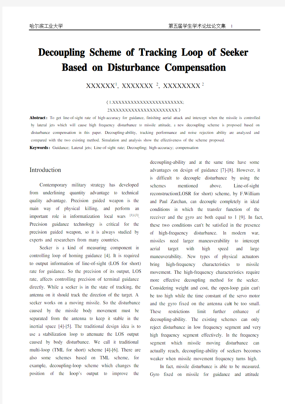
basic control structure is shown in Fig. 1.
Disturbance
Turning rate of antenna
pointing
Fig. 1 Basic Control Structure of Seeker
Its working principle is stated by the following: The tracking-loop of seeker is formed by a receiver and a stabilization-loop which is an inner loop of the tracking-loop. Receiver is a kind of sensor
for angular measurement whose output voltage is in proportion to its input error angular. When antenna is not pointing to the target exactly, the receiver outputs a voltage in proportion to the pointing error. To make sure that the antenna pointing is stable in the inertial coordinates, transport motion caused by the body must be separated from the antenna because the seeker works on a moving missile [4]. For this reason, stabilization- loop is established in a way of feedback using servo system and angular rate gyro fixed on the antenna, and the gyro is installed in the feedback channel. When missile movement transfers to the antenna, feedback signal tapped from the gyro (voltage in proportion to turning rate of antenna pointing in relative to inertial space) drives the servomechanism to rotate in the opposite direction, annulling the effect of body rate disturbances in the synthesized antenna pointing rate.
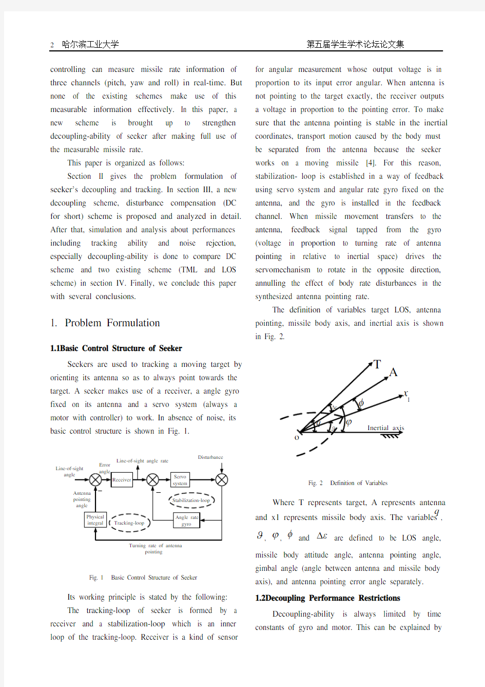
The definition of variables target LOS, antenna pointing, missile body axis, and inertial axis is shown in Fig. 2.
1
Fig. 2 Definition of V ariables
Where T represents target, A represents antenna and x1 represents missile body axis. The variables q ,
?, ?, φ and ε? are defined to be LOS angle,
missile body attitude angle, antenna pointing angle, gimbal angle (angle between antenna and missile body axis), and antenna pointing error angle separately. 1.2Decoupling Performance Restrictions
Decoupling-ability is always limited by time constants of gyro and motor. This can be explained by
the following analysis:
Ignore controller of the motor for convenience, and isolate stabilization-loop of seeker from the whole seeker ’s tracking system, we get Fig. 3.
Where
m G is transfer function of motor and
g
G is transfer function of angle rate gyro fixed on
antenna. ?,
? and φ is differential of ?, ? and
φ respectively.
+
φ
Fig. 3 Angle Stabilization-loop
From Fig. 3, we can see that the output from ?
to ?
can reflect seeker ’s decoupling-ability. The
smaller the modulus of
/φ? is, the better
decoupling-ability the system has. m G and g G are
defined as follows:
1
m
m m K G T s =
+ (1)
22
21
g
g g g g K G T s T s ξ=
++ (2)
Where m K is motor gain, m T is time constant
of motor.
g K ,
g
T and
g
ξ is gain, time constant
and damping ratio of gyro on antenna.
So, we have
1
1m g
G G φ?=
+ (3)
In order to get better decoupling, we always design
1m g G G >>. Approximately, we have
221(1)(21)
m g
m g g m g
G G T s T s T s K K φ?ξ≈
+++=
(4)
According to (4), decoupling performance bode diagram is shown in Fig. 4.
From
Fig.
4,
it
can
be
seen
that
stabilization-loop ’s rejection of missile disturbance is
strong in low
frequency and becomes weaker in
medium and high frequency. To obtain better decoupling-ability, gyro time constant
g
T and motor
time constant
m T should be reduced, and gyro gain
g
K and motor gain
m K should be increased. But
the degree that these constants can reduce or increase is limited by cost, weight, and physical achievability. Therefore, decoupling bandwidth can ’t be designed too wide.
Fig. 4 Decoupling Performance Bode Diagram
2. Decoupling Scheme of Seeker Based on Disturbance Compensation
2.1DC Scheme
To overcome that decoupling-ability turns weak when frequency turns to medium and high frequency segment, a DC scheme is presented in this paper, in which the disturbance is measured by gyro on missile
body and compensated to stabilization-loop through certain link. Block diagram of DC scheme is shown in
Fig. 5.
+
φ
Fig. 5 Disturbance Compensation Decoupling Scheme
Where ?q is estimation of LOS angle rate, f G is transfer function of filter, r G is transfer function of receiver, c G is transfer function of power
amplifier, a G is controller of motor, '
g G is transfer
function of gyro in missile body and b G is
rectification set designed according to system parameters and requirement.
b G and '
g
G make up
of the disturbance compensation channel. 2.2Decoupling Principle of DC Scheme
Theoretically, DC scheme can decouple absolutely
without
stabilization-loop.
But
full-compensation can ’t be achieved in actual situation. Therefore ,the stabilization-loop is still kept.
By
Mason
formula,
assumption
of
full-compensation is '
10g b a m G G G G -=
(5)
That is '
1
b g a m
G G G G =
(6)
Where
121
1
a a a T s G T s +=
+
(7)
''22''
1
21
g g g g G T s T s ξ=
++ (8)
Where
1a T and 2a T are time constant of motor
controller a G , 'g T is time constant of gyro in
missile body, and
'g
ξ is damping ratio of gyro in
missile body.
Because the numerator of b G is three orders higher than the denominator,
b G is only proper
theoretically, but can ’t be achieved. Therefore, only partial-compensation is considered. In fact, bandwidth of gyro
'
g
G fixed on missile body is wider than that
fixed on antenna. Time constant of 'g
G can be made
small. In this case, dynamic process of this gyro can be ignored in bandwidth of stabilization-loop to make partial-compensation. That is '
g 1
G ≈. Then
b G can
be easily designed to be
'2111
1(1)(1)(1)(1)
b g a m
a m
a m m a G G G G G G T s T s K T s T s =
≈++=
++
(9)
Where
1T is a small time constant for
realization.
The smaller the time constants '
g T and
1T are,
the better decoupling-ability DC scheme has.
Therefore, when designing b G , time constants '
g T
and
1T should be chosen as small as possible.
3. Performance Analysis, Simulation
and Comparison
3.1TML and LOSR Scheme
Control structure of TML [8] scheme is shown in Fig. 6.
?
+
φ
Fig. 6 Traditional Multi-loop Scheme
Where 1L and 2L are stabilization-loop and tracking-loop respectively. 1L is used to separate the
missile body rate output in order to stable the antenna in inertial space, and 2L is designed to finish the tracking function. TML scheme is based on the control structure in Fig. 1, strengthening its decoupling-ability by designing proper controller and rectification device.
LOSR scheme is proposed by F.William Nesline and Paul Zarchan first [9], shown in Fig. 7.
Where *
ε? is voltage corresponding to error
angle output from receiver, *
?q is the reconstructed LOS angle, d G is differential and filter link and *?q
is output of LOSR (LOS rate).
r G +
φ
c
G q
? *
ε
?noise
Fig. 7 Line-of-Sight Reconstruction Scheme
The design idea of LOSR is: Gyro fixed on antenna measures antenna ’s angle rate with respect to inertial space. The output of the gyro is integrated to
give antenna pointing angle φ. Adding it to error angle *
ε?, which is output of receiver, LOS angle
*?q
is obtained, shown in Fig. 2 and Fig. 7. Through a differential and filter link
d G , th
e estimation o
f LOS
rate, *?q is obtained.
3.2Decoupling-ability
Define decoupling coefficient as ratio of output
and disturbance input, signing it by Sx. The smaller modulus of Sx is, the better decoupling a scheme has.
According to Fig. 5, decoupling coefficient of DC scheme can be given by
'?(1)
(1)d f r c b g m a m a g r c m a
q
S G G G G G G G s G G G G G G G ?
=
-=
++ (10)
Here d S is decoupling coefficient of DC
scheme.
Similarly, according to Fig. 6 and Fig. 7, decoupling coefficient of TML and LOSR scheme can be given by
?(1)t f r c
m a g r c m a
q
S G G G s G G G G G G G ?
==
++ (11)
and
*?()
(1)l d g r m a g r c m a
q
S G G G s G G G G G G G ?
=
-=
++ (12)
Where 2
1
(1)f N G T s =
+
(13)
and
2
(1)d N s
G T s =
+
(14)
Here
t S and l S are decoupling coefficients of
TML and LOSR scheme respectively.
From the coefficients of the three schemes, we can analysis decoupling-ability of them. The modulus of
d S is smaller in low and very high frequency than
middle and high frequency, because the partial-compensation is very near to full-compensation in low frequency according to its design, and when
frequency is very high, the modulus of d S will
decrease for denominator ’s increasing, but these two
effects are neither significant in middle and high frequency. For TML scheme, it decouples all by feedback. Modulus of
t S is small enough in low
frequency for big stabilization-loop gain. When frequency turns higher and higher, its decoupling-ability becomes weaker and weaker, until the frequency is high enough to make the effect of denominator ’s increasing significant as DC scheme. LOSR scheme has a similar trend. In low frequency,
r G and g G are both nearly equal to 1. Therefore,
its decoupling performance is very good [9]. And in very high frequency, its decoupling-ability turns good, but worse than the other two schemes because of the
differential link d G .
Comparison of decoupling-ability is given in Fig. 8. Parameters are chosen as Table. I. It can be seen from Fig. 8 that analysis about decoupling performance is right.
Fig. 8 Decoupling Coefficient Bode Diagram of Three Scheme
TABLE I
P ARAMETERS OF T HREE S CHEMES
Serial numbe r Symbols
Physical meaning
values
1 m K Motor gain 200
2 m T Motor time constant 0.5s
3 r K Receiver gain 1
4 r T
Receiver time constant 0.05s 5 g K Gain of gyro on antenna 1 6 g T
Time constant of gyro on antenna 0.02s 7 g ξ Damping ratio of gyro on antenna
0.7 8 c G Power amplifier 6 9 N T Filter time constant
0.1s 10 1T
Small time constant of rectification
device
0.01s 11 'g K
Gain of gyro on missile body 1 12 'g T
Time constant of gyro on missile body 0.002s 13 'g ξ
Damping ratio of gyro on missile body 0.7 14 1a T
Time constant 1 of motor controller
0.357s 15
2
a T
Time constant 2 of motor controller
5s
Missile body disturbance frequency is 0-10Hz, corresponding to 0-62.8rad/s. The worst frequency points of three schemes, which make the decoupling
coefficients the largest in their bode diagrams, are all in this frequency segment. Therefore, decoupling coefficients at the worst frequency points can reflect the decoupling-ability of the three schemes. The worst frequency point, the corresponding decoupling coefficient amplitude, and disturbance output percent of three schemes are shown in Table. II.
It can be seen form Table. II that, DC scheme has the best decoupling-ability, with disturbance output 1.46%, while TML scheme has the worst decoupling-ability, with disturbance output 12.74% at their worst frequency points.
TABLE II
D ECOUPLING P ERFORMANC
E O
F T HREE S CHEMES
Scheme
The worst
frequency point
Decoupling coefficient amplitude Disturbance output percent TML 7.38rad/s -17.9dB 12.74% LOSR 30.6rad/s -21.9dB 8.04% DC
11.6rad/s
-36.7rad/s
1.46%
According to Fig. 8 and Table. II, conclusions can be drown as follows:
First, medium and high frequency segment is the most
critical
for
decoupling-ability,
because
decoupling-ability of three schemes all turns worse when missile body disturbance frequency increases to medium and high frequency segment but better when in low and very high frequency segment.
Second,
DC
scheme
has
the
best
decoupling-ability of the three, because its decoupling coefficient is the smallest at their own worst frequency points.
3.3Tracking Performance
According to Fig. 5, Fig.6 and Fig.7, closed-loop transfer functions of DC, TML and LOSR schemes are respectively
?(1)(1)f r c m a g m a g r c m a
D G G G G G q
q s G G G G G G G +=
++ (15) ?(1)(1)f r c m a g m g r c m a
G G G G G G q
q s G G G G G G +=
++ (16) and
*
(1)?(1)d
d r m a g g r c m a m a g r c m a
G G G G G G G G G G G q s q
s G G G G G G G ++
=++
(17)
The tracking loop of TML scheme and DC scheme are the same. Therefore, they have similar tracking performances. Bode diagram of closed-loop transfer functions of three schemes is shown in Fig. 9.
It can be seen that bandwidth of TML and DC scheme is 4.83rad/s and that of LOSR scheme is 6.95rad/s. Bandwidth of LOSR is wider, so tracking performance of this scheme is better.
Fig. 9 Closed-loop Transfer Function Bode Diagram of Three Scheme
3.4Noise Rejection
There are many kinds of noise in seekers. For convenience, we make all noise effect equivalent to that inputs before the receiver. The block diagrams of three schemes are separately shown in Fig. 5, 6 and 7. TML scheme and DC scheme have the same transfer relationship of noise input and LOS rate output, while LOSR scheme amplify the noise badly because of the differential link before output. In the presence of the same noise, the outputs of noise of three schemes are shown in Fig. 10.
Fig. 10 Noise Output of Three Schemes
Where the X-axis represents the number of sample time. When setting the same noise input, the noise output of LOSR scheme is obviously more than that of TML scheme and DC scheme.
4. Conclusion
In this paper, a new decoupling scheme based on disturbance compensation is investigated for seeker tracking loop, which is compared with TML and LOSR scheme. Some conclusion remarks are obtained as follows: Advantage of DC scheme is that, it makes full use of gyro fix on missile body to measure turning rate information of missile body, reaching a good decoupling result. TML and LOSR schemes can’t generate effect information for homing guidance when considering high frequency characteristic caused by complex control of direct lateral force and pneumatic force. Though tracking performance of LOSR scheme is better than DC scheme, noise rejection ability of it is weaker. Considering decoupling-ability, tracking performance and noise rejection ability, DC scheme are able to generate more precision LOS rate information, finishing precision homing guidance under the circumstances of direct force.
References
[1]Sun Jiang, Li Gang, Fan Hao. Developing Actuality and
Direction of Accurate Guidance Technique [J]. Flying and Navigation Missile, 2007(7):1. [2]Li Likun. Actuality and Developing Direction of Accurate
Guidance Technique [J]. Navigation Enginery, 2004(1):1.
[3]Yao Yu, Zhang Guojiang. Discussion on Some Strap-down
Imaging Guidance System [J]. Infrared and Laser
Engineering, 2006,35(1):1
[4]Zhao Shanyou. Design of Air Defense Homing Missile
Guidance and Control System [M]. Beijing:
Astronavigation Press, 1992.
[5]Mu Hong. Design of RF Seeker for Air Defense Missile
[M]. Beijing: Astronavigation Press, 1996.
[6]Wang Guangxiong. Design of Automatic System [M].
Beijing: Astronavigation Press, 1986.
[7]Abhijit Bhattacharyya, R.N.Bhattacharjee. Performance
Analysis of Nominal Scheme and Decoupling Loop
Scheme for RF Seeker[J]. AIAA, GN&C Proceedings,
Paper No. AIAA-2002-4774, 2002:1-11.
[8]R N Bhattacharyya,T V Rao,S Sadhu,T K Ghoshal.
Control Structures and Properties of Missile Seekers [J].
Journal of The Institution of Engineers, 2002,82: 253-261.
[9] F.William Nesline, Paul Zarchan. Line-of-Sight
Reconstruction for Faster Homing Guidance [J]. Journal
of Guidance, 1985, 8(1):3-8.
2020哈工大化学考研经验分享 不知不觉,19年的考研结束了,很开心成功上岸了哈尔滨工业大学,现在想给大家分享一些我的经验,希望能给大家帮助。 哈工大化学是大类招生,初试不分有机化学无机化学之类的,所有报考理科化学就都是考物理化学和无机化学这两门课程。 哈工大的物化真题很多都是课后习题或者课后习题改编而来,课后习题多做几遍,每一遍都有不同的收获。物化真题有问答题,问答题很多也都是课后思考题,所以,想要学好物化,课后习题是重中之中。当然,做课后题需要对答案,我用的答案还有真题的解析都是爱考宝典送的,因为我之前报名了爱考宝典的在线专业课一对一辅导班,老师全程给我一对一辅导直到复试结束。如果不报班的同学建议多买几本参考书来对答案吧,因为市面上卖的基本都有错误,我们考研是不能容忍任何差错的。如果只看一本答案书的话,这本书有错误自己可能也看不出来,如果同时参考两三本答案,就会很快发现答案的错误之处,节省时间。 除此之外,物理化学学习过程中我还看了沈文霞主编的《物理化学学习及考研指导》,这本书对知识点的总结很到位,讲解也很详尽。选择题我当时刷了玉占君主编的《物理化学选择题精解》这本书几乎囊括了各个大学所有考研的选择题,美中不足的是有的题没有答案讲解,不过我正好可以问爱考宝典的老师,两个互补了,做这本选择题能打基础,能发现一些课本上自习复习忽略的小知识点。物化用这几本书,已经足够了。最后强调课后习题是重中之重。 哈工大的无机化学参考的是大连理工大学出版的那本书,但是无机知识比较琐碎,特别是元素部分,一本书可能知识点不是很全面,所以元素部分我以大连理工这本书为主,辅以三校合编的那本无机化学书。大体看了一遍课本后,我就开始做《无机化学考研指导》了,这本书特别好,把这本书的知识点都掌握了,知识点也就掌握的差不多了。无机化学有些年份会出解释名词之类的题,所以在看书的时候还需要自己整理一下各种名词。 政治英语网上各种经验贴,在这我就不细说啦,总之前期多学习英语,后期开始学政治了英语的时间就越来越少。哈工大的面试很公平,面试的时候是结构化面试,要去四个房间进行不同项目的面试,除了第一个房间老师会查看你的各种证书外,别的房间老师都不知道你是谁,不知道你来自哪所学校,不知道你初试成绩,按你的抽签号进行打分,总之很公平。 所以,选择报考哈工大的同学,不用向其他杂七杂八的事情,一门心思好好备考就行了,成绩才是硬道理。最后预祝各位学弟学妹们圆梦哈工大。
摘要 电子组装业有铅钎料禁用期限日益临近。行业内包括材料、设备、生产等各环节的厂商都在加快无铅制程导入的步伐。无铅化过程中,表面组装的焊接工艺至为重要,而随着熔点较高的新型钎料陆续应用,焊接过程的冷却速率也逐渐成为被关注点。 无铅钎料熔点较Sn-Pb共晶提高30-40℃,焊接温度相应提高。炉温的提高对元件和电路板构成挑战,焊接出炉温度也相应提高,钎料液相线上时间相对延长。较快的冷速可以控制出炉温度,从而一定程度的控制焊点内部组织以及界面化合物的厚度,提高焊点质量。本文基于实际的回流焊生产工艺,研究冷却速率对无铅焊点质量的影响。主要研究两种无铅焊膏在不同冷速下焊点微观组织和力学性能的变化。 实测冷速在-4℃/S ~-6.5℃/S之间时形成的无铅焊点具有以下特点:微观组织细化,金属间化合物Ag3Sn和Cu6Sn5呈细颗粒状在钎料中弥散分布,使焊点断裂为韧窝断裂模式,可以起到类似复合材料的原位增强作用。在钎料和Cu盘的界面,化合物厚度较小,且呈大波浪形态,容易缓解应力集中的问题,焊点的力学拉脱载荷最大;当冷速小于-1.5℃/S时,组织粗化。内部Ag3Sn粗大而尖锐,界面的Cu6Sn5呈冰凌状,且厚度较大。焊点在推剪时这成为裂纹萌生点,焊点的力学拉脱载荷最小。 关键词回流焊;冷却速率;拉脱载荷;推剪;焊点质量;
Abstract The legislation to ban the use of Pb-based solders will become effective im-mediately, which provide a driving force for enterprises to accelerate Pb-free process. It’s found that reflow soldring plays an important role in Surface Mount-ing Technology ,moreover, cooling rate in reflow soldering profile is getting more and more attention after the use of high-melting-point solders. The melting point of Pb-free solders is 30℃~40℃higher than Sn-Pb eutectic solder. The increase of temperature in reflower becomes a challenge of Print Circuit Board (PCB) and components. As a result, the Time Above Liquid (TAL) of solder joints becomes longer, therefore, fast cooling in reflow soldering is used for controlling the PCBA temperature , improving the microstructure of joints and decreasing the thickness of intermetallic compound , consequently, high quality products can be obtained. How cooling rate affects the quality of soldering joints in lead-free process was studied in this paper. The experiments were based on practical industrial production and it focused on the effect of cooling rate on microstructure and mechanical properties. When cooled at 4~6℃/S, the microstructure of joints were refined, the IMC of Ag3Sn and Cu6Sn5 phases disperse in eutectic network in joints which present spherical particles. The fracture of these joints after tensile failure presents dimple mode. Furthermore, the thickness of IMC was thin and it present gentle incline morphology. It Keywords Rflow Soldring;Cooling Rate;Pulll;Push;
哈尔滨工业大学 概括哈尔滨工业大学:哈尔滨工业大学(后面简称工大)是隶属于工业和信息化部的全国重点大学,创建于1920年。哈工大的发展始终受到国家的重点支持。20世纪50年代,哈工大是中国政府确定的学习苏联先进教育制度的两所院校之一。1954年哈工大进入国家首批重点建设的6所高校行列,1984年再次被确定为国家重点建设的15所大学之一,1996年首批进入国家“211工程”重点建设的院校;1999年被确定为国家“985工程”重点建设的9所大学之一。在南方工大是一所不受欢迎的“尴尬”学校,在同类学校(比如华科,武大,中大,厦大等学校)中是所名气并不是很高的学校,大家可以去查查,在我们湖南的分数线老是不大高,去年录取分数线居然就是一本线,这也算是工大在南方的一大无奈,去年我是因为分数不是很理想才不得不报工大的(605分)没想到去年会爆冷门,报工大的还没有报满!有人说我这分数都浪费了,但是,当进入工大学习之后,才发现这分数是“物超所值”。工大是一个低调的学校,只要谈到工大,大多数都会想到航天,没错,因为我们学校直接和国防挂钩,所以许多科研成果都是低调处理的,这直接导致我们在南方的超低知名度,由于要有个公正的评价,请允许我偏离工大低调的作风来公正介绍一下我们学校,历史什么的我就不啰
嗦了,大家在网站上直接可以都得到,需要强调的是,我们是第一批“985工程”之一(其中包括清华,北大,复旦,上交,西安交大,中科大,浙大,工大,南京大学)大家可以到网上搜一下“C9”计划,具体我就不多阐述了,下面就有我就有我大概介绍一下我们学校吧!地理等人文环境大家一想到哈尔滨就会想到两点,既冷又远!远是事实,但是作为一名合格的大学生,我觉得出去走走看看是很有必要的,只有在逆境中我们才能茁壮成长,老在呵护下的树苗是长不成参天大树的!这是另一种锻炼的机会!别说上天没有给你机会,只是你自己抓不抓得住的问题。冷,这也是事实,冬天能达到零下30多度,但是,只要是在北方呆过的都知道,北方的冷有其好处(睡觉比在家暖和多了,搞得过年回家都有点不习惯),只要是房间就会有暖气,所以无论是什么时候都是学习的好场所!暑假温度更是舒适,所以这温度这方面只会给你惊喜,当然,喜欢逛街的同学要注意了,冬天这的课外生活几乎停滞,我们得有足够的耐力忍受!再者不得不提到我们学校的男女比例问题,向我们这种工科类学校,男女平均水平可以达到7:1,在这“狼多肉少”的学校,男生与女生交流的机会会相对来说减少许多,许多人总说要在大学轰轰烈烈谈一场恋爱,而且事实也是如此,但是真的能走到最后的少之又少,而且,大学是个锻炼的小社会,该趁着这有限的光阴最大的提升自己,在这种环境下,也能够交到一些
哈尔滨理工大学毕业设计(论文)任务书毕业设计(论文)是学生毕业前最后一个重要学习环节,是学习深化与升华的重要过程。它既是学生学习、研究与实践成果的全面总结,又是对学生素质与能力的一次全面检验,而且还是对学生的毕业资格及学位资格认证的重要依据。为了保证我校本科生毕业设计(论文)质量,特制定“哈尔滨理工大学本科生毕业设计(论文)撰写规范”。 一、毕业设计(论文)资料的组成A.毕业设计(论文)任务书;B.毕业设计(论文)成绩评定书;C.毕业论文或毕业设计说明书(包括:封面、中外文摘要或设计总说明(包括关键词)、目录、正文、谢辞、参考文献、附录);D.译文及原文复印件;E.图纸、软盘等。 二、毕业设计(论文)资料的填写及有关资料的装订毕业设计(论文)统一使用学校印制的毕业设计(论文)资料袋、毕业设计(论文)任务书、毕业设计(论文)成绩评定书、毕业设计(论文)封面、稿纸(在教务处网上下载用,学校统一纸面格式,使用A4打印纸)。毕业设计(论文)资料按要求认真填写,字体要工整,卷面要整洁,手写一律用黑或蓝黑墨水;任务书由指导教师填写并签字,经院长(系主任)签字后发出。毕业论文或设计说明书要按顺序装订:封面、中外文摘要或设计总说明(包括关键词)、目录、正文、谢辞、参考文献、附录装订在一起,然后与毕业设计(论文)任务书、毕业设计(论文)成绩评定书、译文及原文复印件(订在一起)、工程图纸(按国家标准折叠装订)、软盘等一起放入填写好的资料袋内交指导教师查收,经审阅评定后归档。 三、毕业设计说明书(论文)撰写的内容与要求一份完整的毕业设计(论文)应包括以下几个方面: 1.标题标题应该简短、明确、有概括性。标题字数要适当,
哈尔滨工业大学 硕士学位论文中期报告 题目:高阶QAM解调算法研究 院(系)电子与信息工程学院 学科电子与通信工程 导师 研究生 学号 中期报告日期 研究生院制 二〇一二年三月
目录 1.课题主要研究内容及进度情况 (1) 1.1.课题主要研究内容 (1) 1.2.进度情况 (1) 2.目前已完成的研究工作及结果 (2) 2.1.系统仿真模型 (2) 2.1.1系统仿真模型的建立 (2) 2.1.2系统仿真模型的验证 (3) 2.2匹配滤波 (4) 2.3符号同步 (5) 2.3.1 闭环Gardner算法 (6) 2.3.2 开环非线性处理算法 (10) 2.3.3 定时误差校正算法 (14) 2.3.4 开环和闭环系统算法性能对比 (16) 2.3.5 减少定时同步抖动的预滤波器设计 (17) 2.4载波同步 (19) 2.4.1 DFT频率粗估计算法 (19) 2.4.2 维特比频率估计算法 (23) 2.4.3 维特比相位估计算法 (25) 2.5结论 (26) 3.后期拟完成的研究工作及进度安排 (27) 4.存在的困难与问题 (27) 5.如期完成全部论文工作的可能性 (27)
1.课题主要研究内容及进度情况 1.1.课题主要研究内容 近年来,QAM 调制由于频谱利用率高和抗干扰能力强,被广泛应用于数字广播电视标准、数字微波、HFC网络、本地多点分配业务LMDS等宽带数字应用系统中[1],其中在LMDS系统中,调制阶数可达256和512。然而,随着QAM调制阶数的增加,星座点间的距离变小,更容易受符号干扰的影响,传输过程中较小的符号定时误差、频率误差和相位误差都会对系统造成很大的影响,增加误码率,对解调算法的精度和稳定性提出了更高要求,传统算法很可能难以满足。因此研究适合高阶QAM 调制下对应的解调算法,对保证高阶QAM调制下接收机的通信质量和系统信息的可靠性具有重要意义。 本文主要针对调制阶数为16~1024阶的规则星座图的QAM系统进行研究,考虑到在QAM全数字接收机设计中,前端射频到中频的下变频和增益处理、中频到基带的正交下变频和重采样滤波处理,都可利用前端硬件FPGA实现,速度更快,更加灵活。因此本课题研究致力于基带信号,使问题集中在信号解调上,对成型匹配滤波、定时同步、载波同步等关键技术展开研究,同时,在实际通信系统中,考虑到传输效率,发射端不提供任何前导辅助信息,因此,本文中解调时涉及到的核心算法,均采用NDA实现方式(NDA,non-data aided,非数据辅助),其可以分为开环方式和闭环方式。 课题主要通过对不同的NDA核心算法进行性能优劣对比分析,并提出合适的改进算法,以减小计算复杂度并提高其精度,最终,建立完整的面向高阶QAM调制的接收机解调系统的通用处理框架,其中,最大调制阶数可达1024阶。考虑到系统实现的精度,捕获范围及实现的难易程度,主要对以下几种算法进行研究与分析: 图1.1 高阶QAM解调所涉及的各种算法 1.2.进度情况
《哈工大研究生系统》导师使用手册一、硕士申请学位操作流程:
二、操作流程示意图: 1、系统登陆:在浏览器IE地址栏中键入,看到如下网页: 教师用户名为姓的全拼+名简拼; 如果存在重复的情况,则在后面 以数字区别,具体咨询教学秘书; 导师在页面中填入用户名、密码,并填写验证码后,点击用户登陆按钮,进入如下页面。 2、导师审查学生答辩信息:
导师在该页面“察看学生信息”下拉菜单中,选择“审查学生学位信息”,提示如下页面: 1、 选择入学年份、学生类型等条件,提交查询 学生;或者 直接输入学号或姓名,提交查询学生;或者 直接点击“提交”,查询该教师的所有学生; 2、点击学号,出现右侧操作项目 3、查看学生基本信息、课程成绩、发表的论文等信息; 4、点击“论文评阅人,输入论文评阅人信息; 直接输入学科代码或是点击“查询学科代码”,在弹出窗口中输入中文,模糊查询学科代码,将查到的代码拷贝到学科栏中 直接输入评阅人编号或是点击“查询评阅人编号”,在弹出窗口中输入评阅人姓名,并将查到的编号粘贴到评阅人编号框中
导师选择要审查学生有三种方式:第一种方式在选择框中选择学生类型、入学年份等条件,点击“提交”按钮;第二种方式输入要审查学生的学号或姓名,点击“提交”按钮;第三种方式直接点击“提交”按钮,即在左下窗口显示出该导师的所有学生。 点击学生学号,显示右侧操作项目。导师要按顺序作如下操作: 第一步,查看要审查学生基本资料,课程成绩,发表论文情况,确定学生是否可以答辩。 第二步,点击“论文评阅人”,输入论文评阅人信息。其中,在输入评阅人编号时,要先点击旁边的“查找评阅人编号”,进入如下页面: 将教师编号复制,并粘 贴到相应的位置 输入要查询的姓 在教师姓名输入框中,输入教师姓名(也可进行模糊查询),点击“查询”按钮,
附件2:机械类专业本科毕业设计(论文)成绩构成与评分细则 机电工程学院2014-08-25修订 本科毕业设计(论文)的成绩分优秀、良好、中等、及格、不及格五个等级,优秀人数不超过本专业学生人数的20%,中等、及格、不及格人数不低于20%。 1.成绩构成 1)毕业设计项目的成绩评分应符合哈尔滨工业大学机电工程学院的《本科毕业设计(论文)全过程、累加式管理细则》。 2)累加式考核的成绩分值和权重如下:立项报告满分10分,占总成绩的10%;中期检查满分10分,占总成绩的10%;结题检查10分,占总成绩的10%;导师评分10分,占总成绩的10%;毕业答辩满分100分,占总成绩的60%。在每个检查环节完成之后,检查小组要根据检查情况及时给出本组学生的成绩,并将成绩和评语录入“毕业设计管理系统”。 2. 评分细则 各个环节的成绩独立评定,具体的评价指标分述如下,量化标准如表1所示。 1)立项报告(10%) 根据学生对项目任务书的理解和项目任务把握,立项报告中国内外研究现状及分析、主要研究内容及方案的阐述,以及立项答辩的表现给出成绩。 2)进展检查(10%) 根据学生毕业论文(设计)工作的前期工作完成情况,研究工作主要进展和阶段性成果,以及答辩表现给出成绩。 3)结题检查(10%) 根据项目的完成情况,设计的水平,图纸质量,是否达到相应类型毕业设计规定要求,毕业论文书写的规范性等情况综合评分。 4)导师评分(10%) 根据学生对待毕业论文(设计)工作的态度、工作纪律、分析问题和解决问题的能力、动手能力和工作任务的完成情况,团队合作精神以及项目报告和论文撰写水平情况综合评分。对在毕业论文(设计)中具有创新精神,作了开拓性工作的学生,在评分中应特殊考虑。
Decoupling Scheme of Tracking Loop of Seeker Based on Disturbance Compensation XXXXXX1, XXXXXXX 2, XXXXXXXX 2 (1.XXXXXXXXXXXXXXXXXXXXXXX; 2XXXXXXXXXXXXXXXXXXXXXX) Abstract:To get line-of-sight rate of high-accuracy for guidance, finishing aerial attack and intercept when the missile is controlled by lateral jets which will cause high frequency disturbance to missile attitude, a new decoupling scheme is proposed based on disturbance compensation in this paper. Decoupling-ability, tracking performance and noise rejection ability are analyzed and compared with the two existing method. Simulation and analysis show the effectiveness of the scheme proposed. Keywords:Guidance; Lateral jets; Line-of-sight rate; Decoupling; high-accuracy; compensation Introduction Contemporary military strategy has developed from underlining quantity advantage to technical quality advantage. Precision guided weapon is the main way of physical killing, and perform an important role in informatization local wars [1]-[3]. Precision guidance technology is critical for the precision guided weapon, so it is always studied by experts and researchers from many countries. Seeker is a kind of measuring component in controlling loop of homing guidance [4]. It is required to output information of line-of-sight (LOS for short) rate for guidance. So the precision of its output, LOS rate, affects controlling precision of terminal guidance directly. While a seeker is in the state of tracking, the antenna on it should track the direction of the target. A seeker works on a moving missile. So the disturbance caused by the missile body movement must be separated from the antenna to keep it stable in the inertial space [4]-[5]. The traditional design idea is to use a stabilization loop to attenuate the LOS output caused by body disturbance. We call it traditional multi-loop (TML for short) scheme [4]-[6]. There are also some schemes based on TML scheme, for example, decoupling-loop scheme which changes the position of the loop’s output to improve the decoupling-ability and at the same time have some advantages on design of guidance [7]-[8]. However, it is difficult to decouple disturbance by using the schemes mentioned above. Line-of-sight reconstruction(LOSR for short) scheme, by F.William and Paul Zarchan, can decouple completely in ideal conditions in which the transfer function of the receiver and the gyro are both equal to 1 [9]. In fact, these two conditions can’t be satisfied in the presence of high-frequency disturbance. In modern war, missiles need larger maneuverability to intercept aerial target with high speed and large maneuverability. New types of physical actuators bring high-frequency characteristics to missile movement. The high-frequency characteristics require more effective decoupling method for the seeker. Considering weight and cost, the open-loop gain can’t be too high while the time constant of the servo motor and the gyro fixed on the antenna can’t be too small. These restrictions limit further enhance of decoupling-ability. The existing schemes can only reject disturbance in low frequency segment and very high frequency segment effectively. In the frequency segment which missile moving disturbance can actually reach, decoupling-ability of seekers becomes weaker when missile movement frequency turns high. In fact, missile disturbance is able to be measured. Gyro fixed on missile for guidance and attitude
信息与机电工程学院 关于评选本科优秀毕业设计的实施办法 (试行) 从学院人才培养规格出发,鼓励学生进行毕业设计。为营造创新精神和实践能力的学术氛围,不断提高我院本科生毕业设计质量,学院决定每年在应届本科毕业生中评选院级优秀毕业设计,进行表彰和奖励。 为规范管理,特制定本办法如下: 一、评选对象 从事毕业设计而非论文的全日制应届本科毕业生。 二、评选条件 1、毕业设计工作要求学生在指导教师的指导下独立完成,符合学校关于毕业设 计工作的相关规定,总成绩为优。 2、要求设计合理、理论分析与计算正确、实验数据准确可靠,体现较强的实际 动手能力、综合分析能力和计算机应用能力以及创新精神。 3、答辩前,学生必须事先准备好自己的毕业设计,给参加答辩的老师来进行演 示。对不能提供演示的毕业设计,成绩不能为优,不能参选。 4、参选的毕业设计成果,最终要留存学院实验中心。 三、评选办法及时间安排 1、优秀毕业设计的评选工作在答辩工作结束后一周内进行。 2、根据当年完成毕业设计数的5%,确定各专业的申报数。 3、申报材料汇总后,学院将组织有关专家和教师进行“大组”答辩,评出院级 优秀毕业设计。 4、评选出的优秀设计要在学院网站上公示一周,公示后无争议的给予学院优秀 毕业设计称号。 四、申报材料 1、各专业推荐申报校级本科优秀毕业设计汇总表。 2、一套毕业设计资料(按要求装订)及毕业设计电子文档。
3、毕业设计成绩评定表。 4、学院优秀毕业设计申报表。 五、奖励办法 1、学院将对获得优秀毕业设计的学生及指导教师颁发荣誉证书,并对指导教师给予500元奖励。 2、被学院认定为优秀设计的,优先向学校推荐进行校级优秀毕业设计(论文)的评选,最终评选为校级优秀毕业设计(论文)的,还获得学校给与的奖励。 信息与机电工程学院 2009-11-10
摘要 随着建筑行业管理体制改革的不断深化,以工程项目管理为核心的建筑企业生产经营体制已经基本形成.其中,对进度控制的研究更是如火如荼。工程进度主要考虑工期,此外还包括工作量,资源的消耗量等的因素。这也是本论文的重点。 进度控制时确保工期不表和经济效益的必要途径,同时也与质量控制和成本控制有着不可分割的关系。因此,对施工项目进行进度控制有着重要的意义。 在本设计中本人以西宁市第一中学综合教学楼为例,根据实际施工条件,综合运用大学四年所学的有关理论知识,对该工程土建施工的整个过程进行规划,尤其对工程进度进行了较为深入的探讨,并在工期优化方面用科学的方法进行了一些尝试。同时,在主要分部分项工程施工方案方面学习了新技术新材料的应用,还在质量控制方面提出了自己的想法。在设计过程中,本人先对整个工程作了总体的规划,包括项目组织机构、施工方案、施工机械器具的选择及材料数量。接着对工程质量和成本规划进行设计,并相应提出自己的见解。在设计工程进度时,用网络图和进度图来表示工程的进度计划。此外,还对工程安全环境保护及文明施工进行了阐述。关键词工程项目;进度控制;进度计划
Abstract W i t h t h e co n s t r u ct i on i n d us t r y,t h e c o nt i n u o us d e e p en i n g o f r e f o rm o f t h e m a n a ge m e n t s ys t e m, p r o j e ct m a n a ge m e nt a s t h e c o r e o f t h e bu i l d i n g e n t e r p r i s e p ro d u ct i on a n d m a n a ge m e n t s ys t e m h a s b e e n b as i c a l l y f o r m e d.Am o n g t h e m, t o c o nt r ol t h e p r o gr e s s o f t h e r e s e a r c h i s i n f ul l s wi n g.T i m e t o c on s i d e r t h e p ro gr e s s o f m a j o r p ro j e c t s, i n ad d i t i o n t o t h e w o r kl o a d,r e so u r c e c o ns um p t i on,a nd ot h e r f a ct o r s.T hi s i s al s o t h e f o c u s o f t hi s p a p e r. T i m e c o nt r o l t o e ns u r e t h a t p r o gr e s s w a s n ot n e c e ss a r y a n d c os t-e f f e c t i v e w a y,b u t a l so wi t h t h e q u al i t y c o n t ro l an d c os t co n t ro l a r e i n ex t ri c a b l y r e l at e d. Th e r e f o r e, t h e p ro gr e s s o f t h e c o ns t ru c t i o n p ro j e c t c o nt r o l i s o f i m p o r t an t s i gn i fi c a n c e. I a m i n t h e d es i gn o f X i n i n g C i t y t o t h e fi r s t c om p r e h e ns i v e s e c on d a r y s c h o ol bu i l d i n gs a s a n ex a m p l e, a c c o r di n g t o t h e a ct u a l c o ns t ru c t i o n c o n di t i o n s,t h e i nt e gr a t e d u s e o f t h e U ni v e r s i t y o f f o u r ye a r s b y t h e r e l e v a nt t h e o r e t i c a l k n o wl e d ge,t h e ci v i l e n gi n e e ri n g c o ns t ru c t i o n p ro j e c t s t h ro u gh o ut t h e pl a n ni n g p r o c e s s,p a rt i c ul a r l y on t h e p r o gr e s s o f w o rk s c a r r i ed o ut A m o r e i n-d e pt h di s cu s s i o ns a n d op t i m i z at i o n i n t h e p e ri o d wi t h a s c i e nt i fi c a p p r o a c h t o a n um b e r o f a t t e m p t s.At t h e s a m e t i m e,i n t h e m ai n p a r t o f t h e c o ns t ru c t i o n p ro gr a m m e o f l e a r n i n g a n e w t e c h n ol o g y a p p l i c a t i o n o f n e w m at e r i a l s, qu a l i t y c o n t r ol i s a l s o p r o po s e d t h e i r ow n i d e as.In t h e d es i gn p ro c e s s, I f i r s t m a d e t h e wh o l e p r oj e c t o v e r a l l pl a n ni n g,i n cl u di n g p ro j e c t o r ga n i z at i o n,c on s t r u c t i o n pl a n,c on s t r u c t i o n m a c hi n e r y a n d e q ui pm e n t an d t h e c h oi c e o f m a t e r i al nu m b e r. T h e n t h e p r oj e c t qu a l i t y a n d c o st o f pl a n ni n g t h e d e s i gn a n d p ut f o r w a r d t h e i r o w n vi e w s. D e si gn w o r ks i n p r o gr e s s, a n d p r o gr e s s w i t h n e t w o rk pl a ns t o s h o w t h e p r o gr e s s o f t h e wo r k s p ro gr a m m e.In a d di t i o n, e n vi r on m e nt a l p r ot e c t i o n a n d s a f e t y o f t h e w o r ks c a r r i e d o u t o n t h e c o ns t ru c t i o n o f c i v i l i z at i o n. K e yw o rd s p r o j e ct s p r o gr e s s o f c o nt r ol s c h e d ul e
我的硕士生涯价值观 9月1号,我走进了哈尔滨工业大学这个我向往已久的地方。多少次我独自走在工大校园里,向身边走过的学生投去羡慕的目光,心里想着我什么时候也能真正来到这里继续学习,不断地问自己。大学毕业后,不知道如何面对现在的自己,没有方向,没有目标。当我看到校园里学生忙碌的身影,我知道我该为自己今后做些计划与划算,于是我怀揣着一颗执着的心,通过研究生考试来到哈工大。 在读研之前,我从没有听说过“团队训练”这个词,更别提明白这其中的道理了。通过它的表面解读这个词的意思,可以猜测这是一种团体协作精神的训练课程。今天,我亲身感受了一回,通过一些小游戏,老师引导学生在游戏中感悟这其中的道理,挖掘自身的优点、潜能,让同学们在玩中学习、在玩中领悟生活。 在本次的团队训练中,给我们带队的是一个很年轻、充满热情的女老师。她对生活的热情都写在脸上,她的乐观、向上、包容、快乐,在一天的团队训练中都真实的体现在我们这些新入学的面前。她是一个很好地老师,同时也是一位很好地朋友,我们都很愿意与她交流分享我们的感受。老师对生活积极向上的态度感染现场每一个同学,我想我今后也要做一个像老师这样的人,只要有对生活学习的热情,人们才能真正懂得生活带给我们的乐趣,学习也一样。我想在今后的研究生学习中,我会带着跟老师一样的热情来面对研究生期间的挑战和困难。下面对团队训练中的主要活动做下简要的介绍: 一.口香糖粘粘粘 游戏规则:游戏开始时,老师喊:“口香糖”,围成圈的同学问:“粘几个?”圈里的同学回答,如果回答是“粘4个”,那围成圈的同学就必须找到4个人贴在一起,没有找到对象的学生就要站在中间继续游戏。游戏重新开始,圈里的同学每次都要粘不同的人数,尽量不要重复。刚才没有找到对象的同学要重新回到圈里找对象配对,如果再次落单,则要接受惩罚。 游戏意义:此游戏主要是培养学生的合作意识、合作精神和合作能力,形成良好的人际交往关系。在游戏的过程中也考验大家的反应速度和理解能力,为今后提高自身的灵活性。二.小组LOGO制作 游戏规则:在20分钟内,组内所有人急中生智为小组设计一副共同的logo,并表达其含义 游戏意义:我们先选出队长、确定所有任务分配完毕,我们队的队员就热火朝天的忙活开了。你一言我一语,大家积极参与,互相启发,最终我们决定我们队伍的logo,logo的含义主体形状表示的是HIT,代表哈尔滨工业大学;其中HIT巧妙的由一位男生、女生和一颗绿树组成,表达了工大环境学子愿意一起携手,共同努力,为祖国的环保事业贡献一份力量的决心。
摘要 摘要[单击此处输入中文摘要] 关键词[单击此处输入中文关键词]; - -I
吉林建筑工程学院硕士学位论文 - - II Abstract [Click here and input abstract in English] Keywords [Click here and input keywords in English];
目录 摘要......................................................................................................................... I Abstract ................................................................................................................ II 第1章绪论 (4) 1.1 课题背景 (4) 1.1.1 (4) 1.2 本章小结...................................................................... 错误!未定义书签。第2章[单击此处输入标题,页眉会自动更新] . (5) 2.1 本章小结 (5) 第3章[单击此处输入标题,页眉会自动更新] (6) 3.1 本章小结 (6) 结论 (7) 参考文献 (8) 附录 (9) 攻读学位期间发表的学术论文 (10) 致谢 (11) 索引 (12) 个人简历 (13) III - -
XX大学 硕士学位论文开题报告 题目: 院(系)____________________________ 学科____________________________ 导师____________________________ 研究生 __________________________________ 学号____________________________ 开题报告日期 ______________________________ 研究生院制 二?一二年三月
一、开题报告应包括下列主要内容: 目录 1.课题来源及研究的背景和意义 1.1.课题的来源 1.2.课题研究的背景和意义(不少于 500 字) 2.国内外在该方向的研究现状及分析 2.1.国外研究现状 2.2.国内研究现状 (注意对所引用国内外文献的准确标注) 2.3.国内外文献综述的简析(不少于 500 字)(综合评述:国内外研究取得的成果,存在的不足或有待深入研究的问题)3.主要研究内容(不少于 1000 字) (撰写宜使用将来时态,切忌将论文目录直接作为研究内容,要突出本人研究内容)4.研究方案及进度安排,预期达到的目标和取得的研究成果 4.1.研究方案(不少于 500 字) 4.2.预期达到的目标和取得的研究成果 4.3.进度安排(建议从进入研究课题时间开始) 5.为完成课题已具备和所需的条件和经费 6.预计研究过程中可能遇到的困难和问题,以及解决的措施 7.主要参考文献 二、对开题报告的要求 1.开题报告的字数应在 5000 字以上; 2.参考文献应在___篇以上,其中外文资料应不少于三分之一。硕士研究生应在导师的指导下着重查阅近年内发表的中、外文期刊文章,参考的近五年内(从开题时间算起)文献一般不少于三分之一。本学科的基础和专业课教材一般不应列为参考文献。 三、开题报告时间应最迟不得超过第三学期的第三周末。 四、如硕士生首次开题报告未通过,需在一个月内再进行一次。若仍不通过,则停止硕士论文工作。 五、开题报告进行后,此表同硕士学位论文开题报告评议结果存各系(院)研究生秘书书处,以备 研究生院及所属学院进行检查。 六、字体、字号及其他规定 论文中所用中文字体(除各级标题外)为宋体,各级标题用黑体;论文中所用数字、英文为新罗马字体。 节标题小__号字,建议段前0.5行,段后0.5行; 条标题—号字,建议段前0.5行,段后0.5行;