Air-stable magnesium nanocomposites provide rapid and high-capacity hydrogen storage without using heavy-metal catalysts
Ki-Joon Jeon 1?,Hoi Ri Moon 2??,Anne M.Ruminski 2,Bin Jiang 3,Christian Kisielowski 4,Rizia Bardhan 2and Jeffrey J.Urban 2*
Hydrogen is a promising alternative energy carrier that can potentially facilitate the transition from fossil fuels to sources of clean energy because of its prominent advantages such as high energy density (142MJ kg ?1;ref.1),great variety of potential sources (for example water,biomass,organic matter),light weight,and low environmental impact (water is the sole combustion product).However,there remains a challenge to produce a material capable of simultaneously op-timizing two con?icting criteria—absorbing hydrogen strongly enough to form a stable thermodynamic state,but weakly enough to release it on-demand with a small temperature rise.Many materials under development,including metal–organic frameworks 2,nanoporous polymers 3,and other carbon-based materials 4,physisorb only a small amount of hydrogen (typ-ically 1–2wt%)at room temperature.Metal hydrides were traditionally thought to be unsuitable materials because of their high bond formation enthalpies (for example MgH 2has a H f ~75kJ mol ?1),thus requiring unacceptably high release temperatures 5resulting in low energy ef?ciency.However,recent theoretical calculations 6,7and metal-catalysed thin-?lm studies 8have shown that microstructuring of these materials can enhance the kinetics by decreasing diffusion path lengths for hydrogen and decreasing the required thickness of the poorly permeable hydride layer that forms during absorption.Here,we report the synthesis of an air-stable composite ma-terial that consists of metallic Mg nanocrystals (NCs)in a gas-barrier polymer matrix that enables both the storage of a high density of hydrogen (up to 6wt%of Mg,4wt%for the composite)and rapid kinetics (loading in <30min at 200?C).Moreover,nanostructuring of the Mg provides rapid storage kinetics without using expensive heavy-metal catalysts.
There have been various efforts to synthesize nanosized magnesium,such as ball-milling 9,sonoelectrochemistry 10,gas-phase condensation 11and infiltration of nanoporous carbon with molten magnesium 12.However,these approaches remain limited by inhomogeneous size distributions and high reactivity toward oxygen.Our synthesis for air-stable alkaline earth metal NC/polymer composites consists of a one-pot reduction reaction of an organometallic Mg 2+precursor in the presence of a soluble organic polymer chosen for its hydrogen gas selectivity (Fig.1).The Mg NCs/PMMA nanocomposites were synthesized at room
1Environmental
Energy T echnologies Division,Lawrence Berkeley National Laboratory,Berkeley,California 94720,USA,2The Molecular Foundry,Material
Science Division,Lawrence Berkeley National Laboratory,Berkeley,California 94720,USA,3FEI Company,NE Dawson Creek Dr.,Hillsboro,Oregon,97124,USA,4National Center for Electron Microscopy and Helios SERC,Lawrence Berkeley National Laboratory,Berkeley,California 94720,USA.?These authors contributed equally to this work.?Present address:Interdisciplinary School of Green Energy,Ulsan National Institute of Science and T echnology (UNIST),Ulsan 689-798,Korea.*e-mail:jjurban@https://www.doczj.com/doc/387889502.html,.
Mg 2+
+
Li
Lithium naphthalide
Bis(cyclopentadienyl)-
magnesium
Mg/PMMA nanocomposites
b
a
H 2
Mg nanoparticle
Organic polymer with selective gas permeability
PMMA THF
H 2
H 2O
O 2
Formation of
MgH 2
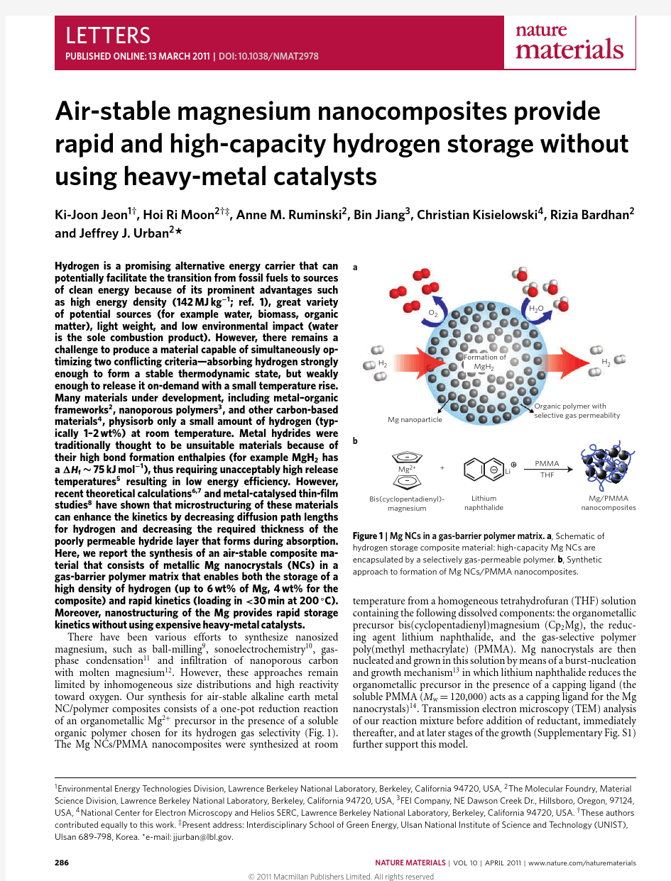
Figure 1|Mg NCs in a gas-barrier polymer matrix.a ,Schematic of hydrogen storage composite material:high-capacity Mg NCs are encapsulated by a selectively gas-permeable polymer.b ,Synthetic approach to formation of Mg NCs/PMMA nanocomposites.
temperature from a homogeneous tetrahydrofuran (THF)solution containing the following dissolved components:the organometallic precursor bis(cyclopentadienyl)magnesium (Cp 2Mg),the reduc-ing agent lithium naphthalide,and the gas-selective polymer poly(methyl methacrylate)(PMMA).Mg nanocrystals are then nucleated and grown in this solution by means of a burst-nucleation and growth mechanism 13in which lithium naphthalide reduces the organometallic precursor in the presence of a capping ligand (the soluble PMMA (M w =120,000)acts as a capping ligand for the Mg nanocrystals)14.Transmission electron microscopy (TEM)analysis of our reaction mixture before addition of reductant,immediately thereafter,and at later stages of the growth (Supplementary Fig.S1)further support this model.
Cumulative fraction
0.2
0.40.60.81.01.2(100)
(002)
(101)
(102)
(110)
(103)After synthesis
After 3-day air exposure
Mg MgO Mg(OH)2
2 (°)
θ0
24681000.10.20.3
0.4a
d
b c
I n t e n s i t y (a .u .)
Particle size (nm)
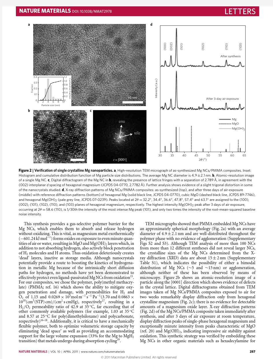
Figure 2|Veri?cation of single crystalline Mg nanoparticles.a ,High-resolution TEM micrograph of as-synthesized Mg NCs/PMMA composites.Inset:
Histogram and cumulative distribution function of Mg particle size distributions.The average Mg NC diameter is 4.9±2.1nm.b ,Atomic-resolution image of a single Mg NC.c ,Digital diffractogram of the Mg NC in b ,revealing the presence of lattice fringes with a separation of 2.789?,in agreement with the (002)interplanar d spacing of hexagonal magnesium (JCPDS 04-0770,2.7782?).Further analysis shows evidence of a slight trigonal distortion in some of the nanocrystals studied.d ,X-ray diffraction patterns of Mg NCs/PMMA composites:as-synthesized (top),and after three days of air-exposure
(middle)with reference diffraction patterns (bottom)of hexagonal Mg (solid black line,JCPDS 04-0770),cubic MgO (dashed black line,JCPDS 89-7746),and hexagonal Mg(OH)2(pale grey line,JCPDS 07-0239).Peaks located at 2θ=32.2?,34.4?,36.6?,47.8?,57.4?and 63.1?are assigned to the (100),(002),(101),(102),(110),and (103)planes of hexagonal magnesium,respectively.The highest intensity Mg(OH)2peak after 3days of air exposure,
occurring at 2θ=58.6(110),is 1/30th the intensity of the most intense Mg peak (101),and only two times the intensity of the root-mean-squared baseline noise intensity.
This synthesis provides a gas-selective polymer barrier for the Mg NCs,which enables them to absorb and release hydrogen without oxidizing.This is vital,as magnesium metal exothermically (?601.24kJ mol ?1)forms oxides on exposure to even minute quan-tities of air or water,resulting in MgO and Mg(OH)2layers which,in addition to not absorbing hydrogen,also actively block penetration of H 2molecules and H atoms.Thus oxidation deleteriously creates ‘dead’layers,inactive as storage media.Although nanocrystals potentially provide a route to boosting the kinetics of hydrogena-tion in metallic Mg because of the intrinsically short diffusion paths for hydrogen,no methods have yet been demonstrated to effectively protect even ligand-passivated Mg NCs from oxidation 15.For our composites,we chose the polymer,poly(methyl methacry-late)(PMMA;ref.16)which shows the ability to mitigate oxy-gen penetration and damage,with permeabilities for H 2and O 2of 1.15and 0.0269×10⁵mol m ?1s ?1Pa ?1(3.70and 0.0863×10¹⁰(cm 3(STP)cm)/(cm 2s cmHg),respectively 17,resulting in a H 2/O 2permeability ratio of 42.9at 35?C,far exceeding that of other commonly available polymers (for example,1.03at 35?C and 8.57at 25?C for poly(dimethylsiloxane)and polycarbonate,respectively)16–18.Additionally,it is critical to have a mechanically flexible polymer,both to optimize volumetric storage capacity by eliminating ‘dead space’as well as providing an accommodating support for the large volume expansion (33%for the Mg to MgH 2transition)that metals undergo during absorption cycling 19.
TEM micrographs showed that PMMA embedded Mg NCs have an approximately spherical morphology (Fig.2a)with an average diameter of 4.9±2.1nm and are well-distributed throughout the polymer phase with no evidence of agglomeration (Supplementary Figs S2and S3).Although TEM analysis of more than 100NCs from more than 12different syntheses did not reveal larger NCs,the crystalline sizes of the Mg NCs determined from the X-ray diffraction (XRD)data are about 15±2nm (Supplementary Table S1),which indicates the possibility of either a bimodal distribution of Mg NCs (~5and ~15nm)or agglomeration,although neither of these has been observed by means of microscopy.Figure 2b shows an atomic-resolution image of a particle along the [0001]direction which shows evidence of defects in the crystal lattice.Digital diffractograms obtained from TEM images taken of Mg NCs/PMMA composites exposed to air for two weeks remarkably display diffraction only from hexagonal crystalline magnesium (Fig.2c);there is no evidence for detectable amounts of a magnesium oxide layer.X-ray diffraction patterns (Fig.2d)of the Mg NCs/PMMA composite taken immediately after synthesis,and after 3days of air exposure at room temperature,display diffraction peaks of single-phase hexagonal magnesium and exceptionally minute intensity from peaks characteristic of MgO (ref.20)and Mg(OH)2,indicating impressive air stability against oxidation.This synthetic strategy was verified by embedding these Mg NCs in other organic materials such as hexadecylamine for
76
5
43210H y d r o g e n a b s o r p t i o n (w t %)
H y d r o g e n a b s o r p t i o n
(w t %)
10
20
30
4050
60
70
80
Time (min)
765432100
5
1015202530
Time (h)
5.97 wt%
0 wt%
35 bar H 20 bar H 2
44 μm Mg powder
5 nm Mg NCs/PMMA composite [?ln(1? )]
1/n = kt 2
1
?1
?2
?3
ln t
?1
?2
?3
?4
?5
l n [?l n (1? )]
ααn = 1.1740, (R 2 = 0.998)
a
b
Figure 3|Hydrogen absorption in Mg NCs/PMMA composites.a ,Enhancement in hydrogen absorption properties of Mg NCs/PMMA composites
(absorption at 200?C and 35bar)in comparison to bulk Mg.The Mg NCs/PMMA composites display a calculated hydrogen absorption capacity value of 5.97wt%Mg (~4wt%total).Inset:Hydrogen absorption/desorption cycling at 200?C.b ,The initial growth mechanism of MgH 2in Mg NCs/PMMA composites.Hydrogen absorption data shown in a (initial 6min)was used to correlate with a Johnson–Mehl–Avrami model (equation (1)).
comparison,and the resulting X-ray diffraction spectra indicate immediate oxidation (Supplementary Fig.S4).Thermogravimetric analysis of the Mg NCs/PMMA composites indicates that 61%of the total nanocomposite weight is hydrogen storage active material (Supplementary Fig.S5).
The hydrogen absorption capacity for Mg NCs/PMMA composites was measured in relation to a known reference material,bulk Mg (44μm),using a Sieverts PCT-Pro at 35bar H 2and 200?C (Fig.3a).The bulk Mg shows no weight increase on hydrogen exposure,indicating a lack of MgH 2formation.However,the Mg NCs/PMMA composites display a sharp weight increase on hydrogen exposure,with a steep slope of hydrogenation occurring during the first 6min,which plateaus off to constant mass in <30min.The differences in slope between the first 6min and the remainder of the absorption curve are attributed to a change in the rate-limiting mechanism for hydrogen uptake 21.It was found that the hydrogen absorption capacity of the Mg NCs/PMMA composite was well-preserved through three absorption/desorption cycles (Fig.3a inset),however slightly decreased dehydriding kinetics were observed after the third cycle as evinced from the decreased slope of descent.This marginal degradation is probably due to material fatigue owing to relaxation of structural defects,but more detailed investigation is necessary.From the measured absorption isotherm,a calculated hydrogen absorption capacity value of 5.97wt%Mg (~4wt%in overall composite mass)is reported.Thus,these composites absorb 78.6%of the theoretical value of magnesium.The calculated experimental volumetric hydrogen capacity of the composites is 55g l ?1(the theoretical capacity for the Mg NCs/PMMA composites is 70g l ?1).This value exceeds the volumetric capacity of compressed hydrogen (10,000psi,30g l ?1)by 180%,demonstrating that Mg NCs/PMMA composites provide a viable storage alternative to gas tanks.In comparison,bulk Mg (<37μm)absorbs only ±2%of the theoretical hydrogen absorption value within 10min at 35bar,and requires prohibitively high temperatures (400?C)to do so 22.
To verify that hydrogen uptake in this Mg NCs/PMMA composite is due to metal-hydride formation and not polymer adsorption,time-resolved low-loss electron energy loss spectroscopy (EELS)was performed on MgH 2NCs/PMMA composites using a monochromated and aberration-corrected transmission electron microscope at 80kV (ref.23).Figure 4displays the time resolved and normalized EELS spectrum of
the
C o u n t s (a .u .)
Energy loss (eV)
Figure 4|Time-resolved monitoring of hydrogen desorption from MgH 2NCs/PMMA composites.Low-loss EELS spectra of MgH 2NCs/PMMA using the TEAM 0.5microscope at 80kV.Mg plasmon energy loss:10.5eV,and MgH 2plasmon energy loss:14.6eV.All spectra were normalized to the Mg peak position at 10.5eV.Note that peaks occurring at a constant
interval of ~10.3eV (located at 21.0and 31.3eV)are Mg plasmon replicas.
MgH 2NCs/PMMA composites.At time 0s,two distinct,intense EELS peaks are observed at 10.5and 14.6eV,corresponding to the co-existence of pure Mg and MgH 2,respectively 24.As the exposure time to the electron beam increases,the relative intensity of the Mg peak increases in relation to the intensity of the MgH 2peak.The intensity ratio (I MgH2/I Mg )reduces from 2.04to 0during the 5min of beam exposure owing to hydrogen loss from the hydride phase.Notably,the presence of the characteristic MgO peak at about 22.3eV (Supplementary Fig.S6)was not observed in the sample,further evidence supporting the remarkable oxidative stability of these composites.
Theoretical calculations indicate that Mg NCs can exhibit more favourable thermodynamics (that is,lower enthalpies for hydride formation)than bulk Mg owing to the destabilization of MgH 2formation 6,7.Additionally,it is known that the chemical reactivity of Mg NCs positively correlates to the large metal surface area and the short diffusion path of hydrogen 25.We postulate that
nanostructuring of magnesium in the nanocomposites obviates the need for expensive heavy-metal catalysts by reducing the activation energy for absorption and release of hydrogen11.To assess this,we have determined an activation energy(E a)from analysis of the absorption and release of hydrogen at three different temperatures(Supplementary Fig.S7).We measure E a values of25 and79kJ mol?1for absorption and desorption,respectively,which are comparable to,and in some cases lower than,those obtained from similar materials requiring the use of heavy-metal catalysts26.
Hydrogen absorption in a crystalline solid can either occur as a result of isotropic diffusion and random nucleation,or preferential nucleation along certain favourable crystal axes. Further optimization of these materials requires a physical understanding of the mechanism of hydride formation in the nanocomposite,which can be obtained by means of modelling of the uptake kinetics.Here,experimental absorption data of the Mg NCs/PMMA composite materials was fitted with several basic empirical and theoretical kinetic models developed by Avrami27,which enable characterization of the mechanism and dimensionality of MgH2phase formation.Experimental data from the first6min of hydrogen absorption in the Mg NCs/PMMA composites was fitted with the Johnson–Mehl–Avrami model(equation(1)):
[?ln(1?α)]1/n=kt(1) whereαis the hydrogenated fraction of Mg,k is the phase transformation constant,t is time,and n is the dimensionality of MgH2growth.This model assumes a constant interface velocity of MgH2formation21.
By using the dimensionality factor(n)in equation(1)as a fitting parameter,and solving for the best fit(R2)of the data,the dimensionality of the growth of the MgH2phase was determined to be1.1740(R2=0.998).There exist numerous growth and nucleation scenarios consistent with a value of n=1,including nucleation and growth along one-dimensional(1D)dislocation lines and thickening of cylinders,needles,and plates28.We posit that MgH2growth in the individual Mg nanocrystals in the composite occurs nearly one-dimensionally along columnar defects as they are exposed to H2gas(Fig.3b),as consistent with the high-resolution TEM(HRTEM)observations(Fig.2b), although other possible scenarios cannot be excluded at present. To exclude other competing mechanisms,the MgH2hydrogen absorption data was fitted to additional Johnson–Mehl–Avrami models of varying dimensionality and mechanism(equations2–4in Supplementary Table S2).These additional Johnson–Mehl–Avrami models(Supplementary Fig.S8)had comparatively poor fits(R2= 0.914–0.964)compared with the growth model of equation(1), supporting the hypothesis that hydrogen absorption in the Mg NCs/PMMA composites occurs by means of1D growth.This novel, 1D growth mechanism is also consistent with our measurement of rapid kinetics in the Mg NCs,as hydrogen diffusion through Mg hydride layers is many orders of magnitude slower than the diffusion of hydrogen atoms through lattice vacancies25,29.Analysis of HRTEM images of the composites provides evidence for the existence of defects in the Mg NCs(Fig.2b).It is known that hydrogen atoms can more easily diffuse along1D line defects, which can act as hydrogen trap sites.Thus,we posit that in Mg NCs/PMMA composites,hydrogen atoms rapidly nucleate and accumulate along these defects and form a metal hydride layer in one dimension,followed by subsequent growth and thickening from the pure metallic core.This conclusion also corroborates recent published results on hydride growth in MgH2fibres19.
In summary,we have developed a new,simple method to synthesize air-stable crystalline Mg NCs/PMMA composites by en-capsulation in a polymer with selective gas permeability,protecting the NCs from O2and H2O.The Mg NCs/PMMA composites impressively showed no oxidation in HRTEM diffractograms after two weeks of air exposure.Rapid uptake(<30min at200?C)of hydrogen was achieved with a high capacity(~6wt%in Mg,~4% overall)in the absence of heavy-metal catalysts,demonstrating a volumetric capacity(55g l?1)greater than that of compressed H2gas.Theoretical modelling of the experimental data with a Johnson–Mehl–Avrami model indicates that hydrogenation of Mg NCs proceeds through1D growth,which can occur along line defects in the Mg NCs,as observed by means of HRTEM.On the whole,this approach of synthesizing nanosized air-sensitive metal nanocrystals protected in a gas-selective polymer provides new opportunities in low-cost high-capacity hydrogen storage media, batteries and fuel cells.
Methods
The Mg NCs/PMMA composites were prepared in an inert atmosphere.
Bis(cyclopentadienyl)magnesium(Cp2Mg)(154mg,1.00mmol)was reduced
in a solution of tetrahydrofuran(9ml)containing lithium(9mg,1.29mmol), naphthalene(120mg,0.94mmol),and poly(methyl methacrylate)(60mg), stirring under Ar atmosphere overnight.The resultant product was isolated by centrifugation,washed with tetrahydrofuran,and dried under an inert atmosphere prior to performing all characterization and measurements.The hydrogenation experiments were performed on the composite samples after first annealing in
a helium environment for>24h to remove solvent and unreacted monomer. The hydrogenation/desorption tests were performed at200?C and35and
0bar of H2respectively.
Received5November2010;accepted28January2011; published online13March2011
References
1.Jain,I.P.,Lal,C.&Jain,A.Hydrogen storage in Mg:A most promising
material.Int.J.Hydrog.Energy35,5133–5144(2010).
2.Murray,L.J.,Dinc?,M.&Long,J.R.Hydrogen storage in metal–organic
frameworks.Chem.Soc.Rev.38,1294–1314(2009).
3.Germain,J.,Fréchet,J.M.J.&Svec,F.Nanoporous polymers for hydrogen
storage.Small5,1098–1111(2009).
4.Patchkovskii,S.et al.Graphene nanostructures as tunable storage media for
molecular hydrogen.Proc.Natl https://www.doczj.com/doc/387889502.html,A102,10439–10444(2005).
5.Schlapbach,L.&Zuttel,A.Hydrogen-storage materials for mobile applications.
Nature414,353–358(2001).
6.Cheung,S.,Deng,W-Q.,van Duin,A.C.T.&Goddard,W.A.ReaxFF MgH
reactive force field for magnesium hydride systems.J.Phys.Chem.A109,
851–859(2005).
7.Wagemans,R.W.P.,van Lenthe,J.H.,de Jongh,P.E.,van Dillen,A.J.&
de Jong,K.P.Hydrogen storage in magnesium clusters:Quantum chemical study.J.Am.Chem.Soc.127,16675–16680(2005).
8.Zahiri,B.,Amirkhiz,B.S.&Mitlin,D.Hydrogen storage cycling of MgH2
thin film nanocomposites catalyzed by bimetallic Cr Ti.Appl.Phys.Lett.97, 083106(2010).
9.Aguey-Zinsou,K.F.,Ares Fernandez,J.R.,Klassen,T.&Bormann,R.Effect of
Nb2O5on MgH2properties during mechanical milling.Int.J.Hydrog.Energy 32,2400–2407(2007).
10.Haas,I.&Gedanken,A.Synthesis of metallic magnesium nanoparticles by
https://www.doczj.com/doc/387889502.html,mun.1795–1797(2008).
11.Li,W.,Li,C.,Ma,H.&Chen,J.Magnesium nanowires:Enhanced kinetics for
hydrogen absorption and desorption.J.Am.Chem.Soc.129,6710–6711(2007).
12.de Jongh,P.E.et al.The preparation of carbon-supported
magnesium nanoparticles using melt infiltration.Chem.Mater.19,
6052–6057(2007).
13.Park,J.,Joo,J.,Kwon,S.G.,Jang,Y.&Hyeon,T.Synthesis of monodisperse
spherical nanocrystals.Angew.Chem.Int.Ed.46,4630–4660(2007).
14.Grubbs,R.B.Roles of polymer ligands in nanoparticle stabilization.Polym.Rev.
47,197–215(2007).
15.Kalidindi,S.B.&Jagirdar,B.R.Highly monodisperse colloidal magnesium
nanoparticles by room temperature digestive ripening.Inorg.Chem.48,
4524–4529(2009).
16.Mark,J.E.(ed.)Polymer Data Handbook(Oxford Univ.Press,1999).
17.Min,K.E.&Paul,D.R.Effect of tacticity on permeation properties of
poly(methyl methacrylate).J.Polym.Sci.Polym.Phys.26,1021–1033(1988).
18.Bhide,B.D.&Stern,S.A.Permeability of silicone polymers to hydrogen.
J.Appl.Polym.Sci.42,2397–2403(1991).
19.Zlotea,C.,Lu,J.&Andersson,Y.Formation of one-dimensional MgH2
nano-structures by hydrogen induced disproportionation.J.Alloys Compounds 426,357–362(2006).
20.Moon,H.R.,Urban,J.J.&Milliron,D.J.Size-controlled synthesis and
optical properties of monodisperse colloidal magnesium oxide nanocrystals.
Angew.Chem.Int.Ed.48,6278–6281(2009).
21.Rudman,P.S.Hydrogen-diffusion-rate-limited hydriding and dehydriding
kinetics.J.Appl.Phys.50,7195–7199(1979).
22.Vigeholm,B.,Kjoller,J.&Larsen,B.Magnesium for hydrogen storage.
J.Less-Common Met.74,341–350(1980).
23.Kisielowski,C.et al.Detection of single atoms and buried defects in
three dimensions by aberration-corrected electron microscope with
0.5-?information limit.Microsc.Microanal.14,469–477(2008).
24.Danaie,M.,Tao,S.X.,Kalisvaart,P.&Mitlin,D.Analysis of deformation
twins and the partially dehydrogenated microstructure in nanocrystalline
magnesium hydride(MgH2)powder.Acta Mater.58,3162–3172(2010). 25.Dornheim,M.,Eigen,N.,Barkhordarian,G.,Klassen,T.&Bormann,R.
Tailoring hydrogen storage materials towards application.Adv.Eng.Mater.8, 377–385(2006).
26.Denis,A.,Sellier,E.,Aymonier,C.&Bobet,J.L.Hydrogen sorption properties
of magnesium particles decorated with metallic nanoparticles as catalyst.
J.Alloys Compounds476,152–159(2009).
27.Avrami,M.Granulation,phase change,and microstructure—kinetics of phase
change.III.J.Phys.Chem.9,177–184(1941).
28.Christian,J.W.The Theory of Transformations in Metals and Alloys,Part I:
Equilibrium and General Kinetic Theory2nd edn(Pergamon,1975).
29.Ragone,D.V.Thermodynamics of Materials(Wiley,1995).Acknowledgements
Work at the Molecular Foundry and the National Center for Electron Microscopy was supported by the Office of Science,Office of Basic Energy Sciences,of the US Department of Energy under Contract No.DE-AC02-05CH11231.J.J.U.,K-J.J.,H.R.M.,and R.B. are supported under the US Department of Energy Hydrogen Storage Program.A.M.R. is supported as part of the Center for Nanoscale Control of Geologic CO2,an Energy Frontier Research Center funded by the US Department of Energy,Office of Science, Office of Basic Energy Sciences under Contract No.DE-AC02-05CH11231.We thank J.R.Long and T.J.Richardson for critical discussions and exchange,and appreciate the support of S.Mao for PCI measurement.
Author contributions
J.J.U.,K-J.J.,and H.R.M.conceived and designed the experiments.K-J.J.,H.R.M,
A.M.R.,and R.
B.performed the experiments.K-J.J,B.J.and
C.K contributed towards TEM,EELS acquisition and analysis.K-J.J.,H.R.M.,A.M.R.,and J.J.U.analysed the data and wrote the manuscript.All authors discussed the results and commented
on the manuscript.
Additional information
The authors declare no competing financial interests.Supplementary information accompanies this paper on https://www.doczj.com/doc/387889502.html,/naturematerials.Reprints and permissions information is available online at https://www.doczj.com/doc/387889502.html,/reprintsandpermissions. Correspondence and requests for materials should be addressed to J.J.U.
储氢材料的储氢原理与研究现状 氢能,即氢气中所含有的能量。具有环境友好、资源丰富、热值高、燃烧性能好、潜在经济效益高等特点[2]。目前,能源危机和环境危机日益严重。许多国家都在加紧部署、实施氢能战略,如美国针对运输机械的“Freedom CAR”计划和针对规模制氢的“Future Gen”计划,日本的“New Sunshine”计划及“We-NET”系统,欧洲的“Framework”计划中关于氢能科技的投人也呈现指数上升趋势[3]。但是,氢能的使用至今未能商业化,主要的制约因素就是存储问题难以解决。因此,氢能的利用和研究成为是当今科学研究的热点之一。而寻找性能优越、安全性高、价格低廉、环保的储氢材料则成为氢能研究的关键。 目前,氢可以以高压气态液态、金属氢化物、有机氢化物和物理化学吸附等形式储存。高压气态液态[4]储氢发展的历史 较早,是比较传统而成熟的方法,无需任何材料做载体,只需耐压或绝热的容器就行,但是储氢效率很低,加压到15MPa时质量储氢密度不超过3 %。而且存在很大的安全隐患,成本也很高。 金属氢化物[5-7]储氢开始于1967年,Reilly等报道Mg2Cu能大量储存氢气,接着1970年菲利浦公司报道LaNi5在室温下能可逆吸储与释放氢气,到1984年Willims制出镍氢化物电池,掀起稀土基储氢材料的开发热潮[8-9]。金属氢化物储氢的原理是氢原子进入金属价键结构形成氢化物。有稀土镧镍、钛铁合金、镁系合金、钒、铌、锆等多元素系合金。具体有NaH-Al-Ti、 Li3N-LiNH2、MgB2-LiH、MgH2-Cr2O3及Ni(Cu,Rh)-Cr-FeO x等物质,
材料学《第二课堂》课程论文题目:TiO2半导体纳米材料姓名: 学号:
目录 1. 课程设计的目的 (1) 2. 课程设计题目描述和要求 (1) 3. 课程设计报告内容 (1) 3.1 TiO2半导体纳米材料的特性 (1) 3.2 TiO2半导体纳米材料的制备方法 (3) 3.3 TiO2半导体纳米材料的表征手段 (3) 3.4 TiO2半导体纳米材料的发展现状与趋势 (4) 4. 结论 (5)
1.课程设计的目的 本课程论文的主要目的是论述TiO2半导体纳米材料,通过简要概述TiO2半导体纳米材料的特性、制备方法、表征手段及发展现状与趋势等相关方面的内容。通过这次课设,了解TiO2半导体纳米材料,巩固课堂上所学的有关纳米材料的有关知识,提高自己应用所学知识和技能解决实际问题的能力。 2.课程设计的题目描述及要求 课程设计的题目:TiO2半导体纳米材料 TiO2半导体纳米材料由于它具有不同于体材料的光学非线性和发光性质,在未来光开关、光存储、光快速转换和超高速处理等方面具有巨大的应用前景。本文就TiO2半导体纳米材料的主要制备方法与表征手段做一全面总结。 3.课程设计报告内容 3.1 TiO2半导体纳米材料的特性 1、光学特性 TiO2半导体纳米粒子(1~ 100 nm ) [2]由于存在着显著的量子尺寸效应, 因此它们的光物理和光化学性质迅速成为目前最活跃的研究领域之一, 其中TiO2半导体纳米粒子所具有的超快速的光学非线性响应及(室温) 光致发光等特性倍受世人瞩目。通常当半导体粒子尺寸与其激子玻尔半径相近时, 随着粒子尺寸的减小, 半导体粒子的有效带隙增加, 其相应的吸收光谱和荧光光谱发生蓝移, 从而在能带中形成一系列分立的能级[1]。 2、光电催化特性 1)TiO2半导体纳米粒子优异的光电催化活性 近年来, 对纳米TiO2半导体粒子研究表明: 纳米粒子的光催化活性均明显优于相应的体相材料。我们认为这主要由以下原因所致: ①TiO2半导体纳米粒子所具有的量子尺寸效应使其导带和价带能级变成分立的能级, 能隙变宽, 导带电位变得更负, 而价带电位变得更正。[1]这意味着TiO2半导体纳米粒子获得了更强的还原及氧化能力, 从而催化活性随尺寸量子化程度的提高而提高[5]。 ②对于TiO2半导体纳米粒子而言, 其粒径通常小于空间电荷层的厚度, 在离开粒子中心L距离处的势垒高度可以表述为[1]: 公式(1) 这里LD是半导体的Debye 长度, 在此情况下, 空间电荷层的任何影响都可忽略, 光生载流子可通过简单的扩散从粒子内部迁移到粒子表面而与电子给体或受体发生还原或氧化反应。计算表明: 在粒径为1Lm 的T iO 2 粒子中, 电子从体内扩散到表面的时间约为100n s, 而在粒径为10 nm 的微粒中只有10 p s。因此粒
一、前言 随着社会的发展,环境保护问题已经越来越为人们所重视。酸雨、温室效应、城市热岛效应等等 或初露倪端,或已对人类造成巨大的危害,这些环保问题的产生在很大程度上与人类大量使用化石能 源有关。同时,由于能源消耗量的迅猛增加,化石能源将不能满足经济高速发展的需求,需要开发新 的能源。在我国开发清洁的新能源体系更具有重要意义。 氢可以地球上近于无限的水为原料来制备,其燃烧产物也是水,具有零污染的优点,有望在石油中国论文联盟https://www.doczj.com/doc/387889502.html, 时代末期成为一种主要的二次能源。氢能技术的发展,已在航天技术中得到了成功的应用。 氢是一种危险,易燃易爆的气体,在使用中必须保证安全,因此,一种安全、高能量密度(包括体积能量密度和重量能量密度)、低成本、使用寿命长的氢储、输技术的应用需求已越来越迫切。 二、目前主要的储氢方式 近年来研究较多的储氢方式有:(1)金属氢化物储氢;(2)液化储氢;(3)吸附储氢;(4)压缩储氢。 2.1金属氢化物储氢 氢和氢化金属之间可以进行可逆反应,当外界有热量加给氢化物时,它就分解为氢化金属并释放 出氢气。用来储氢的金属大多是由多种元素构成的合金,目前世界上研究成功的合金大致分为:(1)稀土镧镍,每公斤镧镍合金可储氢153L;(2)铁钛合金,储氢量大,价格低月在常温常压下释放氢;(3)镁系合金,是吸氢量最大的元素,但需要在287℃条件下才能释放氢,而且吸收氢十分缓慢;(4)钒、铌、铅等多元素系,这些金属本身是稀贵金属,因此只适用于某 些特殊场合。 与其它储氢方式相比,金属氢化物储氢具有压力平稳,充氢简单、方便、安全等优点,单位体积贮氢的密度,是相同温度、压力条件下气态氢的1000倍。该储氢方式存在的问题为在大规模应用中如 何提高储氢材料的储氢量和降低材料成本,节约贵重金属。国际能源机构确定的未来新型储素材料的标准为储氢量应大于5Wt%,并且能在温和条件下吸放氢。根据这一标准,目前的储氢合金大多尚不能满足这一性能要求。 2.2液化储氢 将氢气冷却到-253℃时氢气即可液化。液氢储存方式的质量能量密度最大,是一种轻巧紧凑的方式。但氢气液化成本高,能量损失大(氢液化所需能量为液化氢燃烧产热额的30%),且存在蒸发损 失。液氢贮存工艺首先用于宇航中,但需要极好的绝热装置来隔热,才能防止液态氢不会沸腾汽化, 导致液体贮存箱非常庞大。 2.3吸附储氢 C.CarPetis和W.Peschka是首先提出在低温条件下氢气能够在活性炭中吸附储存的两位学者。他们提出可以考虑将低温吸附刘运用到大型氢气储存中,并研究得到了在温度为-195℃和-208℃,压力为0-4.15MPa时,氢在多种活性炭上的吸附等温线:压力为4.2MPa 时,氢气在活性炭上的吸附容量分别可以达到 6.8wt%和 8.2wt%在果等温膨胀到0.2MPa,则吸附容量为4.2wt%和5.2wt%。 在一个最近的研究中,Hynek在27℃和-83℃条件下测试了一系列吸附剂,如活性炭、碳黑、碳气凝胶 以及碳分子筛等。测试结果为:在0-20MPa压力范围内,随着压力的增大,吸附剂的储氢量只有少 量的增加。 目前吸附储氢材料研究的热点是碳纳米材料。由于碳纳米材料中独特的晶格排列结构,其储氢数量大大的高过了传统的吸附储氢材料。碳纳米管产生一些带有斜口形状的层板,层
?综合评述? 半导体纳米材料的光学性能及研究进展Ξ 关柏鸥 张桂兰 汤国庆 (南开大学现代光学研究所,天津300071) 韩关云 (天津大学电子工程系,300072) 摘要 本文综述了近年来半导体纳米材料光学性能方面的研究进展情况,着重介绍了半导体纳米材料的光吸收、光致发光和三阶非线性光学特性。 关键词 半导体纳米材料;光学性能 The Optica l Properties and Progress of Nanosize Sem iconductor M a ter i a ls Guan B ai ou Zhang Gu ilan T ang Guoqing H an Guanyun (Institute of M odern Op tics,N ankaiU niversity,T ianjin300071) Abstract T he study of nano size sem iconducto r particles has advanced a new step in the understanding of m atter.T h is paper summ arizes the p rogress of recent study on op tical p roperties of nano size sem icon2 ducto r m aterials,especially emphasizes on the op tical2abso rp ti on,pho to lum inescence,nonlinear op tical p roperties of nano size sem iconducto r m aterials. Key words nano size sem iconducto r m aterials;op tical p roperties 1 引言 随着大规模集成的微电子和光电子技术的发展,功能元器件越来越微细,人们有必要考察物质的维度下降会带来什么新的现象,这些新的现象能提供哪些新的应用。八十年代起,低维材料已成为倍受人们重视的研究领域。 低维材料一般分为以下三种:(1)二维材料,包括薄膜、量子阱和超晶格等,在某一维度上的尺寸为纳米量级;(2)一维材料,或称量子线,线的粗细为纳米量级;(3)零维材料,或称量子点,是尺寸为纳米量级的超细微粒,又称纳米微粒。随着维数的减小,半导体材料的电子能态发生变化,其光、电、声、磁等方面性能与常规体材料相比有着显著不同。低维材料开辟了材料科学研究的新领域。本文仅就半导体纳米微粒和由纳米微粒构成的纳米固体的光学性能及其研究进展情况做概括介绍。2 半导体纳米微粒中电子的能量状态 当半导体材料从体块减小到一定临界尺寸以后,其载流子(电子、空穴)的运动将受限,导致动能的增加,原来连续的能带结构变成准分立的类分子能级,并且由于动能的增加使得能隙增大,光吸收带边向短波方向移动(即吸收蓝移),尺寸越小,移动越大。 关于半导体纳米微粒中电子能态的理论工作最早是由AL.L.Efro s和A.L.Efro s开展的[1]。他们采用有效质量近似方法(E M A),根据微粒尺寸R与体材料激子玻尔半径a B之比分为弱受限(Rμa B,a B=a e+ a h,a e,a h分别为电子和空穴的玻尔半径)、中等受限(a h 半导体器件原理简明教程习题答案 傅兴华 1.1 简述单晶、多晶、非晶体材料结构的基本特点. 解 整块固体材料中原子或分子的排列呈现严格一致周期性的称为单晶材料; 原子或分子的排列只在小范围呈现周期性而在大范围不具备周期性的是多晶材料; 原子或分子没有任何周期性的是非晶体材料. 1.6 什么是有效质量,根据E(k)平面上的的能带图定性判断硅鍺和砷化镓导带电子的迁移率的相对大小. 解 有效质量指的是对加速度的阻力.k E h m k ??=2 1*1 由能带图可知,Ge 与Si 为间接带隙半导体,Si 的Eg 比Ge 的Rg 大,所以Ge μ>Si μ.GaAs 为直接带隙半导体,它的跃迁不与晶格交换能量,所以相对来说GaAs μ>Ge μ>Si μ. 1.10 假定两种半导体除禁带宽度以外的其他性质相同,材料1的禁带宽度为1.1eV,材料2 的禁带宽度为 3.0eV,计算两种半导体材料的本征载流子浓度比值,哪一种半导体材料更适合制作高温环境下工作的器件? 解 本征载流子浓度:)exp( )( 1082.42 15 T dp dn i k Eg m m m n ?= Θ两种半导体除禁带以外的其他性质相同 ∴)9.1exp()exp()exp(0.31.121T k k k n n T T ==-- ΘT k 9.1>0 ∴21n n > ∴在高温环境下2n 更合适 1.11 在300K 下硅中电子浓度330102-?=cm n ,计算硅中空穴浓度0p ,画出半导体能带图, 判断该半导体是n 型还是p 型半导体. 解 3 173 21002 02 0010125.1102)105.1(p -?=??==→=cm n n n p n i i ∴>00n p Θ是p 型半导体 1.16 硅中受主杂质浓度为31710-cm ,计算在300K 下的载流子浓度0n 和0p ,计算费米能级相 对于本征费米能级的位置,画出能带图. 解 3 17010-==cm N p A 200i n p n = T=300K →3 10 105.1-?=cm n i 330 2 01025.2-?==∴cm p n n i 00n p >Θ ∴该半导体是p 型半导体 )105.110ln(0259.0)ln(10 17 0??==-i FP i n p KT E E 纳米储氢电极材料主要有碳纳米管、镁镍合金和镁钛合金 Mg2 Ni纳米晶储氢材料 性能:它具有储氢容量高,吸放氢平台好,质量轻,资源丰富等优点,但要能达到实用化的目的就必须解决其在室温下吸放氢动力学性能差,表面容易形成氧化膜等缺点。 目前,在镁基储氢合金的开发研究中,现已有Mg2Ni ,Mg2Cu ,Mg2La系储氢合金,还有 一系列的多元MgNi系储氢合金。 制备方法采用机械合金化方法,即使用高能球磨机进行球磨制备 1. 采用机械合金化方法制备了Mg Ni 合金粉末,其晶 粒度在10nm左右。 2. 在较高的速度下球磨可以使生成Mg Ni 合金的时间提 前,完全合金化的过程缩短,还有利于减轻焊合提高球磨效率。 3. 过程控制剂的加入以及循环变速运转可以缓和焊合 现象的发生。 4. 初步的研究结果表明:Mg Ni 纳米晶粉末在室温下即 可吸氢,贮氢性能较之传统方法制备的材料有显著改善。 传统方法制备的Mg Ni 在温度低于250°C时不产生吸 2 氢现象,在经历一个前期活化过程之后,吸放氢实验在250 8 °C~350°C,氢气压力1.5~2.0MPa下完成。 将机械合金化制备的Mg Ni 纳米晶粉末在金属高压系 2 统进行贮氢性能研究。称取一定量样品放入反应室中,真空加热除气后,冷却到室温,放入一定量的氢气(氢气纯度大于99 %),观察粉末在室温下的吸氢情况。 储氢碳纳米管 碳纳米管CNTs,Carbon Nanotubes 是一种主要由碳六 边形弯曲处为碳五边形和碳七边形组成的单层或多层 纳米管状材料。管的内径在几个纳米到几十个纳米之间, 长度可达微米量级。仅有一层石墨片层结构的单层管被 称为单壁碳纳米管SWNTs, Single - Walled carbon nan tubes ,有多层石墨片alled carbon nan tubes 。单壁碳纳米管 是碳纳米管的一层结构的多层管被称为多壁碳纳米 管MWNTs,Multi - W种极限状态,管径较小,直径一般为1~ 6nm,最小的直径大约为014nm,其结构中的缺陷不易存 在,具有较高的均匀性和一致性。多壁碳纳米管的直径一 般为几纳米到几十纳米,长度为几十纳米到微米,层数从 2~50不等,层间距约为0134nm。 (文献参考:Mg_2Ni纳米晶储氢材料的机械合金化制备工艺研究) 物理吸附 摘要:讨论了当前国内外主要的几种半导体纳米材料的制备工艺技术,包括物理法和化学法两大类下的几种,机械球磨法、磁控溅射法、静电纺丝法、溶胶凝胶法、微乳液法、模板法等,并分析了以上几种纳米材料制备技术的优缺点关键词:半导体纳米粒子性质;半导体纳米材料;溶胶一凝胶法;机械球磨法;磁控溅射法;静电纺丝法;微乳液法;模板法;金属有机物化学气相淀积引言 半导体材料(semiconductormaterial)是一类具有半导体性能(导电能力介于导体与绝缘体之间,电阻率约在1mΩ·cm~1GΩ·cm范围内)。相对于导体材料而言,半导体中的电子动能较低,有较长的德布罗意波长,对空间限域比较敏感。半导体材料空间中某一方向的尺寸限制与电子的德布罗意波长可比拟时,电子的运动被量子化地限制在离散的本征态,从而失去一个空间自由度或者说减少了一维,通常适用体材料的电子的粒子行为在此材料中不再适用。这种自然界不存在,通过能带工程人工制造的新型功能材料叫做半导体纳米材料。现已知道,半导体纳米粒子结构上的特点(原子畴尺寸小于100nm,大比例原子处于晶界环境,各畴之间存在相互作用等)是导致半导体纳米材料具有特殊性质的根本原因。半导体纳米材料独特的质使其将在未来的各种功能器件中发挥重要作用,半导体纳米材料的制备是目前研究的热点之一。本文讨论了半导体纳米材料的性质,综述了几种化学法制备半导体纳米材料的原理和特点。 2.半导体纳米粒子的基本性质 2.1表面效应 球形颗粒的表面积与直径的平方成正比,其体积与直径的立方成正比,故其比表面积(表面积/体积)与直径成反比。随着颗粒直径变小,比表面积将会显著增大,说明表面原子所占的百分数将会显著地增加。对直径大于0.1微米的颗粒表面效应可忽略不计,当尺寸小于0.1微米时,其表面原子百分数激剧增长,甚至1克超微颗粒表面积的总和可高达100平方米,这时的表面效应将不容忽略。 随着纳米材料粒径的减小,表面原子数迅速增加。例如当粒径为10nm 时,表面原子数为完整晶粒原子总数的20%;而粒径为1nm时,其表面原子百分数增大到99%;此时组成该纳米晶粒的所有约30个原子几乎全部分布在表面。由于表面原子周围缺少相邻的原子:有许多悬空键,具有不饱和性,易与其他原子相结合而稳定下来,故表现出很高的化学活性。随着粒径的减小,纳米材料的表面积、表面能及表面结合能都迅速增大。 超微颗粒的表面与大块物体的表面是十分不同的,若用高倍率电子显微镜对金超微颗粒(直径为2*10-3微米)进行电视摄像,实时观察发现这些颗粒没有固定的形态,随着时间的变化会自动形成各种形状(如立方八面体,十面体,二十面体多李晶等),它既不同于一般固体,又不同于液体,是一种准固体。在电子显微镜的电子束照射下,表面原子仿佛进入了“沸腾”状态,尺寸大于10纳米后才看不到这种颗粒结构的不稳定性,这时微颗粒具有稳定的结构状态。 因此想要获得发光效率高的纳米材料,采用适当的方法合成表面完好的半导体材料很重要。 2.2量子尺寸效应 量子尺寸效应--是指当粒子尺寸下降到某一数值时,费米能级附近的电子能级由准连续变为离散能级或者能隙变宽的现象。当能级的变化程度大于热能、光能、电磁能的变化时,导致了纳米微粒磁、光、声、热、电及超导特性与常规材料有显著的不同。当半导体材料从体相减小到某一临界尺寸(如与电子的德布罗意波长、电子的非弹性散射平均自由程和体相激子的玻尔半径相等)以后,其中的电子、空穴和激子等载流子的运动将受到强量子封 Air-stable magnesium nanocomposites provide rapid and high-capacity hydrogen storage without using heavy-metal catalysts Ki-Joon Jeon 1?,Hoi Ri Moon 2??,Anne M.Ruminski 2,Bin Jiang 3,Christian Kisielowski 4,Rizia Bardhan 2and Jeffrey J.Urban 2* Hydrogen is a promising alternative energy carrier that can potentially facilitate the transition from fossil fuels to sources of clean energy because of its prominent advantages such as high energy density (142MJ kg ?1;ref.1),great variety of potential sources (for example water,biomass,organic matter),light weight,and low environmental impact (water is the sole combustion product).However,there remains a challenge to produce a material capable of simultaneously op-timizing two con?icting criteria—absorbing hydrogen strongly enough to form a stable thermodynamic state,but weakly enough to release it on-demand with a small temperature rise.Many materials under development,including metal–organic frameworks 2,nanoporous polymers 3,and other carbon-based materials 4,physisorb only a small amount of hydrogen (typ-ically 1–2wt%)at room temperature.Metal hydrides were traditionally thought to be unsuitable materials because of their high bond formation enthalpies (for example MgH 2has a H f ~75kJ mol ?1),thus requiring unacceptably high release temperatures 5resulting in low energy ef?ciency.However,recent theoretical calculations 6,7and metal-catalysed thin-?lm studies 8have shown that microstructuring of these materials can enhance the kinetics by decreasing diffusion path lengths for hydrogen and decreasing the required thickness of the poorly permeable hydride layer that forms during absorption.Here,we report the synthesis of an air-stable composite ma-terial that consists of metallic Mg nanocrystals (NCs)in a gas-barrier polymer matrix that enables both the storage of a high density of hydrogen (up to 6wt%of Mg,4wt%for the composite)and rapid kinetics (loading in <30min at 200?C).Moreover,nanostructuring of the Mg provides rapid storage kinetics without using expensive heavy-metal catalysts. There have been various efforts to synthesize nanosized magnesium,such as ball-milling 9,sonoelectrochemistry 10,gas-phase condensation 11and infiltration of nanoporous carbon with molten magnesium 12.However,these approaches remain limited by inhomogeneous size distributions and high reactivity toward oxygen.Our synthesis for air-stable alkaline earth metal NC/polymer composites consists of a one-pot reduction reaction of an organometallic Mg 2+precursor in the presence of a soluble organic polymer chosen for its hydrogen gas selectivity (Fig.1).The Mg NCs/PMMA nanocomposites were synthesized at room 1Environmental Energy T echnologies Division,Lawrence Berkeley National Laboratory,Berkeley,California 94720,USA,2The Molecular Foundry,Material Science Division,Lawrence Berkeley National Laboratory,Berkeley,California 94720,USA,3FEI Company,NE Dawson Creek Dr.,Hillsboro,Oregon,97124,USA,4National Center for Electron Microscopy and Helios SERC,Lawrence Berkeley National Laboratory,Berkeley,California 94720,USA.?These authors contributed equally to this work.?Present address:Interdisciplinary School of Green Energy,Ulsan National Institute of Science and T echnology (UNIST),Ulsan 689-798,Korea.*e-mail:jjurban@https://www.doczj.com/doc/387889502.html,. Mg 2+ + Li Lithium naphthalide Bis(cyclopentadienyl)- magnesium Mg/PMMA nanocomposites b a H 2 Mg nanoparticle Organic polymer with selective gas permeability PMMA THF H 2 H 2O O 2 Formation of MgH 2 Figure 1|Mg NCs in a gas-barrier polymer matrix.a ,Schematic of hydrogen storage composite material:high-capacity Mg NCs are encapsulated by a selectively gas-permeable polymer.b ,Synthetic approach to formation of Mg NCs/PMMA nanocomposites. temperature from a homogeneous tetrahydrofuran (THF)solution containing the following dissolved components:the organometallic precursor bis(cyclopentadienyl)magnesium (Cp 2Mg),the reduc-ing agent lithium naphthalide,and the gas-selective polymer poly(methyl methacrylate)(PMMA).Mg nanocrystals are then nucleated and grown in this solution by means of a burst-nucleation and growth mechanism 13in which lithium naphthalide reduces the organometallic precursor in the presence of a capping ligand (the soluble PMMA (M w =120,000)acts as a capping ligand for the Mg nanocrystals)14.Transmission electron microscopy (TEM)analysis of our reaction mixture before addition of reductant,immediately thereafter,and at later stages of the growth (Supplementary Fig.S1)further support this model. 碳纳米管性质及应用 摘要:碳纳米管的发现是现代科学界的重大发现之一。由于碳纳米管具有特殊的 导电性能、力学性质及物理化学性质等,故其在许多领域具有其广阔的应用前景,自问世以来即引起广泛关注。目前,国内外有许多科学家对碳纳米管进行研究,科研成果颇丰。本文简单综述碳纳米管的基本性质及应用。 关键词:碳纳米管;结构;制备;性质;应用 1 碳纳米管的发现 1991年,日本NEC科学家Lijima在制取C60的阴极结疤中首次采用高分辨隧道电子显微镜(HRTEM)发现一种外径为515nm、内径213nm、仅由两层同轴类石墨圆柱面叠合而成的碳结构。进一步的分析表明,这种管完全由碳原子构成,并看成是由单层石墨六角网面以其上某一方向为轴,卷曲360°而形成的无缝中空管。相邻管子之间的距离约为0.34nm,与石墨中碳原子层与层之间的距离0.335nm相近,所以这种结构一般被称为碳纳米管,这是继C60之后发现的碳的又一同素异形体,是碳团簇领域的又一重大科研成果[1]。 2 碳纳米管的结构 碳纳米管(CNT)又名巴基管,是一种具有特殊结构(径向尺寸为纳米量级,轴向尺寸为微米量级、管子两端基本上都封口)的一维量子材料。它是由单层或多层石墨片围绕中心轴按一定的螺旋角卷绕而成的无缝、中空的“微管”,每层由一个碳原子通过sp2杂化与周围3个碳原子完全键合后所构成的六边形组成的圆柱面。根据形成条件的不同,碳纳米管存在多壁碳纳米管(MWNTs)和单壁碳纳米管(SWNTs) 两种形式。MWNTs一般由几层到几十层石墨片同轴卷绕构成,层间间距为0.34nm左右,其典型的直径和长度分别为 2-30nm0.1-50μm.SWNTs由单层石墨片同轴卷绕构成,其侧面由碳原子六边形排列组成,两端由碳原子的五边形封顶。管径一般从10-20nm,长度一般可达数十微米,甚至长达20cm[2]。 3碳纳米管的制备 碳纳米管的合成技术主要有:电弧法、激光烧蚀(蒸发)法、催化裂解或催化化学气相沉积法(CCVD),以及在各种合成技术基础上产生的定向控制生长法等。 3.1电弧法利用石墨电极放电获得碳纳米管是各种合成技术中研究得最早的一种。研究者在优化电弧放电法制取碳纳米管方面做了大量的工作.T. W. Ebbeseo在He保护介质中石墨电弧放电,首次使碳纳米管的合成达到了克量级。为减少相互缠绕的碳纳米管在阴极上的烧结,D.T.Collbert将石墨阴极与水冷铜阴极座连接,大大减少了碳纳米管缺陷。C. Journet等在阳极中填人石墨粉末和铱的混合物,实现了SWNTs的大量制备。研究发现,铁组金属、一些稀土金属和铂族元素或以单个金属或以二金属混合物均能催化SWNTs合成。 近年来,人们除通过调节电流、电压,改变气压及流速,改变电极组成,改进电极进给方式等优化电弧放电工艺外,还通过改变打弧介质,简化电弧装置。 综上所述,电弧法在制备碳纳米管的过程中通过改变电弧放电条件、催化剂、电极尺寸、进料方式、极间距离以及原料种类等手段而日渐成熟。电弧法得到的碳纳米管形直,壁簿(多壁甚至单壁).但产率偏低,电弧放电过程难以控制,制备 纳米半导体材料在微电子技术中的应用探究 摘要 本文先简短介绍了纳米材料的几种量子效应,而后根据半导体发展国际技术路线图(ITRS)所提出的特征尺度减小给微电子技术带来的问题,重点介绍了碳纳米管和石墨烯两种有望突破物理极限束缚的新型纳米半导体材料。作为科普性的探究论文,本文没有深究物理、化学机理,而是将重点放在两者在后摩尔时代的微电子技术应用上,指出了两者在集成电路、纳电子器件甚至太赫兹技术、量子信息学中的可能应用。 关键词:碳纳米管石墨烯纳米材料微电子技术 Abstract This paper briefly introduces the quantum mechanism of nano-semiconductor-materials, and then introduces particularly Carbon Nanotube and Graphene as two possible solutions to the physical limitations to the microelectronics, proposed by the International Technology Roadmap for Semiconductors. As a paper aimed at introduction, we focus on the applications of the two materials rather than their theoretical principles and points out their possible prospects in integrated circuits, nano-microelectronic devices, Terahertz technology, and quantum information. Key words: Carbon Nanotube Graphene Nano-materials microelectronics 储氢材料分类 狭义上讲,储氢材料[8]是一种能与氢反应生成金属氢化物的物质;但是它与一般金属氢化物有明显的差异。即储氢材料必须具备高度的反应可逆性(可反复进行吸储氢和释放氢的可逆反应),而且,此可逆循环的次数(循环寿命)必须足够多,循环次数超过5000次。实际上,它必须是能够在适当的温度、压力下大量可逆的吸收和释放氢的材料。 对于理想的金属储氢材料应具备以下条件:1.在不太高的温度下,储氢量大,释放氢量也大;2.氢化物的生成热一般在-46 ~ -29 kJ/mol H2之间;3.原料来源广,价格便宜,容易制备;4.经多次吸、放氢,其性能不会衰减;5.有较平坦和较宽的平衡压力平台区,即大部分氢均可在一持续压力范围内放出;6.易活化,反应动力学性能好。 就目前发表的资料看,储氢材料尚无明确的、公认的分类方法,本文把它分为以下4类: (1) 金属(或合金)储氢材料 氢几乎可以同周期表中的各种元素反应,生成各种氢化物或氢化合物。但并不是所有金属氢化物都能做储氢材料,只有那些能在温和条件下大量可逆的吸收和释放氢的金属或合金氢化物才能做储氢材料用。例如:目前以开发的具有实用价值的金属型氢化物有稀土系AB5型;锆、钛系Laves相AB2型;钛系AB型;镁系A2B型;以及钒系固溶体型等几种。金属与氢反应的实验模型如图1-1所示。 图1-1 合金储氢材料与H2反应示意图 Fig.1-1 The reaction chart of metal with H2 (2) 非金属储氢材料 从目前的研究的情况分析,能够可逆的吸放氢的非金属材料[9,10]仅限于碳系 材料、玻璃微球等非金属材料,是最近几年刚发展起来的新型储氢材料。例如碳纳米管、石墨纳米纤维、高比表面积的活性炭、玻璃微球等。这类储氢材料均属于物理吸附模型,是一种很有前途的新一代储氢材料。 (3) 有机液体储氢材料 某些有机液体[11,12],在合适的催化剂作用下,在较低压力和相对高的温度下,可做氢载体,达到贮存和输送氢的目的。其储氢功能是借助储氢载体(如苯和甲苯等)与H 2的可逆反应来实现的。 (4) 其他储氢材料 除了上述3类储氢材料外,还有一些无机化合物和铁磁性材料可用作储氢,如KHNO 3或NaHCO 3作为储氢剂[13]。磁性材料在磁场作用下可大量储氢,储氢量比钛铁材料大6~7倍。 镍氢电池(Ni/MH)的基本原理 利用贮氢合金的电化学吸放氢特性研制成功的金属氢化物-镍(Ni/MH)二次电池是近年来发展比较迅速的一种高能绿色二次电池,它以贮氢电极合金充当活性物质的氢化物电极作为负极,以氢氧化镍电极作为正极。Ni/MH 电池具有能量密度高、功率密度高、可快速充放电、循环寿命长以及无记忆效应、无污染、可免维护、使用完全等特点。Ni/MH 电池的比能量是镍镉电池的 1.5~2倍,电流充放电时,无记忆效应、低温特性好、综合性能优于Ni/Cd 电池,而且Cd 有毒,废电池处理复杂。在能源紧张,环境污染严重的今天,Ni/MH 电池显示出广阔的应用前景。Ni/MH 电池目前主要应用在小型移动通讯设备、笔记本电脑、便携式摄像机、数码相机及电动自行车等领域。 Ni/MH 电池以Ni(OH)2/NiOOH 电极为正极,以贮氢合金电极为负极,以6 M 的KOH 溶液为电解液。其电化学式可表示为: (-)M/MH|KOH(6 M)|Ni(OH)2/NiOOH(+) 研究表明,在Ni/MH 电池的充放电过程中,正、负极发生的反应分别为: 正极:-22Ni(OH)OH NiOOH+H O+e + 负极:-2M+H O+e MH OH x x x x + 碳纳米管储氢性能的研究 学院:材料学院班级:1109102 学号:1110910209 姓名:袁皓 摘要:综述了近年来研究人员在碳纳米管制备以及在各种不同条件下获得的储氢性能,分析了碳纳米管的储氢机理。从实验、理论研究两个方面总结了前人在碳纳米管储氢上的研究成果,并对碳纳米管储氢吸附方式,吸附量影响因素等方面做出分析。最后指出为实现碳纳米管储氢大规模应用仍需做的一些基础性研究工作。 关键词:碳纳米管;吸附;储氢 氢能以其资源丰富、可再生、热效率高等优点备受关注。氢能的使用包括氢的生产、储存和运输等方面,开发氢能的关键问题是如何对氢进行储存。储氢的主要方法有:金属存储、压缩存储、液化存储和吸附存储等,它们各有优缺点。碳纳米管因其特殊的力学、电学等性质而成为储氢的主要载体。Kroto等发现了C60以后,Iijima意外地发现碳纳米管。由于碳纳米管具有优良的电学、力学性质,世界各国迅速展开了对碳纳米管的制备方法、结构与性能的研究。Dillon等报道了碳纳米管储氢作用,相关报道也比较多。因为碳纳米管具有比较大的比表面积,且具有大量的微孔,其储氢量远远大于传统材料的储氢量,因此被认为是良好的存储材料。 一碳纳米管的结构和性质 碳纳米管(Carbon Nanotubes, CNTs)首次是在1991年由日本的电子显微镜专家Iijima分析电弧放电产生的阴极沉积物时意外发现的,可以被看成是由石墨面卷曲而成的无逢管状结构,后发现可以通过化学处理使两端开口。根据组成碳纳米管管壁中碳原子层数目,碳纳米管可被分为单壁碳纳米管(Single -Walled Carbon Nanotubes, SWNTs )和多壁碳纳米管(Multi-Walled Carbon Nanotubes,MWNTs)。结构模型如图: 单壁碳纳米管仅由一层碳原子构成,是多壁碳纳管的一种特殊情况。单壁碳纳米管直径一般在1 -3nm,最小直径大约为0. 5nm,当直径大于3nm时会表现出不稳定性。单壁碳纳米管通常因范德华力作用而形成10 -100管束状。多壁碳纳米管可以看成为不同管径的单壁碳纳米管套装而成,少则2层多达几十层,层距约为0.343nm,略大于石墨片层之间的距离0. 335nm。碳纳米管直径在几纳米到几十纳米之间,而长度可达数微米,具有较大的长径比。因此,人们认为碳纳米管是一种典型的准一维纳米材料,并且因其重量轻,六边形完美结构而表现出许多异常的力学、电磁学、化学特性,并在不同领域里得到广泛的应用。其中碳纳米管在吸附氢气上表现出的独特性质,使其最有希望成为高效的储氢材料。 二碳纳米管的制备 目前已有很多种制备碳纳米管的方法,其中电弧放电法和催化裂解法应用得最为广泛。1991年Iijima首先用真空电弧蒸发石墨电极,在阴极沉积物中发现了碳纳米管。该方法是:在一定气压的惰性气氛下,石墨电极之间在强电流下产生电弧,阴极逐渐损耗,部分气态碳离子沉积于阴极形成沉积物。电弧放电法的产物质量较好,管径均匀,管身较直,石墨化程度高,但因 第4章常用半导体器件 本章要求了解PN结及其单向导电性,熟悉半导体二极管的伏安特性及其主要参数。理解稳压二极管的稳压特性。了解发光二极管、光电二极管、变容二极管。掌握半导体三极管的伏安特性及其主要参数。了解绝缘栅场效应晶体管的伏安特性及其主要参数。 本章内容目前使用得最广泛的是半导体器件——半导体二极管、稳压管、半导体三极管、绝缘栅场效应管等。本章介绍常用半导体器件的结构、工作原理、伏安特性、主要参数及简单应用。 本章学时6学时 4.1 PN结和半导体二极管 本节学时2学时 本节重点1、PN结的单向导电性; 2、半导体二极管的伏安特性; 3、半导体二极管的应用。 教学方法结合理论与实验,讲解PN结的单向导电性和半导体二极管的伏安特性,通过例题让学生掌握二半导体极管的应用。 4.1.1 PN结的单向导电性 1. N型半导体和P型半导体 在纯净的四价半导体晶体材料(主要是硅和锗)中掺入微量三价(例如硼)或五价(例如磷)元素,半导体的导电能力就会大大增强。掺入五价元素的半导体中的多数载流子是自由电子,称为电子半导体或N型半导体。而掺入三价元素的半导体中的多数载流子是空穴,称为空穴半导体或P型半导体。在掺杂半导体中多数载流子(称多子)数目由掺杂浓度确定,而少数载流子(称少子)数目与温度有关,并且温度升高时,少数载流子数目会增加。 2.PN结的单向导电性 当PN结加正向电压时,P端电位高于N端,PN结变窄,而当PN结加反向电压时,N端电位高于P端,PN结变宽,视为截止(不导通)。 4.1.2 半导体二极管 1.结构 半导体二极管就是由一个PN结加上相应的电极引线及管壳封装而成的。由P区引出的电极称为阳极,N区引出的电极称为阴极。因为PN结的单向导电性,二极管导通时电流方向是由阳极通过管子内部流向阴极。 2. 二极管的种类 按材料来分,最常用的有硅管和锗管两种;按用途来分,有普通二极管、整流二极管、稳压二极管等多种;按结构来分,有点接触型,面接触型和硅平面型几种,点接触型二极管(一般为锗管)其特点是结面积小,因此结电容小,允许通过的电流也小,适用高频电路的检波或小电流的整流,也可用作数字电路里的开关元件;面接触型二极管(一般为硅管)其特点是结面积大,结电容大,允许通过的电流较大,适用于低频整流;硅平面型二极管,结面积大的可用于大功率整流,结面积小的,适用于脉冲数字电路作开关管。半导体器件原理简明教程习题答案
纳米储氢电极材料
半导体纳米材料的制备方法
纳米储氢材料原理及示意图
碳纳米管性质及应用
纳米半导体材料在微电子技术中的应用探究
储氢材料的分类及镍氢电池的机理
储氢碳纳米管
常用半导体器件
相关主题
文本预览