外文原文
Programmable Logic Controllers versus Personal Computers for
Process Control
Industrial Engineering Department
University of Puerto Rico
P.O. Box 5000
Mayaguez, Puerto Rico 00681
ABSTRACT
It is proposed that Personal Computers (PCs) can be used effectively for the same industrial applications as Programmable Logic Controllers (PLCs). The basic concepts related to the operation of a PLC to emulate the behavior of a relay panel are explained. This is used to build a simple model for using standard PCs in the same applications as PLCs. This is demonstrated using a simple example of an automated process, Sample code in a standard high level language is presented that can be used as a template for future developments. Finally, the potential advantages and enhancements that can result in using PCs for process control are presented. Keywords: Programmable Logic Controller, Personal Computer, Automation, Ladder Logic, Relay Panels
INTRODUCTION
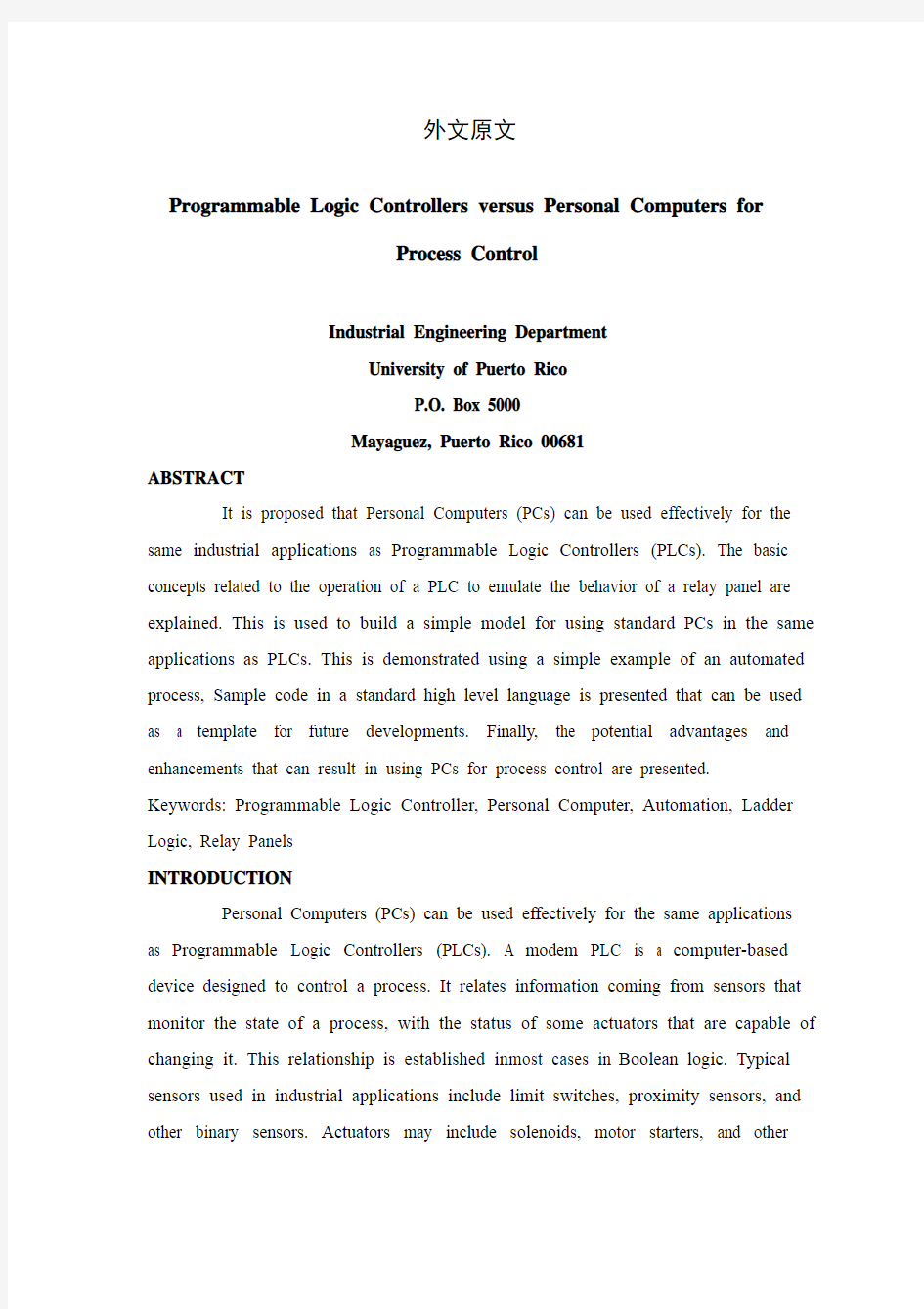
Personal Computers (PCs) can be used effectively for the same applications as Programmable Logic Controllers (PLCs). A modem PLC is a computer-based device designed to control a process. It relates information coming from sensors that monitor the state of a process, with the status of some actuators that are capable of changing it. This relationship is established in most cases in Boolean logic. Typical sensors used in industrial applications include limit switches, proximity sensors, and other binary sensors. Actuators may include solenoids, motor starters, and other
similar devices. Figure 1shows a simplified model of an industrial application where a PLC might be used.
Fig. 1: Model of Simple Process
RELAY PANELS
PLCs wore designed to replace relay panels. These are custom made controllers dedicated to a particular application. They can be expensive for complex systems, cannot be easily reconfigured, are difficult to troubleshoot, consume lots of energy, have a relatively moderate speed of operation, and have low reliability. Relay panels are not the most suitable alternative for a moderate to complex industrial application where flexibility, ease of maintenance and troubleshooting are very important. On the other hand, they are relatively low-tech and are easy to understand by electricians and non-engineering personnel.
The electrical control circuits of relay panels are generally drawn using so-called electric ladder diagrams. They differ slightly from conventional wiring diagrams in that they do not show the physical arrangement of the components, but emphasize the function of each circuit. They are a set of parallel circuits that in essence represent a hardwired program that controls the sequence of operations in a given process. Being electrical circuits in parallel gives the advantage of solving all the control logic simultaneously and practically instantaneously. Figure 2 represents an electric ladder diagram for a relay panel that can be used to control the process presented in fig. 1.
Fig. 2: Electric Ladder Diagram
PLCs are typically computer-based, solid-state, single-processor devices that emulate the behavior of an electric ladder diagram. Since they are sequential machines, to emulate the workings of parallel circuits that respond instantaneously, PLCs use an input/output image table and a scanning cycle.
An input/output image table is a memory structure that stores all the relevant information about the current scanning cycle. It can be subdivided in three basic parts: the input table, the output table, and the internal relay table, The current state of the inputs (sensors) is kept in the input table; the desired state of the outputs (actuators) is kept in the output table; and the state of the virtual control relays is kept in the internal relay table.
When a program is being nm in a PLC it is continuously executing a scanning cycle (fig. 3). The scanning cycle has two major parts (in an actual PLC it has other parts but two are relevant here for the sake of the discussion): the input/output scan, and the program scan. In the input/output scan the current state of the inputs is read from the input points and stored in the input table, and the desired state of the
Fig. 3: PLC Scanning Cycle
outputs (from the output table) is sent to the output points. The program scan solves the Boolean logic that relates the information in the input table, with that in the output and internal relay tables. Also, the information in the output and internal relay tables is updated during the program scan. In a PLC this Boolean logic is typically represented in a graphical language that looks very much like the electrical circuit that it emulates. This language is known as ladder logic. In fig. 4 there is a ladder logic program that can be used to control the process in fig. 1. Note the similarities with the electric ladder diagram in fig. 2. The advantage of the PLC scanning cycle scheme is that it allows multiple princesses to be controlled concurrently as in a relay panel.
Fig, 4: PLC Ladder Logic
PLCs overcome all of the relay panel shortcomings and currently are the most widely used industrial automation controllers. At the time of their introduction they were very successful because their language, ladder logic, was based tm electric
ladder diagrams which engineers and electricians of the time were already familiar with. Nevertheless, PLCs have some shortcomings of their own that are evident when compared with other available technology. Some of the most limiting ones include: them is no industry-standard hardware or software platform, they may limit the programmer as to the control actions and manipulations that can be made, and offer relatively low computing power for the money.
PERSONAL COMPUTERS
Another technology that could be used for the same purpose is the standard personal computer (PC). The PC is becoming increasingly popular for process control.
A PC-based controller model is proposed here which could replace PLCs in any industrial control application and would open up a world of possibilities in software development, standard components, and connectivity in general. This medal includes an industry-standard PC running any modem operating system, a set of standard input/output modules equivalent to those found in a typical PLC, and an application developed in any high level programming language which will implement a PLC scanning cycle.
A SIMPLE EXAMPLE
The proposed model will be presented through a sample program coded in Turbo Pascal~ for the control of the process shown in fig. 1. Assume that sensors are connected to the PC through input port hex address 3BD, and that actuators are connected to output port hen address 3BC, as shown in figs. 5 and 6 respectively.
Fig. 5: Input Connections
Fig. 6: Output Connections
The sample Pascal program is shown in fig. 7. The image tables: input, output, and internal relays, are implemented using Pascal Boolean variables. When any of these variables is TRUE, that represents an ON state; and whoa they are FALSE that represents an OFF state. When exchanging signals with the input and output points an ON state is represented by a logical "0" and an OFF state with a logical "1".
The main program is an emulation of the PLC scanning cycle presented in fig. 3. In this simplified example it is assumed that the PLC will be running its program until a key is pressed on the PC keyboard. Other device can be used if it is desired to use the PC keyboard for other more productive purpose.
The input/output scan is emulated using subroutine I_ O_Scan. There, the 8 bit input port (fig. 5) is read and the status of the individual bits stored in the input table. Also the status of the output points from the output table is written to the 8 bit output port (see fig. 6). The Program _Scan subroutine is a direct translation of the ladder diagram in fig. 4. For every rung in the ladder logic there is an if-then-else statement. The Initialize and Finalize subroutines worn added to handle the state of the output points and internal relays during the startup and shutdown of the PLC program
.
Fig.7:Sample Pascal Program
It should be noted that this is a very simplified example whose purpose is to provide a framework for control program development on a PC combining the programming paradigms of standard procedural high-level languages with the familiar PLC ladder logic. Although it cannot be fully demonstrated in this paper, it provides a simple way of simultaneous control of parallel processes without considering the intricacies of a particular operating system. It demonstrates that complex custom software does not have to be created to make this technology work.
The proposed model would be very easy to adapt and implement even in-house because it can still use ladder logic, so no new technological skills are necessary. Any typical PLC instructions can be added to the model very easily, including timers, counters, one-shots, and so on. Other custom PLC instructions suited to a particular application can be included that use the features of high level languages, making it more powerful than standard PLC ladder logic.
ADV ANTAGES OF PERSONAL COMPUTERS
The PC is a standard hardware/software platform. PCs improve at a rapid pace, become cheaper, and have mom power than PLCs. Pentium systems widely available today outperform even the fastest margins of 20:1 or more. A new
generation of PCs becomes available every six to nine months. By contrast new generation of PLC hardware becomes available every two to three years. PCs with at least 16Mbytes are commonplace, while PLCs still have memory in the order of Kbytes. The PC supports more standard peripherals available from many vendors such as CD ROM drives, sound cards, voles recognition, networking facilities, and so on. at very affordable prices. The PC is available worldwide, on short notice, from many vendors;
It has been envisioned that the next generation industrial controls should provide an open architecture and a single software development environment. The trend will be to move away from closed, proprietary systems due to the advantages an open architecture provides. It gives more flexibility since users do have to "marry" to a particular supplier. There is easier access to the latest technology since numerous independent developers are continuously advancing the functionality and ease of use of PC-compatible hardware and software. Also, it provides cost effectiveness because its largo market ensures a competitive environment and economies of scale that drive prices to their lowest level.
The PC can provide a totally integrated solution that incorporates the functions of the PLC, the man-machine interface, and the programming terminal. It can provide process simulation/emulation so that complete software development can be done independent of the hardware. Also, it can provide sophisticated troubleshooting and diagnostic tools, providing in-depth analysis of the state of the machine, possible causes for malfunction, and recommended remedies. You can even run off-the-shelf Windows software for data analysis while the control system is running. Standard Windows data exchange methods can be readily applied to move information between the control system and the rest of the enterprise.
PCs for industrial control might be successful today for reasons analogous to those for the PLCs at the time of their introduction; engineers today are well versed in computer programming and technology. Many sites already have significant PC programming expertise on hand. Also, the typical PC language paradigms lend themselves more readily to flowcharting techniques and languages of recent
development for control programming, such as Sequential Function Charts.
DISADV ANTAGES OF PERSONAL COMPUTERS
Commercial-grade PCs are not normally designed to tolerate the shock, vibration, temperature, and electrical noise frequently found on the manufacturing floor~:1. Even though hardware that meets these environmental conditions is readily available as both PLCs and PCs, this may increase the cost of implementing PC-based control. PCs may not be cost effective for applications with few I/O points (90% of the market). Very cheap PLCs are available for that market. PCs are visualized as solutions for more complex systems with many I/O points and complex control strategies. PC-based input/output interfacing may be as expensive, and more difficult to implement than that for PLCs141. PLCs are faster to restart after a power failure. They also have better ability to retain data so they are easier to restart from where they left off.
中文翻译
可编程序控制器与个人计算机在过程控制中的对比
工业工程部门
波多里哥大学
P .O . 信箱5000
Mayaguez, 波多里哥00681
摘要
有人提议,个人计算机(PCs) 和可编程序的逻辑控制器(PLCs )一样,能有效地使用在工业应用上。与PLC 的使用有关的基本概念可由继电控制板的动作来解释。这使基于标准个人计算机建立一个简单的模型,能和基于PLC的一样。本文列举了一个使用自动化过程的简单的例子,样品代码会由一种标准高级语言提出,这种高级语言可能被用作为模板。最后,提出了使用个人计算机做过程控制的潜在的好处和一些改进措施。
主题词:可编程序控制器, 个人计算机, 自动化, 梯形图, 继电控制板
介绍
个人计算机(个人计算机) 和可编程序的逻辑控制器(PLCs) 一样,可能有效地被用应用。现代PLC 控制过程,是以计算机为基础的。它的关系信息来自监测过程状态的传感器,是能改变它一些传动装置的状态。这个关系被建立在布尔逻辑的情况下。典型的工业中应用的传感器包括限位开关,邻近传感器,及二进制传感器。传动装置可能包括螺线管,马达起始者,和一些其它相关的设备。图1显示了一种工业应用的一个简化的模型,该模型中 PLC 得到应用。
图1 简化的过程模型
PLC替换继电控制板。这些定制的控制器致力于一种特殊应用。因为复杂系统,它们的造价高,很难重新构造,出现故障也不容易发现,消耗许多能量,适当的操作速度,和低可靠性。在要求维护灵活、方便,而且又要快速查明故障的复杂工业应用中,继电控制板不是最适当的选择。另一方面,他们相对地易学,容易被电工和非工程学人员了解。继电控制板电子控制电路一般使用梯形图。它们与常规接线图小小的不同是他们不显示组分的物理安排,但强调各条电路的作用。他们实质上代表一个被硬联线的节目控制操作,序列在一个指定的过程中的一套并联电路。电子电路的平行设计为解决所有控制逻辑带来好处,可以同时和瞬间动作。图2 代表一张梯形图,可以控制如图1 所示的工业过程。
图2 梯形图
PLC是典型地计算机为主的,不用真空管的,与梯形图的动作一致的唯一处理器设备。因为他们是连续机器,实时地反应并联电路的工作,PLC使用输入/输出表和扫描周期。
输入/输出表是一种记忆结构,它存储关于当前的扫描周期的所有的相关的信息。它被细分为三种基本的部分:输入表,输出表,和内部继电表,输入(传感器的)状态被保留在输入表;输出(传动装置)期待状态被保留在输出表;真正控制继电器的状态被保留在内部继电表中。
图3 PLC扫描周期
当程序是在PLC中运行,它连续的执行扫描周期(图 3)。扫描周期有二大部分(在实际PLC中,它有其它部分,这里只讨论相关的):输入扫描和程序扫描。在输入程序扫描输入的状态,从输入点和被存放的输入表中读入,并且程序的期待状态(从输出表)送到输出点。程序扫描解决布尔逻辑,它关系到在输入表的信息,在输出和内部继电表的信息。而且,信息在输出和内部继电表在程序扫描期间更新。在PLC 中这种布尔逻辑典型地代表图形语言,这种图形语言看起来像它仿真的电子电路。人所皆知,这种语言为梯形逻辑语言。图4的梯形逻辑程序可能使用在图1的控制过程中。注意,在图 2中相似的电子梯形图。PLC 扫描周期的好处是,在继电控制板中,它允许广泛的过程一致地被控制。
图4 PLC梯形逻辑
PLC能克服所有继电控制板缺点,目前是被广泛应用的工业自动化控制器。因为它们的语言,在它们的介绍之时它们是非常成功的,梯形逻辑,是电子工程师和梯形图编程人员已经通晓的电子梯形图。然而,显然PLC与其它可利用的技术比较,也有它们自己的一些缺点。它的局限有:它们是没有工业标准的硬件或软件平台,它们会限制程序员做的控制活动和操作,并且为了降低成本,它的计算能力相对低。
个人计算机
标准个人计算机(个人计算机) ,一种为达到同样目的的其它技术。它变得越来越普遍。在任一种工业控制应用中,一个基于个人计算机的控制器模型能替换PLC。可能会在软件开发领域会开辟一个世界,因为它的标准组分和连通性。这个模型包括一台能运行在任一个现代开放操作系统的标准个人计算机, 一套等效于典型的PLC中的输入模块的标准输入产品模块, 还有用于实施一个PLC 扫描周期的任一种高级编程语言。
一个简单的例子
提出的模型将通过一个抽样程序被编码在Turbo Pascal ,作为过程的控制,如图1所示. 假设, 传感器通过输入端十六进制地址3BD被连接到个人计算机, 并且, 传动装置被连接到输出端口十六进制地址3BC,地址分配如图 5 、图6所示。
图5 输入连接
图6 输出连接
样品Pascal程序如图 7所示。图像表:输入,输出,和继电表,使用Pascal布尔变量。当这些变量是真的,那代表开状态;而当他们是假的,代表关状态。当交换信号以输入和输出指向开状态代表一逻辑"0" 而关状态代表一逻辑"1" 。
图7 程序示例
注意,这是一个非常简化的例子,目的是为熟悉的PLC梯形逻辑的控制程序提供框架,以使个人计算机结合标准程序高级语言编程。虽然在本文里,没有做充分的说明,但是它提供平行的过程,没有考虑一个特殊操作系统的复杂,而且控制一个简单的方式。这说明,复杂的自定义软件不一定要做这项技术工作。
提出的模型非常容易适应和实施,因为它仍然使用梯形逻辑,那么就不一定要新技术。所有典型的PLC 指示可以非常容易地增加到模型,包括定时器,计数器等等。其它的适合于特殊应用的PLC可能包括使用高级语言,这又使它比标准PLC 梯形逻辑强有力。
个人计算机的优点
个人计算机是标准硬件软件平台。个人计算机以快速步伐改善,变得更加便宜,并且比PLC有更多力量。在奔腾系统广泛利用的今天,个人计算机胜过最快速的PLC 近20:1甚至更多。每六个到九个月,个人计算机就更新换代。相反每二到三年PLC 硬件更新一次。至少的在个人计算机中,16Mbytes是普遍的, 同
时PLC仍然的记忆区是按Kbyte 的顺序。个人计算机支持更加标准的外围设备,譬如大容量只读存储器驱动器,声卡,鼠标,网络设施,等等,可从许多贩卖者以合适的价格买到。通过许多贩卖者,个人计算机是在短时间内在全世界广泛使用。
有人构想,下一代工业控制应该提供一个开放式体系结构和一个唯一软件开发环境。趋向将是走出封闭,专有系统依赖一个开放式体系结构提供的好处。用户必须和一个特殊供应商"结婚" ,这提供了更多的灵活性。,因为许多独立开发商连续推进个人计算机,这些计算机兼容硬件和软件的功能,且易用,这使得对新的技术的掌握变的更加的容易,因为计算机的巨大的市场,它提供一个竞争环境,而且经济的原因驱使厂商们将价格压到最低,因此成本效率高。
个人计算机可能提供合并PLC的一种完全解决方案,基于人机接口和编程的终端。它能提供过程模仿,使得不依靠硬件的软件开发变成可能。并且,它能提供老练的查明故障和诊断器械的功能,提供对机器的状态的详细分析,可能的故障起因,并且推荐补救措施。当控制系统运行时,你能使用现成的窗口软件进行数据分析。控制系统和企业的其他部门之间传递信息使用标准窗口数据交换方法。
现在,个人计算机在工业控制中是成功的,其原因类似于那些PLC,今天工程师能很好的熟练的在计算机中编程并且应用。许多站已经有专业的个人计算机编程的技术在手。并且,典型的个人计算机语言范例易于使用流程图编制技术和流程表新发展技术对控制编程,譬如连续函数图。
商用的个人计算机通常没设计抗干扰、振动、温度和制造业中常发生的电子噪声。在PLC和个人计算机中的,应该用能适应这些环境状况的硬件,这也许会增加基于个人计算机的控制的费用。个人计算机以其少数I/O接点,不能在应用中有效的控制成本。因此非常便宜的PLC能占领市场(90%的市场)。对于有许多I/O 点和复杂控制策略的控制系统,个人计算机可以形象地给出解答。基于个人计算机的输入/输出接口装置是昂贵的,而且比那些基于PLC的装置更难应用。PLC可以快速地在电源故障以后重新开始。并且它们能准确的保留先前的数据,因此PLC更加容易重新从它们停止的地方开始。
控制系统基础论文中英文资料外文翻译文献 文献翻译 原文: Numerical Control One of the most fundamental concepts in the area of advanced manufacturing technologies is numerical control (NC).Prior to the advent of NC, all machine tools were manual operated and controlled. Among the many limitations associated with manual control machine tools, perhaps none is more prominent than the limitation of operator skills. With manual control, the quality of the product is directly related to and limited to the skills of the operator . Numerical control represents the first major step away from human control of machine tools. Numerical control means the control of machine tools and other manufacturing systems though the use of prerecorded, written symbolic instructions. Rather than operating a machine tool, an NC technician writes a program that issues operational instructions to the machine tool, For a machine tool to be numerically controlled , it must be interfaced with a device for accepting and decoding the p2ogrammed instructions, known as a reader. Numerical control was developed to overcome the limitation of human operator , and it has done so . Numerical control machines are more accurate than manually operated machines , they can produce parts more uniformly , they are faster, and the long-run tooling costs are lower . The development of NC led to the development of several other innovations in manufacturing technology: 1.Electrical discharge machining. https://www.doczj.com/doc/778791105.html,ser cutting. 3.Electron beam welding.
外文翻译 原文:The open system merit of Computer Numerical Control The open system merit is the system simple, the cost low, but the shortcoming is the precision is low. The reverse gap, the guide screw pitch error, stop inferiorly can affect the pointing accuracy by mistake. Following several kind of improvements measure may cause the pointing accuracy distinct improvement. 1. reverse gap error compensates The numerical control engine bed processing cutting tool and the work piece relative motion is depends upon the drive impetus gear,the guide screw rotation, thus the impetus work floor and so on moves the part to produce moves realizes. As traditional part gear, guide screw although the manufacture precision is very high, but always unavoidably has the gap. As a result of this kind of gap existence, when movement direction change, starts the section time to be able to cause inevitably actuates the part wasting time, appears the instruction pulse to push the motionless functional element the aspect. This has affected the engine bed processing precision, namely the instruction pulse and actual enters for the step does not tally,has the processing error therefore, the split-ring numerical control system all establishes generally has the reverse gap error compensatory function, with by makes up which wastes time the step reverse gap difference compensates is first actual reverse enters for the error, converts the pulse equivalent number it, compensates the subroutine as the gap the output, when the computer judgment appears when instruction for counter motion, transfers the gap to compensate the subroutine immediately, compensates the pulse after the output to eliminate the reverse gap to carry on again normally inserts makes up the movement. 2. often the value systematic characteristic position error compensates A kind of storehouse by transfers for the designer. Like this in the components design stage, the designer only must input the characteristic the parameter, the system direct production characteristic example model: We must save the related characteristic class in the database the structure information, the database table collection are use in saving this part of related information. According to the characteristic type definition need, we defined the characteristic class code table, the
Programmable logic controller A programmable logic controller (PLC) or programmable controller is a digital computer used for automation of electromechanical processes, such as control of machinery on factory assembly lines, amusement rides, or lighting fixtures. PLCs are used in many industries and machines. Unlike general-purpose computers, the PLC is designed for multiple inputs and output arrangements, extended temperature ranges, immunity to electrical noise, and resistance to vibration and impact. Programs to control machine operation are typically stored in battery-backed or non-volatile memory. A PLC is an example of a real time system since output results must be produced in response to input conditions within a bounded time, otherwise unintended operation will result. 1.History The PLC was invented in response to the needs of the American automotive manufacturing industry. Programmable logic controllers were initially adopted by the automotive industry where software revision replaced the re-wiring of hard-wired control panels when production models changed. Before the PLC, control, sequencing, and safety interlock logic for manufacturing automobiles was accomplished using hundreds or thousands of relays, cam timers, and drum sequencers and dedicated closed-loop controllers. The process for updating such facilities for the yearly model change-over was very time consuming and expensive, as electricians needed to individually rewire each and every relay. In 1968 GM Hydramatic (the automatic transmission division of General Motors) issued a request for proposal for an electronic replacement for hard-wired relay systems. The winning proposal came from Bedford Associates of Bedford, Massachusetts. The first PLC, designated the 084 because it was Bedford Associates' eighty-fourth project, was the result. Bedford Associates started a new company dedicated to developing, manufacturing, selling, and servicing this new product: Modicon, which stood for MOdular DIgital CONtroller. One of the people who worked on that project was Dick Morley, who is considered to be the "father" of the PLC. The Modicon brand was sold in 1977 to Gould Electronics, and later acquired by German Company AEG and then by French Schneider Electric, the current owner. One of the very first 084 models built is now on display at Modicon's headquarters in North Andover, Massachusetts. It was presented to Modicon by GM, when the unit was retired after nearly twenty years of uninterrupted service. Modicon used the 84
毕业设计(论文)外文资料翻译 学院:机械工程学院 专业:机械设计制造及其自动化 姓名: 学号:XXXXXXXXXX 外文出处:《Computational Intelligence and (用外文写)Design》 附件: 1.外文资料翻译译文;2.外文原文。 注:请将该封面与附件装订成册。
附件1:外文资料翻译译文 基于微型计算机的步进电机控制系统设计 孟天星余兰兰 山东理工大学电子与电气工程学院 山东省淄博市 摘要 本文详细地介绍了一种以AT89C51为核心的步进电机控制系统。该系统设计包括硬件设计、软件设计和电路设计。电路设计模块包括键盘输入模块、LED显示模块、发光二极管状态显示和报警模块。按键可以输入设定步进电机的启停、转速、转向,改变转速、转向等的状态参数。通过键盘输入的状态参数来控制步进电机的步进位置和步进速度进而驱动负载执行预订的工作。运用显示电路来显示步进电机的输入数据和运行状态。AT89C51单片机通过指令系统和编译程序来执行软件部分。通过反馈检测模块,该系统可以很好地完成上述功能。 关键词:步进电机,AT89C51单片机,驱动器,速度控制 1概述 步进电机因为具有较高的精度而被广泛地应用于运动控制系统,例如机器人、打印机、软盘驱动机、绘图仪、机械式阀体等等。过去传统的步进电机控制电路和驱动电路设计方法通常都极为复杂,由成本很高而且实用性很差的电器元件组成。结合微型计算机技术和软件编程技术的设计方法成功地避免了设计大量复杂的电路,降低了使用元件的成本,使步进电机的应用更广泛更灵活。本文步进电机控制系统是基于AT89C51单片机进行设计的,它具有电路简单、结构紧凑的特点,能进行加减速,转向和角度控制。它仅仅需要修改控制程序就可以对各种不同型号的步进电机进行控制而不需要改变硬件电路,所以它具有很广泛的应用领域。 2设计方案 该系统以AT89C51单片机为核心来控制步进电机。电路设计包括键盘输入电路、LED显示电路、发光二极管显示电路和报警电路,系统原理框图如图1所示。 At89c51单片机的P2口输出控制步进电机速度的时钟脉冲信号和控制步进电机运转方向的高低电平。通过定时程序和延时程序可以控制步进电机的速度和在某一
译文 流体传动及控制技术已经成为工业自动化的重要技术,是机电一体化技术的核心组成之一。而电液比例控制是该门技术中最具生命力的一个分支。比例元件对介质清洁度要求不高,价廉,所提供的静、动态响应能够满足大部分工业领域的使用要求,在某些方面已经毫不逊色于伺服阀。比例控制技术具有广阔的工业应用前景。但目前在实际工程应用中使用电液比例阀构建闭环控制系统的还不多,其设计理论不够完善,有待进一步的探索,因此,对这种比例闭环控制系统的研究有重要的理论价值和实践意义。本论文以铜电解自动生产线中的主要设备——铣耳机作为研究对象,在分析铣耳机组各构成部件的基础上,首先重点分析了铣耳机的关键零件——铣刀的几何参数、结构及切削性能,并进行了实验。用电液比例方向节流阀、减压阀、直流直线测速传感器等元件设计了电液比例闭环速度控制系统,对铣耳机纵向进给装置的速度进行控制。论文对多个液压阀的复合作用作了理论上的深入分析,着重建立了带压差补偿型的电液比例闭环速度控制系统的数学模型,利用计算机工程软件,研究分析了系统及各个组成环节的静、动态性能,设计了合理的校正器,使设计系统性能更好地满足实际生产需要 水池拖车是做船舶性能试验的基本设备,其作用是拖曳船模或其他模型在试验水池中作匀速运动,以测量速度稳定后的船舶性能相关参数,达到预报和验证船型设计优劣的目的。由于拖车稳速精度直接影响到模型运动速度和试验结果的精度,因而必须配有高精度和抗扰性能良好的车速控制系统,以保证拖车运动的稳速精度。本文完成了对试验水池拖车全数字直流调速控制系统的设计和实现。本文对试验水池拖车工作原理进行了详细的介绍和分析,结合该控制系统性能指标要求,确定采用四台直流电机作为四台车轮的驱动电机。设计了电流环、转速环双闭环的直流调速控制方案,并且采用转矩主从控制模式有效的解决了拖车上四台直流驱动电机理论上的速度同步和负载平衡等问题。由于拖车要经常在轨道上做反复运动,拖动系统必须要采用可逆调速系统,论文中重点研究了逻辑无环流可逆调速系统。大型直流电机调速系统一般采用晶闸管整流技术来实现,本文给出了晶闸管整流装置和直流电机的数学模型,根据此模型分别完成了电流坏和转速环的设计和分析验证。针对该系统中的非线性、时变性和外界扰动等因素,本文将模糊控制和PI控制相结合,设计了模糊自整定PI控制器,并给出了模糊控制的查询表。本文在系统基本构成及工程实现中,介绍了西门子公司生产的SIMOREGDC Master 6RA70全数字直流调速装置,并设计了该调速装置的启动操作步骤及参数设置。完成了该系统的远程监控功能设计,大大方便和简化了对试验水池拖车的控制。对全数字直流调速控制系统进行了EMC设计,提高了系统的抗干扰能力。本文最后通过数字仿真得到了该系统在常规PI控制器和模糊自整定PI控制器下的控制效果,并给出了系统在现场调试运行时的试验结果波形。经过一段时间的试运行工作证明该系统工作良好,达到了预期的设计目的。 提升装置在工业中应用极为普遍,其动力机构多采用电液比例阀或电液伺服阀控制液压马达或液压缸,以阀控马达或阀控缸来实现上升、下降以及速度控制。电液比例控制和电液伺服控制投资成本较高,维护要求高,且提升过程中存在速度误差及抖动现象,影响了正常生产。为满足生产要求,提高生产效率,需要研究一种新的控制方法来解决这些不足。随着科学技术的飞速发展,计算机技术在液压领域中的应用促进了电液数字控制技术的产生和发展,也使液压元件的数字化成为液压技术发展的必然趋势。本文以铅电解残阳极洗涤生产线中的提升装置为研究
毕业论文(设计)外文翻译 题目:可编程逻辑控制器技术 系部名称:信息工程系专业班级: 学生姓名:学号: 指导教师:教师职称: 2014 年3 月XX 日
译文 可编程逻辑控制器技术 引言 PLC(可编程逻辑控制器)实际是一个工业控制系统(近来我们看到更多的是用处理器来取代微控制器),在软件和硬件都配备的条件下,适合应用于工业环境。PLC 的发明是相当必要的,它代替了传统的依靠由继电接触器电路来控制电机。PLC 的工作原理是根据它的输入信号和工作状态来确定输出。用户通常是通过软件或编程输入一个程序,来输出所需要的结果。 如图 8-1 所示,PLC 是由典型的黑色构件组成。特别需要注意的是它的输入和输出, 因为在这些模块上,工业环境会给 CPU 一个输入线,所以很有必要将 CPU 模块隔离以保护其免遭有害的影响。程序单元通常是用计算机来编写程序(一般是梯形图)。 1.1CPU 的中央处理单元 中央处理单元(CPU)是一个 PLC 的主控制器。一般 CPU 本身是一个微控制器。通常这些都是 8 位微控制器,如 8051 ,现在的这些是 16 位和 32 位微控制器。潜规则是,你会发现用在 PLC 控制器上的微控制器多数是由日本生产的日立和富士通,欧洲的西门子控制器,和美国的摩托罗拉微控制器。CPU 也负责通讯,与 PLC 控制器的其它部分相互联系,如程序执行,内存操作,监督输入和设置输出。PLC 控制器拥有复杂的程序用于内存检查,以确保 PLC 内存不被损坏(内存检查是为了安全原因而作出的)。一般来说,CPU 单元多数用来检查 PLC 控制器本身,所以有可能出现的错误很早就会被发现。你可以简单地看任何 PLC 控制器,查看错误信号在发光二极管上的种种指示形式。 1.2内存 系统内存(今天主要是在 FLASH 技术上实现)用于一台 PLC 的过程控制系统。除了 这个操作系统它还包含用户程序将梯形图翻译成二进制的形式。 FLASH 存储器的内容仅在 用户程序改变下可以改变。PLC 控制器较早被用来代替闪存,EPROM 存储器代替了那些只能依靠紫外线灯等擦除内存并依靠程序员来编程的 FLASH 存储器。在 FLASH 技术的作用下这个过程被大大的缩短了。重组程序内存通过程序中的串行通讯用于应用程序开发。使用内存被划分成多个具有特殊功能的模块。存储器某些部分用来存储输入状态和输出状态。一个 输入信号的实际状态是用 1 或0 存储在一个特定的存储位。每一个输入信号和输出信号在内存里都有一个位与之相对应。内存的其他部分用来存储用户程序中使用的变量以及变量的内容。例如,定时器的值和计数器的值都将被存储在这部分内存里。 1.3PLC 控制器的编程 PLC 控制器可以通过计算机(常用的方式)进行编程,还可以通过手动编程器(控制台)编程。这实际上意味着如果你有需要的编程软件那么每个 PLC 控制器都可以通过计算机进行编程。今天的传输计算机是非常适合在工厂对 PLC 控制器进行编程的。这对工业有着非常重要的意义。一旦系统被刷新,重新读取正确的程序到 PLC 就很重要。还可以定期检查 PLC 中的程序是否改变了。这有助于避免在工厂车间发生危险状况(部分汽车制造商建立了通信网络,定期检查项目中的 PLC 控制器,以确保执行的程序是正确的)。
英文原文 Introductions to Control Systems Automatic control has played a vital role in the advancement of engineering and science. In addition to its extreme importance in space-vehicle, missile-guidance, and aircraft-piloting systems, etc, automatic control has become an important and integral part of modern manufacturing and industrial processes. For example, automatic control is essential in such industrial operations as controlling pressure, temperature, humidity, viscosity, and flow in the process industries; tooling, handling, and assembling mechanical parts in the manufacturing industries, among many others. Since advances in the theory and practice of automatic control provide means for attaining optimal performance of dynamic systems, improve the quality and lower the cost of production, expand the production rate, relieve the drudgery of many routine, repetitive manual operations etc, most engineers and scientists must now have a good understanding of this field. The first significant work in automatic control was James Watt’s centrifugal governor for the speed control of a steam engine in the eighteenth century. Other significant works in the early stages of development of control theory were due to Minorsky, Hazen, and Nyquist, among many others. In 1922 Minorsky worked on automatic controllers for steering ships and showed how stability could be determined by the differential equations describing the system. In 1934 Hazen, who introduced the term “ervomechanisms”for position control systems, discussed design of relay servomechanisms capable of closely following a changing input. During the decade of the 1940’s, frequency-response methods made it possible for engineers to design linear feedback control systems that satisfied performance requirements. From the end of the 1940’s to early 1950’s, the root-locus method in control system design was fully developed. The frequency-response and the root-locus methods, which are the
1 Bit Logic In structi ons 1.1 Overview of Bit Logic In structi ons 1.1.1 Description Bit logic in structi ons work with two digits, 1 and 0. These two digits form the base of a nu mber system called the binary system. The two digits 1 and 0 are called binary digits or bits. In the world of con tacts and coils, a 1 in dicates activated or en ergized, and a 0 in dicates not activated or not en ergized. The bit logic in struct ions in terpret sig nal states of 1 and 0 and comb ine them accord ing to Boolea n logic. These comb in ati ons produce a result of 1 or 0 that is called the “result of logic operati on ” (RLO). The logic operations that are triggered by the bit logic instructions perform a variety of fun cti ons. There are bit logic in structio ns to perform the followi ng fun cti ons: ---| |--- Normally Ope n Co ntact (Address) ---| / |--- Normally Closed Con tact (Address) ---(SAVE) Save RLO into BR Memory XOR Bit Exclusive OR ---()Output Coil ---(# )--- Midli ne Output ---|NOT|--- In vert Power Flow The followi ng in structio ns react to an RLO of 1: ---(S ) Set Coil ---(R ) Reset Coil SR Set-Reset Flip Flop RS Reset-Set Flip Flop Other in structi ons react to a positive or n egative edge tran siti on to perform the followi ng functions: ---(N)--- Negative RLO Edge Detectio n ---(P)--- Positive RLO Edge Detectio n NEG Address Negative Edge Detectio n POS Address Positive Edge Detectio n
液位控制系统论文中英文资料对照外文翻译 The liquid level control system based on dde\matlab\simulink Process control is an important application field of automatic technology, it is to point to the level, temperature, flow control process variables, such as in metallurgy, machinery, chemical, electric power, etc can be widely used. Especially liquid level control technology in real life, played an important role in production, for example, the water supply, civil water tower if low water levels, can affect people's lives in water; Industrial enterprises with water, if the drainage water drainage or controlled properly or not, in relation to the workshop of condition; Boiler drum, if the control level boiler is too low, can make level boiler overheating, possible accident; Jing flow, liquid level control tower control accuracy and level of the craft can influence the quality of the products and the cost, etc. In these production field, are basically labor strength or the operation has certain risk nature of work, extremely prone to accidents caused by operating error, the losses, killing manufacturer. Visible, in actual production, liquid level control accuracy and control effects directly affect the factory production cost and economic benefit of safety coefficient. Even equipment So, in order to ensure safety, convenient operation, you have to research the development of a d v a n c e d l e v e l c o n t r o l m e t h o d s a n d s t r a t e g i e s. The graduation design topic is the liquid level control system based on dde\matlab\simulink\force control, Among them was controlled object for tank level, Communication mode for DDE communications , Matlab is mainly used in the simulation test ,And force control software used for modeling, This system mainly through combination of hardware and software device to achieve precise control of liquid level , In modern industry level control of important component, it influence upon production not allow to ignore, in order to ensure safety in production and the product quality and quantity, the level and perform effective control is very necessary, The following is a description of all aspects:
1 Bit Logic Instructions 1.1 Overview of Bit Logic Instructions 1.1.1 Description Bit logic instructions work with two digits, 1 and 0. These two digits form the base of a number system called the binary system. The two digits 1 and 0 are called binary digits or bits. In the world of contacts and coils, a 1 indicates activated or energized, and a 0 indicates not activated or not energized. The bit logic instructions interpret signal states of 1 and 0 and combine them according to Boolean logic. These combinations produce a result of 1 or 0 that is called the “result of logic operation” (RLO). The logic operations that are triggered by the bit logic instructions perform a variety of functions. There are bit logic instructions to perform the following functions: ---| |--- Normally Open Contact (Address) ---| / |--- Normally Closed Contact (Address) ---(SAVE) Save RLO into BR Memory XOR Bit Exclusive OR ---( ) Output Coil ---( # )--- Midline Output ---|NOT|--- Invert Power Flow The following instructions react to an RLO of 1: ---( S ) Set Coil ---( R ) Reset Coil SR Set-Reset Flip Flop RS Reset-Set Flip Flop Other instructions react to a positive or negative edge transition to perform the following functions: ---(N)--- Negative RLO Edge Detection ---(P)--- Positive RLO Edge Detection NEG Address Negative Edge Detection POS Address Positive Edge Detection
外文文献: Design and Implementation of Heat Exchange Station Control System Keywords:Heat exchange station, Control system, PLC, Inverter, Configuration software. Abstract.This paper introduces a design and implementation of heat exchange station control system based on PLC and industrial configuration software, which includes the contr ol scheme and principle, hardware selection and software design, etc. The circulating pumps and re plenishing pumps in the system can all be driven automatically by PLC and inverter. Main process parameters, such as steam pressure and measurement temperature and so on,can all be shown on the industrial PC running configuration software, and instructions could be sent by the engineer and operator on-the-spot via the Human Machine Interface as well. The automatic pressures adjustment of stea m supply of the heater by advanced PID algorithm has been realized finally. It is verified that the system is highly reliable and stable, and it greatly enhances the level of automation and pressure control accuracy of the heat exchange station and meets all the equipments running demands well. Introduction With the rapid development of economy and society, heat supply systems are the key power source in the communities and plants in China. As a media between heat sources and heat loads in the systems, a heat exchange stations plays a very important role for the heat supply quality. Traditionally, most of the pumps in the heat supply systems are operated by valves manually, s o it could bring about the power energy consuming, high labor intensity and low operation automation. I n this paper a design of control system for heat exchange station based on PLC, inverter and indust rial configuration software was proposed,accordingly the aim for power energy saving,hi