英文资料
TRANSFORMER
1. INTRODUCTION
The high-voltage transmission was need for the case electrical power is to be provided at considerable distance from a generating station. At some point this high voltage must be reduced, because ultimately is must supply a load. The transformer makes it possible for various parts of a power system to operate at different voltage levels. In this paper we discuss power transformer principles and applications.
2. TOW-WINDING TRANSFORMERS
A transformer in its simplest form consists of two stationary coils coupled by a mutual magnetic flux. The coils are said to be mutually coupled because they link a common flux.
In power applications, laminated steel core transformers (to which this paper is restricted) are used. Transformers are efficient because the rotational losses normally associated with rotating machine are absent, so relatively little power is lost when transforming power from one voltage level to another. Typical efficiencies are in the range 92 to 99%, the higher values applying to the larger power transformers.
The current flowing in the coil connected to the ac source is called the primary winding or simply the primary. It sets up the flux φ in the core, which varies periodically both in magnitude and direction. The flux links the second coil, called the secondary winding or simply secondary. The flux is changing; therefore, it induces a voltage in the secondary by electromagnetic induction in accordance with Lenz’s law. Thus the primary receives its power from the source while the secondary supplies this power to the load. This action is known as transformer action.
3. TRANSFORMER PRINCIPLES
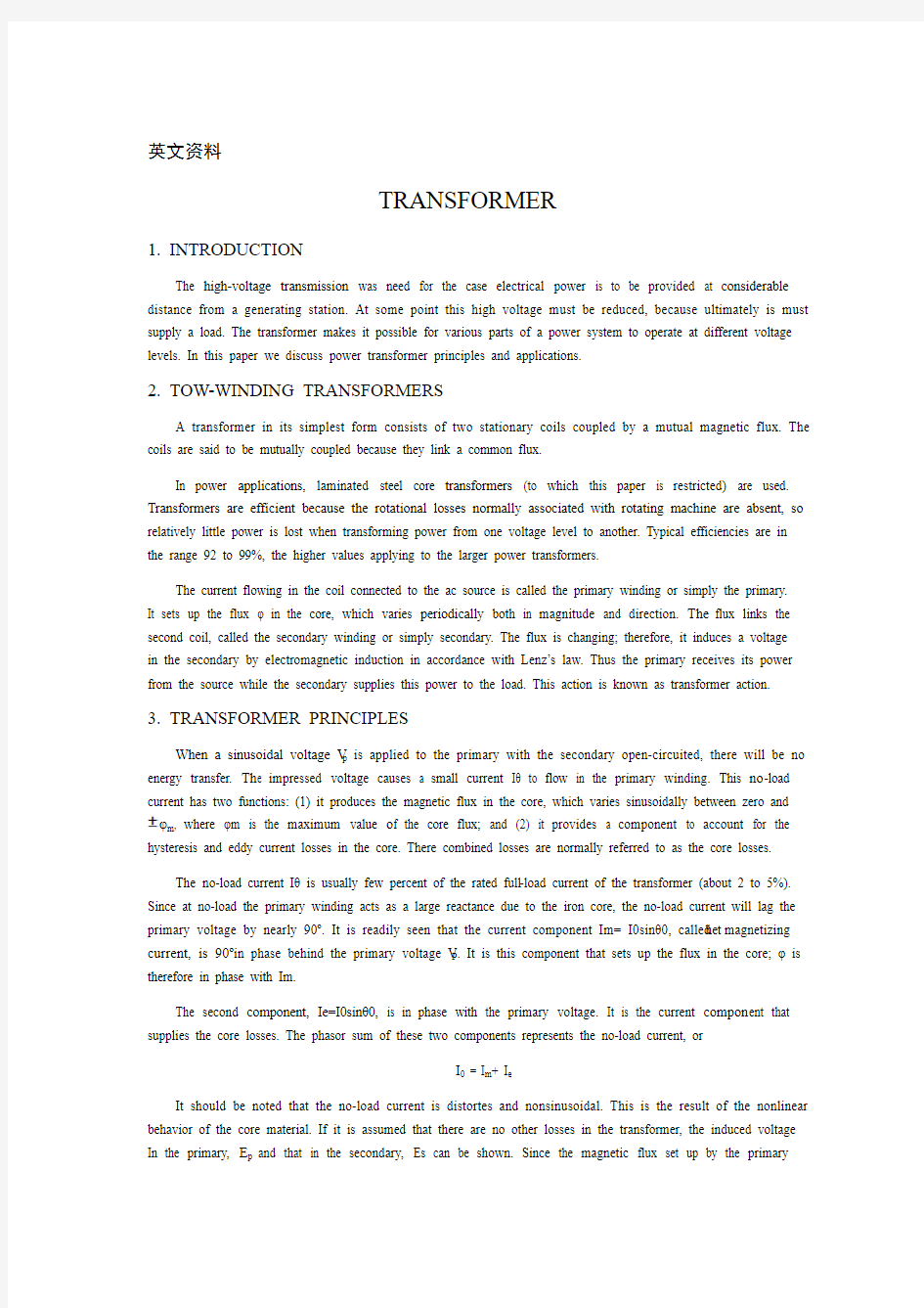
When a sinusoidal voltage V p is applied to the primary with the secondary open-circuited, there will be no energy transfer. Th e impressed voltage causes a small current Iθ to flow in the primary winding. This no-load current has two functions: (1) it produces the magnetic flux in the core, which varies sinusoidally between zero and φm, where φm is the maximum value o f the core flux; and (2) it provides a component to account for the hysteresis and eddy current losses in the core. There combined losses are normally referred to as the core losses.
The no-load current Iθ is usually few percent of the rated full-load current of the transformer (about 2 to 5%). Since at no-load the primary winding acts as a large reactance due to the iron core, the no-load current will lag the primary voltage by nearly 90o. It is readily seen that the current component Im= I0sinθ0, called t he magnetizing current, is 90o in phase behind the primary voltage V P. It is this component that sets up the flux in the core; φ is therefore in phase with Im.
The second component, Ie=I0sinθ0, is in phase with the primary voltage. It is the current compon ent that supplies the core losses. The phasor sum of these two components represents the no-load current, or
I0 = I m+ I e
It should be noted that the no-load current is distortes and nonsinusoidal. This is the result of the nonlinear behavior of the core material. If it is assumed that there are no other losses in the transformer, the induced voltage In the primary, E p and that in the secondary, Es can be shown. Since the magnetic flux set up by the primary
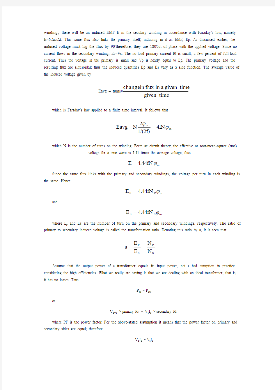
winding ,there will be an induced EMF E in the secon dary winding in accordance with Faraday’s law, namely, E=NΔφ/Δt. This same flux also links the primary itself, inducing in it an EMF, Ep. As discussed earlier, the induced voltage must lag the flux by 90o, therefore, they are 180o out of phase with the applied voltage. Since no current flows in the secondary winding, Es=Vs. The no-load primary current I0 is small, a few percent of full-load current. Thus the voltage in the primary is small and Vp is nearly equal to Ep. The primary voltage and the resulting flux are sinusoidal; thus the induced quantities Ep and Es vary as a sine function. The average value of the induced voltage given by Eavg = turns×given time
given time a in flux in change which is Faraday’s law applied to a finite time interval. It follows that
m m 4fN 1/(2f)
2N Eavg ??== which N is the number of turns on the winding. Form ac circuit theory, the effective or root-mean-square (rms)
voltage for a sine wave is 1.11 times the average voltage; thus
m 4.44fN E ?=
Since the same flux links with the primary and secondary windings, the voltage per turn in each winding is the same. Hence
m P P 4.44fN E ?=
and
m S S 4.44fN E ?=
where E p and Es are the number of turn on the primary and secondary windings, respectively. The ratio of primary to secondary induced voltage is called the transformation ratio. Denoting this ratio by a, it is seen that
S P S P N N E E a ==
Assume that the output power of a transformer equals its input power, not a bad sumption in practice considering the high efficiencies. What we really are saying is that we are dealing with an ideal transformer; that is, it has no losses. Thus
P m = P out
or
V p I p × primary PF = V s I s × secondary PF
where PF is the power factor. For the above-stated assumption it means that the power factor on primary and secondary sides are equal; therefore
V p I p = V s I s
from which is obtained
S P S P I I V V =≌S P E E ≌a
It shows that as an approximation the terminal voltage ratio equals the turns ratio. The primary and secondary current, on the other hand, are inversely related to the turns ratio. The turns ratio gives a measure of how much the secondary voltage is raised or lowered in relation to the primary voltage. To calculate the voltage regulation, we need more information.
The ratio of the terminal voltage varies somewhat depending on the load and its power factor. In practice, the transformation ratio is obtained from the nameplate data, which list the primary and secondary voltage under full-load condition.
When the secondary voltage Vs is reduced compared to the primary voltage, the transformation is said to be a step-down transformer: conversely, if this voltage is raised, it is called a step-up transformer. In a step-down transformer the transformation ratio a is greater than unity (a>1.0), while for a step-up transformer it is smaller than unity (a<1.0). In the event that a=1, the transformer secondary voltage equals the primary voltage. This is a special type of transformer used in instances where electrical isolation is required between the primary and secondary circuit while maintaining the same voltage level. Therefore, this transformer is generally knows as an isolation transformer.
As is apparent, it is the magnetic flux in the core that forms the connecting link between primary and secondary circuit. In section 4 it is shown how the primary winding current adjusts itself to the secondary load current when the transformer supplies a load.
Looking into the transformer terminals from the source, an impedance is seen which by definition equals Vp / Ip. From S P S P I I V V =≌S P E E ≌a, we have Vp = aVs and Ip = Is/a.In terms of Vs and Is the ratio of Vp to Ip is
s
s 2S S P P I V a /a I aV I V ==
But Vs / Is is the load impedance Z L thus we can say that
Z m (primary) = a 2Z L This equation tells us that when an impedance is connected to the secondary side, it appears from the source as an impedance having a magnitude that is a 2 times its actual value. We say that the load impedance is reflected or referred to the primary. It is this property of transformers that is used in impedance-matching applications.
4. TRANSFORMERS UNDER LOAD
The primary and secondary voltages shown have similar polarities, as indicated by the “dot-making ” convention. The dots near the upper ends of the windings have the same meaning as in circuit theory; the marked terminals have the same polarity. Thus when a load is connected to the secondary, the instantaneous load current is in the direction shown. In other words, the polarity markings signify that when positive current enters both windings at the marked terminals, the MMFs of the two windings add.
In general, it will be found that the transformer reacts almost instantaneously to keep the resultant core flux essentially constant. Moreover, the core flux φ0 drops very slightly between n o load and full load (about 1 to 3%), a necessary condition if Ep is to fall sufficiently to allow an increase in Ip.
On the primary side, Ip’ is the current that flows in the primary to balance the demagnetizing effect of Is. Its MMF N p I p’ sets up a flux linking the primary only. Since the core flux φ0 remains constant. I0 must be the same current that energizes the transformer at no load. The primary current Ip is therefore the sum of the current Ip’ and I0.
Because the no-load current is relatively small, it is correct to assume that the primary ampere-turns equal the secondary ampere-turns, since it is under this condition that the core flux is essentially constant. Thus we will assume that I0 is negligible, as it is only a small component of the full-load current.
When a current flows in the secondary winding, the resulting MMF (N s I s) creates a separate flux, apart from the flux φ0produced by I0, which links the secondary winding only. This flux does no link with the primary winding and is therefore not a mutual flux.
In addition, the load current that flows through the primary winding creates a flux that links with the primary winding only; it is called the primary leakage flux. The secondary- leakage flux gives rise to an induced voltage that is not counter balanced by an equivalent induced voltage in the primary. Similarly, the voltage induced in the primary is not counterbalanced in the secondary winding. Consequently, these two induced voltages behave like voltage drops, generally called leakage reactance voltage drops. Furthermore, each winding has some resistance, which produces a resistive voltage drop. When taken into account, these additional voltage drops would complete the equivalent circuit diagram of a practical transformer. Note that the magnetizing branch is shown in this circuit, which for our purposes will be disregarded. This follows our earlier assumption that the no-load current is assumed negligible in our calculations. This is further justified in that it is rarely necessary to predict transformer performance to such accuracies. Since the voltage drops are all directly proportional to the load current, it means that at no-load conditions there will be no voltage drops in either winding.
中文翻译
变压器
1. 介绍
要从远端发电厂送出电能,必须应用高压输电。因为最终的负荷,在一些点高电压必须降低。变压器能使电力系统各个部分运行在电压不同的等级。本文我们讨论的原则和电力变压器的应用。
2. 双绕组变压器
变压器的最简单形式包括两个磁通相互耦合的固定线圈。两个线圈之所以相互耦合,是因为它们连接着共同的磁通。
在电力应用中,使用层式铁芯变压器。变压器是高效率的,因为它没有旋转损失,因此在电压等级转换的过程中,能量损失比较少。典型的效率范围在92到99%,上限值适用于大功率变压器。
从交流电源流入电流的一侧被称为变压器的一次侧绕组或者是原边。它在铁圈中建立了磁通φ,它的幅值和方向都会发生周期性的变化。磁通连接的第二个绕组被称为变压器的二次侧绕组或者是副边。磁通是变化的;因此依据楞次定律,电磁感应在二次侧产生了电压。变压器在原边接收电能的同时也在向副边所带的负荷输送电能。这就是变压器的作用。
3. 变压器的工作原理
当二次侧电路开路是,即使原边被施以正弦电压Vp ,也是没有能量转移的。外加电压在一次侧绕组中产生一个小电流θI 。这个空载电流有两项功能:(1)在铁芯中产生电磁通,该磁通在零和m ?±之间做正弦变化,m ?是铁芯磁通的最大值;(2)它的一个分量说明了铁芯中的涡流和磁滞损耗。这两种相关的损耗被称为铁芯损耗。
变压器空载电流θI 一般大约只有满载电流的2%—5%。因为在空载时,原边绕组中的铁芯相当于一个很大的电抗,空载电流的相位大约将滞后于原边电压相位90o。显然可见电流分量00m sin θI I =,被称做励磁电流,它在相位上滞后于原边电压V P 90o。就是这个分量在铁芯中建立了磁通;因此磁通φ与m I 同相。
第二个分量Ie=I 0sinθ0,与原边电压同相。这个电流分量向铁芯提供用于损耗的电流。两个相量的分量和代表空载电流,即I 0= I m + I e
应注意的是空载电流是畸变和非正弦形的。这种情况是非线性铁芯材料造成的。 如果假定变压器中没有其他的电能损耗一次侧的感应电动势E p 和二次侧的感应电压E s 可以表示出来。因为一次侧绕组中的磁通会通过二次绕组,依据法拉第电磁感应定律,二次侧绕组中将产生一个电动势E ,即E=N Δφ/Δt 。相同的磁通会通过原边自身,产生一个电动势E p 。正如前文中讨论到的,所产生的电压必定滞后于磁通90o,因此,它于施加的电压有180o的相位差。因为没有电流流过二次侧绕组,E s =V s 。一次侧空载电流很小,仅为满载电流的百分之几。因此原边电压很小,并且Vp 的值近乎等于E p 。原边的电压和它产生的磁通波形是正弦形的;因此产生电动势E p 和E s 的值是做正弦变化的。产生电压的平均值如下
给定时间
给定时间内磁通变化量 turns Eavg ?= 即是法拉第定律在瞬时时间里的应用。它遵循
m m 4fN 1/(2f)
2N Eavg ??== 其中N 是指线圈的匝数。从交流电原理可知,有效值是一个正弦波,其值为
平均电压的1.11倍;因此
m 4.44fN E ?=
因为一次侧绕组和二次侧绕组的磁通相等,所以绕组中每匝的电压也相同。因此
m P P 4.44fN E ?=
并且
m S S 4.44fN E ?=
其中N p 和E s 是一次侧绕组和二次侧绕组的匝数。一次侧和二次侧电压增长的比率称做变比。用字母a 来表示这个比率,如下式
S
P S P N N E E a == 假设变压器输出电能等于其输入电能——这个假设适用于高效率的变压器。实际上我们是考虑一台理想状态下的变压器;这意味着它没有任何损耗。因此
P m = P out
或者
V p I p × primary PF = V s I s × secondary PF
这里PF 代表功率因素。在上面公式中一次侧和二次侧的功率因素是相等的;因此
V p I p = V s I s
从上式我们可以得知
S P S P I I V V =≌S
P E E ≌a 它表明端电压比等于匝数比,换句话说,一次侧和二次侧电流比与匝数比成反比。匝数比可以衡量二次侧电压相对于一次恻电压是升高或者是降低。为了计算电压,我们需要更多数据。
终端电压的比率变化有些根据负载和它的功率因素。实际上, 变比从标识牌数据获得, 列出在满载情况下原边和副边电压。
当副边电压V s 相对于原边电压减小时,这个变压器就叫做降压变压器。如果这个电压是升高的,它就是一个升压变压器。在一个降压变压器中传输变比a 远大于1(a>1.0),同样的,一个升压变压器的变比小于1(a<1.0)。当a=1时,变压器的二次侧电压就等于起一
次侧电压。这是一种特殊类型的变压器,可被应用于当一次侧和二次侧需要相互绝缘以维持相同的电压等级的状况下。因此,我们把这种类型的变压器称为绝缘型变压器。
显然,铁芯中的电磁通形成了连接原边和副边的回路。在第四部分我们会了解到当变压器带负荷运行时一次侧绕组电流是如何随着二次侧负荷电流变化而变化的。
从电源侧来看变压器,其阻抗可认为等于V p /I p 。从等式 S P S P I I V V =≌S
P E E ≌a 中我们可知V p = aV s 并且I p = I s /a 。根据V s 和I s ,可得V p 和I p 的比例是
s
s 2S S P P I V a /a I aV I V == 但是V s / I s 负荷阻抗Z L ,因此我们可以这样表示
Z m (primary) = a 2Z L
这个等式表明二次侧连接的阻抗折算到电源侧,其值为原来的a 2倍。我们把这种折算方式称为负载阻抗向一次侧的折算。这个公式应用于变压器的阻抗匹配。
4. 有载情况下的变压器
一次侧电压和二次侧电压有着相同的极性,一般习惯上用点记号表示。如果点号同在线圈的上端,就意味着它们的极性相同。因此当二次侧连接着一个负载时,在瞬间就有一个负荷电流沿着这个方向产生。换句话说,极性的标注可以表明当电流流过两侧的线圈时,线圈中的磁动势会增加。
总的来说,变压器为了保持磁通是常数,对磁通变化的响应是瞬时的。更重要的是,在空载和满载时,主磁通φ0的降落是很少的(一般在)1至3%。其需要的条件是E 降落很多来使电流I p 增加。
在一次侧,电流I p 、在一次侧流过以平衡I s 产生的影响。它的磁动势N p I p 、
只停留在一次侧。因为铁芯的磁通φ0保持不变,变压器空载时空载电流I 0必定会为其提供能量。故一次
侧电流I p 是电流I p 、与I 0、的和。
因为空载电流相对较小,那么一次侧的安匝数与二次侧的安匝数相等的假设是成立的。因为在这种状况下铁芯的磁通是恒定的。因此我们仍旧可以认定空载电流I 0相对于满载电流是极其小的。
当一个电流流过二次侧绕组,它的磁动势(N s I s )将产生一个磁通,于空载电流I 0产生的磁通φ0不同,它只停留在二次侧绕组中。因为这个磁通不流过一次侧绕组,所以它不是一个公共磁通。
另外,流过一次侧绕组的负载电流只在一次侧绕组中产生磁通,这个磁通被称为一次侧的漏磁。二次侧漏磁将使电压增大以保持两侧电压的平衡。一次侧漏磁也一样。因此,这两个增大的电压具有电压降的性质,总称为漏电抗电压降。另外,两侧绕组同样具有阻抗,这也将产生一个电阻压降。把这些附加的电压降也考虑在内,这样一个实际的变压器的等值电路图就完成了。由于分支励磁体现在电流里,为了分析我们可以将它忽略。这就符我们前面计算中可以忽略空载电流的假设。这证明了它对我们分析变压器时所产生的影响微乎其微。因为电压降与负载电流成比例关系,这就意味着空载情况下一次侧和二次侧绕组的电压降都为零。
中英文对照资料外文翻译文献 附件1:外文资料翻译译文 传感器新技术的发展 传感器是一种能将物理量、化学量、生物量等转换成电信号的器件。输出信号有不同形式,如电压、电流、频率、脉冲等,能满足信息传输、处理、记录、显示、控制要求,是自动检测系统和自动控制系统中不可缺少的元件。如果把计算机比作大脑,那么传感器则相当于五官,传感器能正确感受被测量并转换成相应输出量,对系统的质量起决定性作用。自动化程度越高,系统对传感器要求越高。在今天的信息时代里,信息产业包括信息采集、传输、处理三部分,即传感技术、通信技术、计算机技术。现代的计算机技术和通信技术由于超大规模集成电路的飞速发展,而已经充分发达后,不仅对传感器的精度、可靠性、响应速度、获取的信息量要求越来越高,还要求其成本低廉且使用方便。显然传统传感器因功能、特性、体积、成本等已难以满足而逐渐被淘汰。世界许多发达国家都在加快对传感器新技术的研究与开发,并且都已取得极大的突破。如今传感器新技术的发展,主要有以下几个方面: 利用物理现象、化学反应、生物效应作为传感器原理,所以研究发现新现象与新效应是传感器技术发展的重要工作,是研究开发新型传感器的基础。日本夏普公司利用超导技术研制成功高温超导磁性传感器,是传感器技术的重大突破,其灵敏度高,仅次于超导量子干涉器件。它的制造工艺远比超导量子干涉器件简单。可用于磁成像技术,有广泛推广价值。 利用抗体和抗原在电极表面上相遇复合时,会引起电极电位的变化,利用这一现象可制出免疫传感器。用这种抗体制成的免疫传感器可对某生物体内是否有这种抗原作检查。如用肝炎病毒抗体可检查某人是否患有肝炎,起到快速、准确作用。美国加州大学巳研制出这类传感器。 传感器材料是传感器技术的重要基础,由于材料科学进步,人们可制造出各种新型传感器。例如用高分子聚合物薄膜制成温度传感器;光导纤维能制成压力、流量、温度、位移等多种传感器;用陶瓷制成压力传感器。
中等分辨率制备分离的 快速色谱技术 W. Clark Still,* Michael K a h n , and Abhijit Mitra Departm(7nt o/ Chemistry, Columbia Uniuersity,1Veu York, Neu; York 10027 ReceiLied January 26, 1978 我们希望找到一种简单的吸附色谱技术用于有机化合物的常规净化。这种技术是适于传统的有机物大规模制备分离,该技术需使用长柱色谱法。尽管这种技术得到的效果非常好,但是其需要消耗大量的时间,并且由于频带拖尾经常出现低复原率。当分离的样本剂量大于1或者2g时,这些问题显得更加突出。近年来,几种制备系统已经进行了改进,能将分离时间减少到1-3h,并允许各成分的分辨率ΔR f≥(使用薄层色谱分析进行分析)。在这些方法中,在我们的实验室中,媒介压力色谱法1和短柱色谱法2是最成功的。最近,我们发现一种可以将分离速度大幅度提升的技术,可用于反应产物的常规提纯,我们将这种技术称为急骤色谱法。虽然这种技术的分辨率只是中等(ΔR f≥),而且构建这个系统花费非常低,并且能在10-15min内分离重量在的样本。4 急骤色谱法是以空气压力驱动的混合介质压力以及短柱色谱法为基础,专门针对快速分离,介质压力以及短柱色谱已经进行了优化。优化实验是在一组标准条件5下进行的,优化实验使用苯甲醇作为样本,放在一个20mm*5in.的硅胶柱60内,使用Tracor 970紫外检测器监测圆柱的输出。分辨率通过持续时间(r)和峰宽(w,w/2)的比率进行测定的(Figure 1),结果如图2-4所示,图2-4分别放映分辨率随着硅胶颗粒大小、洗脱液流速和样本大小的变化。
The smart grid Smart grid is the grid intelligent (electric power), also known as the "grid" 2.0, it is based on the integration, high-speed bidirectional communication network, on the basis of through the use of advanced sensor and measuring technology, advanced equipme nt technology, the advanced control method, and the application of advanced technology of decision support system, realize the power grid reliability, security, economic, efficient, environmental friendly and use the security target, its main features include self-healing, incentives and include user, against attacks, provide meet user requirements of power quality in the 21st century, allow all sorts of different power generation in the form of access, start the electric power market and asset optimizatio n run efficiently. The U.S. department of energy (doe) "the Grid of 2030" : a fully automated power transmission network, able to monitor and control each user and power Grid nodes, guarantee from power plants to end users among all the nodes in the whole process of transmission and distribution of information and energy bi-directional flow. China iot alliance between colleges: smart grid is made up of many parts, can be divided into:intelligent substation, intelligent power distribution network, intelli gent watt-hourmeter,intelligent interactive terminals, intelligent scheduling, smart appliances, intelligent building electricity, smart city power grid, smart power generation system, the new type of energy storage system.Now a part of it to do a simple i ntroduction. European technology BBS: an integration of all users connected to the power grid all the behavior of the power transmission network, to provide sustained and effective economic and security of power. Chinese academy of sciences, institute of electrical: smart grid is including all kinds of power generation equipment, power transmission and distribution network, power equipment and storage equipment, on the basis of the physical power grid will be modern advanced sensor measurement technology, network technology, communication
译自<<科技英语>> 变压器 1. 介绍 要从远端发电厂送出电能,必须应用高压输电。因为最终的负荷,在一些点高电压必须降低。变压器能使电力系统各个部分运行在电压不同的等级。本文我们讨论的原则和电力变压器的应用。 2. 双绕组变压器 变压器的最简单形式包括两个磁通相互耦合的固定线圈。两个线圈之所以相互耦合,是因为它们连接着共同的磁通。 在电力应用中,使用层式铁芯变压器(本文中提到的)。变压器是高效率的,因为它没有旋转损失,因此在电压等级转换的过程中,能量损失比较少。典型的效率范围在92到99%,上限值适用于大功率变压器。 从交流电源流入电流的一侧被称为变压器的一次侧绕组或者是原边。它在铁圈中建立了磁通φ,它的幅值和方向都会发生周期性的变化。磁通连接的第二个绕组被称为变压器的二次侧绕组或者是副边。磁通是变化的;因此依据楞次定律,电磁感应在二次侧产生了电压。变压器在原边接收电能的同时也在向副边所带的负荷输送电能。这就是变压器的作用。 3. 变压器的工作原理 当二次侧电路开路是,即使原边被施以正弦电压V p,也是没有能量转移的。外加电压在一次侧绕组中产生一个小电流Iθ。这个空载电流有两项功能:(1)在铁芯中产生电磁通,该磁通在零和 φm之间做正弦变化,φm是铁芯磁通的最大值;(2)它的一个分量说明了铁芯中的涡流和磁滞损耗。这两种相关的损耗被称为铁芯损耗。 变压器空载电流Iθ一般大约只有满载电流的2%—5%。因为在空载时,原边绕组中的铁芯相当于一个很大的电抗,空载电流的相位大约将滞后于原边电压相位90o。显然可见电流分量I m= I0sinθ0,被称做励磁电流,它在相位上滞后于原边电压V P 90o。就是这个分量在铁芯中建立了磁通;因此磁通φ与I m同相。 第二个分量I e=I0sinθ0,与原边电压同相。这个电流分量向铁芯提供用于损耗的电流。两个相量的分量和代表空载电流,即 I0 = I m+ I e 应注意的是空载电流是畸变和非正弦形的。这种情况是非线性铁芯材料造成的。 如果假定变压器中没有其他的电能损耗一次侧的感应电动势E p和二次侧的感
中英文资料对照外文翻译 基于网络共享的无线传感网络设计 摘要:无线传感器网络是近年来的一种新兴发展技术,它在环境监测、农业和公众健康等方面有着广泛的应用。在发展中国家,无线传感器网络技术是一种常用的技术模型。由于无线传感网络的在线监测和高效率的网络传送,使其具有很大的发展前景,然而无线传感网络的发展仍然面临着很大的挑战。其主要挑战包括传感器的可携性、快速性。我们首先讨论了传感器网络的可行性然后描述在解决各种技术性挑战时传感器应产生的便携性。我们还讨论了关于孟加拉国和加利 尼亚州基于无线传感网络的水质的开发和监测。 关键词:无线传感网络、在线监测 1.简介 无线传感器网络,是计算机设备和传感器之间的桥梁,在公共卫生、环境和农业等领域发挥着巨大的作用。一个单一的设备应该有一个处理器,一个无线电和多个传感器。当这些设备在一个领域部署时,传感装置测量这一领域的特殊环境。然后将监测到的数据通过无线电进行传输,再由计算机进行数据分析。这样,无线传感器网络可以对环境中各种变化进行详细的观察。无线传感器网络是能够测量各种现象如在水中的污染物含量,水灌溉流量。比如,最近发生的污染涌流进中国松花江,而松花江又是饮用水的主要来源。通过测定水流量和速度,通过传感器对江水进行实时监测,就能够确定污染桶的数量和流动方向。 不幸的是,人们只是在资源相对丰富这个条件下做文章,无线传感器网络的潜力在很大程度上仍未开发,费用对无线传感器网络是几个主要障碍之一,阻止了其更广阔的发展前景。许多无线传感器网络组件正在趋于便宜化(例如有关计算能力的组件),而传感器本身仍是最昂贵的。正如在在文献[5]中所指出的,成功的技术依赖于
New technique of the computer network Abstract The 21 century is an ages of the information economy, being the computer network technique of representative techniques this ages, will be at very fast speed develop soon in continuously creatively, and will go deep into the people's work, life and study. Therefore, control this technique and then seem to be more to deliver the importance. Now I mainly introduce the new technique of a few networks in actuality live of application. keywords Internet Network System Digital Certificates Grid Storage 1. Foreword Internet turns 36, still a work in progress Thirty-six years after computer scientists at UCLA linked two bulky computers using a 15-foot gray cable, testing a new way for exchanging data over networks, what would ultimately become the Internet remains a work in progress. University researchers are experimenting with ways to increase its capacity and speed. Programmers are trying to imbue Web pages with intelligence. And work is underway to re-engineer the network to reduce Spam (junk mail) and security troubles. All the while threats loom: Critics warn that commercial, legal and political pressures could hinder the types of innovations that made the Internet what it is today. Stephen Crocker and Vinton Cerf were among the graduate students who joined UCLA professor Len Klein rock in an engineering lab on Sept. 2, 1969, as bits of meaningless test data flowed silently between the two computers. By January, three other "nodes" joined the fledgling network.
Computer Program 1 Introduction Computer Program, set of instructions that directs a computer to perform someprocessing function or combination of functions. For the instructions to be carried out, a computer must execute a program, that is, the computer reads the program, and then follow the steps encoded in the program in a precise order until completion. A program can be executed many different times, with each execution yielding a potentially different result depending upon the options and data that the user gives the computer. Programs fall into two major classes: application programs and operating systems. An application program is one that carries out somefunction directly for a user, such as word processing or game-playing. An operating system is a program that manages the computer and the various resources and devices connected to it, such as RAM,hard drives, monitors, keyboards, printers, and modems,so that they maybe used by other programs. Examples of operating systems are DOS, Windows 95, OS\2, and UNIX. 2 Program Development Software designers create new programs by using special applications programs, often called utility programs or development programs. A programmer uses another type of program called a text editor to write the new program in a special notation called a programming language. With the text editor, the programmer creates a text file, which is an ordered list of instructions, also called the program source file. The individual instructions that make up the program source file are called source code. At this point, a special applications program translates the source code into machine language, or object code— a format that the operating system
附录 INTERNATIONAL STANDARD POWER TRANSFORMERS 1. Scope and service conditions 1.1 Scope This part of international Standard IEC60076 applies to three-phase and single-phase power transformers (including auto-transformers) with the exception certain categories of small and special transformers such as: -single-phase transformers with rated power less than 1 KV A and three-phase transformers less than 5 KV A; - instrument transformers; - transformers for static convertors; -traction transformers mounted on rolling stock; -starting transformers ; -testing transformers ; -welding transformers ; When standards do not exist for such categories of transformers, this part may still be applicable either as a whole or in part. 1.2 Service conditions This part gives detailed requirement for transformers for use under the following conditions: a)Altitude A height above sea-level not exceeding 1000 m . b) Temperature of ambient air not below - 25℃and not above +40℃.For water-cooled transformers , a temperature of cooling water at the inlet not exceeding +25℃. c) Wave shape of supply voltage A supply voltage of which the wave shape is approximately sinusoidal. NOTE This requirement is normally not critical in public supply systems but may
压力传感器 合理进行压力传感器的误差补偿是其应用的关键。压力传感器主要有偏移量误差、灵敏度误差、线性误差和滞后误差,本文将介绍这四种误差产生的机理和对测试结果的影响,同时将介绍为提高测量精度的压力标定方法以及应用实例。 目前市场上传感器种类丰富多样,这使得设计工程师可以选择系统所需的压力传感器。这些传感器既包括最基本的变换器,也包括更为复杂的带有片上电路的高集成度传感器。由于存在这些差异,设计工程师必须尽可能够补偿压力传感器的测量误差,这是保证传感器满足设计和应用要求的重要步骤。在某些情况下,补偿还能提高传感器在应用中的整体性能。 本文以摩托罗拉公司的压力传感器为例,所涉及的概念适用于各种压力传感器的设计应用。 摩托罗拉公司生产的主流压力传感器是一种单片压阻器件,该器件具有 3 类: 1.基本的或未加补偿标定; 2.有标定并进行温度补偿; 3.有标定、补偿和放大。 偏移量、范围标定以及温度补偿均可以通过薄膜电阻网络实现,这种薄膜电阻网络在封装过程中采用激光修正。 该传感器通常与微控制器结合使用,而微控制器的嵌入软件本身建立了传感器数学模型。微控制器读取了输出电压后,通过模数转换器的变换,该模型可以将电压量转换为压力测量值。传感器最简单的数学模型即为传递函数。该模型可在整个标定过程中进行优化,并且模型的成熟度将随标定点的增加而增加。 从计量学的角度看,测量误差具有相当严格的定义:它表征了测量压力与实际压力之间的差异。而通常无法直接得到实际压力,但可以通过采用适当的压力标准加以估计,计量人员通常采用那些精度比被测设备高出至少 10 倍的仪器作为测量标准。 由于未经标定的系统只能使用典型的灵敏度和偏移值将输出电压转换为压 力,测得的压力将产生如图 1 所示的误差。 这种未经标定的初始误差由以下几个部分组成: a.偏移量误差。由于在整个压力范围内垂直偏移保持恒定,因此变换器扩散和激光调节修正的变化将产生偏移量误差。 b.灵敏度误差,产生误差大小与压力成正比。如果设备的灵敏度高于典型值,灵敏度误差将是压力的递增函数(见图 1)。如果灵敏度低于典型值,那么灵敏度误差将是压力的递减函数。该误差的产生原因在于扩散过程的变化。
英文翻译 A comprehensive overview of substations Along with the economic development and the modern industry developments of quick rising, the design of the power supply system become more and more completely and system. Because the quickly increase electricity of factories, it also increases seriously to the dependable index of the economic condition, power supply in quantity. Therefore they need the higher and more perfect request to the power supply. Whether Design reasonable, not only affect directly the base investment and circulate the expenses with have the metal depletion in colour metal, but also will reflect the dependable in power supply and the safe in many facts. In a word, it is close with the economic performance and the safety of the people. The substation is an importance part of the electric power system, it is consisted of the electric appliances equipments and the Transmission and the Distribution. It obtains the electric power from the electric power system, through its function of transformation and assign, transport and safety. Then transport the power to every place with safe, dependable, and economical. As an important part of power’s transport and control, the transformer substation must change the mode of the traditional design and control, then can adapt to the modern electric power system, the development of modern industry and the of trend of the society life. Electric power industry is one of the foundations of national industry and national economic development to industry, it is a coal, oil, natural gas, hydropower, nuclear power, wind power and other energy conversion into electrical energy of the secondary energy industry, it for the other departments of the national economy fast and stable development of the provision of adequate power, and its level of development is a reflection of the country's economic development an important indicator of the level. As the power in the industry and the importance of the national economy, electricity transmission and distribution of electric energy used in these areas is an indispensable component.。Therefore, power transmission and distribution is critical. Substation is to enable superior power plant power plants or power after adjustments to the lower load of books is an important part of power transmission. Operation of its functions, the capacity of a direct impact on the size of the lower load power, thereby affecting the industrial production and power consumption.Substation system if a link failure, the system will protect the part of action. May result in power outages and so on, to the production and living a great disadvantage. Therefore, the substation in the electric power system for the protection of electricity reliability,
Circuit breaker 断路器 Compressed air circuit breaker is a mechanical switch equipment, can be i 空气压缩断路器是一种机械开关设备,能够在n normal and special conditions breaking current (such as short circuit cur 正常和特殊情况下开断电流(比如说短路电流)。 rent). For example, air circuit breaker, oil circuit breaker, interference circ 例如空气断路器、油断路器,干扰电路的导体uit conductor for the application of the safety and reliability of the circuit 干扰电路的导体因该安全可靠的应用于其中, breaker, current in arc from is usually divided into the following grades: a 电流断路器按灭弧远离通常被分为如下等级:ir switch circuit breaker, oil circuit breaker, less oil circuit breaker, compr 空气开关断路器、油断路器、少油断路器、压缩空essed air circuit breaker, a degaussing of isolating switch, six sulfur hexaf 气断路器、具有消磁性质的隔离开关、六氟luoride circuit breaker and vacuum breaker. Their parameters of voltage, 化硫断路器和真空断路器。他们的参数有电压等级、current, insulation level of breaking capacity, instantaneous voltage off ti 开断容量的电流、绝缘等级开断时间的瞬时电压恢复和me of recovery and a bombing. Breaker plate usually include: 1 the maxi 轰炸时间。断路器的铭牌通常包括: 1.最大可承
Basic knowledge of transducers A transducer is a device which converts the quantity being measured into an optical, mechanical, or-more commonly-electrical signal. The energy-conversion process that takes place is referred to as transduction. Transducers are classified according to the transduction principle involved and the form of the measured. Thus a resistance transducer for measuring displacement is classified as a resistance displacement transducer. Other classification examples are pressure bellows, force diaphragm, pressure flapper-nozzle, and so on. 1、Transducer Elements Although there are exception ,most transducers consist of a sensing element and a conversion or control element. For example, diaphragms,bellows,strain tubes and rings, bourdon tubes, and cantilevers are sensing elements which respond to changes in pressure or force and convert these physical quantities into a displacement. This displacement may then be used to change an electrical parameter such as voltage, resistance, capacitance, or inductance. Such combination of mechanical and electrical elements form electromechanical transducing devices or transducers. Similar combination can be made for other energy input such as thermal. Photo, magnetic and chemical,giving thermoelectric, photoelectric,electromaanetic, and electrochemical transducers respectively. 2、Transducer Sensitivity The relationship between the measured and the transducer output signal is usually obtained by calibration tests and is referred to as the transducer sensitivity K1= output-signal increment / measured increment . In practice, the transducer sensitivity is usually known, and, by measuring the output signal, the input quantity is determined from input= output-signal increment / K1. 3、Characteristics of an Ideal Transducer The high transducer should exhibit the following characteristics a) high fidelity-the transducer output waveform shape be a faithful reproduction of the measured; there should be minimum distortion. b) There should be minimum interference with the quantity being measured; the presence of the transducer should not alter the measured in any way. c) Size. The transducer must be capable of being placed exactly where it is needed.
第一篇: 航空博物馆与航空展示公园 巴特罗米耶杰·基谢列夫斯基 飞翔的概念、场所的精神、老机场的建筑---克拉科夫新航空博物馆理性地吸取了这些元素,并将它们整合到一座建筑当中。Rakowice-Czyzyny机场之前的旧飞机修理库为新建筑的平面和高度设定了模数比例。在此基本形态上进一步发展,如同裁切和折叠一架纸飞机,生成了一座巨大的建筑。其三角形机翼是由混凝土制成,却如同风动螺旋桨一样轻盈。这个机翼宽大通透,向各个方向开敞。它们的形态与组织都是依据内部功能来设计的。机翼部分为3个不平衡的平面,使内外景观在不断变化中形成空间的延续性,并且联系了建筑内的视觉焦点和室外的展览区。 新航空展示公园的设计连接了博物馆的8栋建筑和户外展览区,并与历史体验建立联系。从前的视觉轴线与通道得到尊重,旧的道路得到了完善,朝向飞机场和跑道的空间被限定出来。每栋建筑展示了一个主题或是一段飞行史。建筑周围伸展出巨大的平台,为特殊主题的室外展览提供了空间。博物馆容纳了超过150架飞机、引擎、飞行复制品、成套的技术档案和历史图片。这里的特色收藏是飞机起源开始的各种飞行器,如Jatho1903、Grade1909、莱特兄弟1909年的飞机模型和1911年的鸽式单翼机。 The first passage: Museum for aviation and aviation exhibition park Bartiomiej Kislelewski The idea of flying, the spirit of place, the structure of the historic airfield – the new Museum of Aviation in Krakow takes up these references intellectually and synthesizes them into a building. The old hangars of the former airport Rakowice Czyzyny set the modular scale for the footprint and the height of the new building. Developed from this basic shape, as if cut out and folded like a paper airplane, a large structure has been generated, with triangular wings made of concrete and yet as light as a wind-vane propeller. The wings are generously glazed and open in all directions. Their form and arrangement depend on the interior uses. In the floor plans of the wings, the three offset
盛年不重来,一日难再晨。及时宜自勉,岁月不待人。 机械设计理论 机械设计是一门通过设计新产品或者改进老产品来满足人类需求的应用技术科学。它涉及工程技术的各个领域,主要研究产品的尺寸、形状和详细结构的基本构思,还要研究产品在制造、销售和使用等方面的问题。 进行各种机械设计工作的人员通常被称为设计人员或者机械设计工程师。机械设计是一项创造性的工作。设计工程师不仅在工作上要有创造性,还必须在机械制图、运动学、工程材料、材料力学和机械制造工艺学等方面具有深厚的基础知识。如前所诉,机械设计的目的是生产能够满足人类需求的产品。发明、发现和科技知识本身并不一定能给人类带来好处,只有当它们被应用在产品上才能产生效益。因而,应该认识到在一个特定的产品进行设计之前,必须先确定人们是否需要这种产品。 应当把机械设计看成是机械设计人员运用创造性的才能进行产品设计、系统分析和制定产品的制造工艺学的一个良机。掌握工程基础知识要比熟记一些数据和公式更为重要。仅仅使用数据和公式是不足以在一个好的设计中做出所需的全部决定的。另一方面,应该认真精确的进行所有运算。例如,即使将一个小数点的位置放错,也会使正确的设计变成错误的。 一个好的设计人员应该勇于提出新的想法,而且愿意承担一定的风险,当新的方法不适用时,就使用原来的方法。因此,设计人员必须要有耐心,因为所花费的时间和努力并不能保证带来成功。一个全新的设计,要求屏弃许多陈旧的,为人们所熟知的方法。由于许多人墨守成规,这样做并不是一件容易的事。一位机械设计师应该不断地探索改进现有的产品的方法,在此过程中应该认真选择原有的、经过验证的设计原理,将其与未经过验证的新观念结合起来。 新设计本身会有许多缺陷和未能预料的问题发生,只有当这些缺陷和问题被解决之后,才能体现出新产品的优越性。因此,一个性能优越的产品诞生的同时,也伴随着较高的风险。应该强调的是,如果设计本身不要求采用全新的方法,就没有必要仅仅为了变革的目的而采用新方法。 在设计的初始阶段,应该允许设计人员充分发挥创造性,不受各种约束。即使产生了许多不切实际的想法,也会在设计的早期,即绘制图纸之前被改正掉。只有这样,才不致于堵塞创新的思路。通常,要提出几套设计方案,然后加以比较。很有可能在最后选定的方案中,采用了某些未被接受的方案中的一些想法。