英文翻译
Motor Cars
1. How the Engine Works
An engine that converts heat energy into mechanical energy is called a heat engine ,and the car engine is one type of heat engine. It derives heat from the burning or 'combustion', of a fuel and converts this heat into useful work for driving the car.
The fuel used in the vast majority of car engines is petrol, which is one of the many products obtained from crude oil found in the earth. Petrol, when mixed with the right amount of air, will burn when a flame or spark is applied to it.
In the car engine, air mixed with petrol is taken into a confined space and compressed. The mixture is then ignited and it burns. In burning it heats the air, which expands, and the force of expansion is then converted into a rotary movement to drive the wheels of the car.
To be able to use this energy effectively we have to control the burning or combustion process and the force of expansion. Firstly, we need a tube, or 'cylinder', closed at one end, in which to compress and burn the petrol and air mixture. Then we need a piston which can slide freely in the cylinder, and which can be driven outwards by the
force of expansion. To convert the outward movement of the piston into a rotary movement we must join it by a connecting rods to a crankshaft. We need one passage for the entry of the mixture into the cylinder and another to let out the used gases. To control the entry of the mixture and the exhaust of the gases we need valves, and these are called the inlet and exhaust valves. Finally, we need some means of igniting the mixture in the top of the cylinder, the part called the combustion chamber; and for this we use a sparking plug.
By timing the opening and closing of the valves and by timing the arrival of the spark we can control the whole sequence of events and make the piston move in and out over and over again.
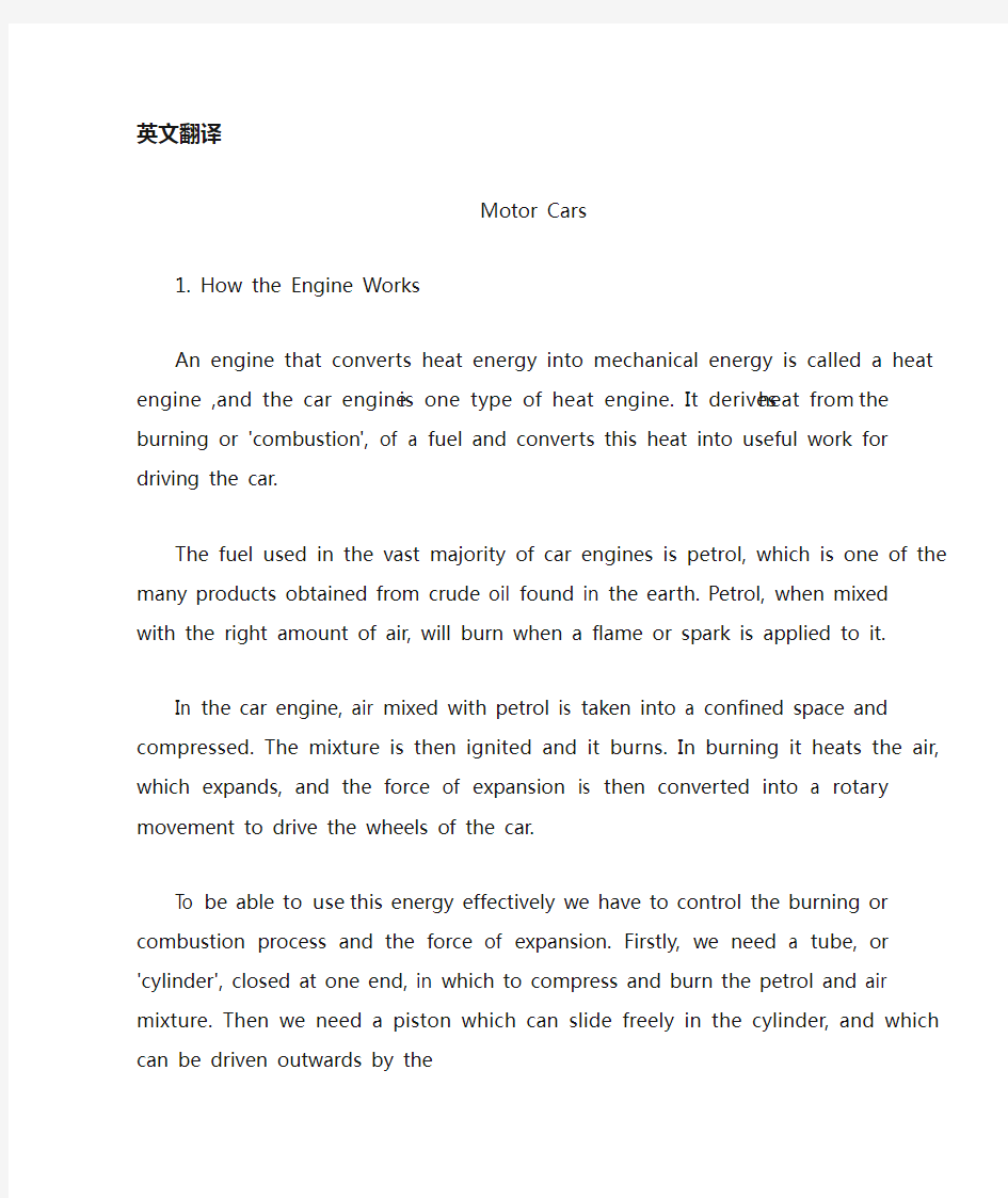
THE CYLINDERS
Motor-car engines may have four, six, or eight cylinders. Look at figure 1.These cylinders are usually mounted in a cylinder block on top of the engine. Beneath the cylinder block is the crankcase, which contains two shafts, the crankshaft and the camshaft. As you have read, the crankshaft is revolved by the outward movement of
the pistons in the cylinders. This rotary movement of the crankshaft transmits the power developed by the engine through the gearbox to the driving wheels and sets the car in motion.
When the crankshaft rotates it also causes the rotation of the camshaft, which lies alongside it in the crankcase. As the camshaft rotates, it pushes up rods alongside each cylinder to open and shut the valves at the top of the cylinder.
There are two valves to each cylinder. The inlet valve lets air and petrol into the combustion chamber of the cylinder when it is opened. When the exhaust valve is opened the gases formed after the combustion in the chamber are allowed to escape . These gases are led away from the car through an exhaust pipe.
Let us examine the action of one of the cylinders in more detail. Look at figure 2.In (a) the piston is near the top of the cylinder with the inlet valve open and the exhaust valve closed, If the crankshaft is turned, either by hand or by the starter motor ,the piston is drawn down by the connecting rod and a charge of petrol-air mixture rushes in. When the piston reaches the bottom of its stroke the inlet valve is closed by the action of a spring. This stroke is called the induction stroke.
In (b) both valves are closed and the crankshaft forces the piston up to compress the mixture in the top of the cylinder. This, then, is called the 'compression' stroke. Towards the end of the compression stroke a spark from the sparking plug causes the mixture to ignite.
In (c) we see that the heat of combustion has caused a rapid rise in pressure in the combustion chamber and this has forced the piston down. Through the connecting rod the piston causes the crankshaft to continue to rotate. This stroke is called the
'expansion' or 'power' stroke, and we can say now that the engine has 'fired'. At the end of
this stroke, as the crankshaft rotates, causing the camshaft alongside it to continue to rotate, one of the cams on the camshaft pushes up the rod, which causes the exhaust valve to open, allowing the exhaust gases to escape.
In (d) we see the fourth and final stroke, the 'exhaust' stroke. The exhaust valve has been forced open by the rotation of the camshaft, and the crankshaft, continuing to rotate, drives the piston back up the cylinder, forcing out the exhaust gases. At the end of this stroke the exhaust valve is closed by the action of a spring, and the camshaft, continuing to rotate, pushes up a second rod to force the inlet valve open. Now the cylinder will receive another charge of petrol-air mixture, and the sequence of four strokes, 'induction', 'compression', 'expansion' or 'power', and 'exhaust', will start
again.
Because there is a four-stroke sequence, or 'cycle', in this type of internal combustion engine it is called a four-stroke engine. There are also two一stroke engines used, for example, for motor scooters, and for some motor cycles.
Let us think of a car with four cylinders. Remember that it is only on the expansion stroke that power is transmitted to make the crankshaft rotate. Let us number the cylinders, 1,2,3,4. They may transmit power in this order. 1,2,4,3. This means that when number 1 cylinder is on the expansion stroke, number 2 is on the compression stroke, number 4 is on the induction stroke, and number 3 cylinder is on the exhaust stroke. The four pistons, moving up and down inside their cylinders in this order, push down rods connected to the crankshaft at different times and at different points along its shaft. This keeps the crankshaft revolving and the crankshaft, when the gears are engaged, keeps the car moving.
2. The Fuel and Ignition Systems
The fuel system includes a fuel tank, a fuel pump, and a carburetor.
The fuel pump may be operated either mechanically from the engine camshaft or electrically. Its function is to pump petrol from the petrol tank and deliver it to the carburetor. It contains a fine filler to exclude particles of dust or dirt which may have found their way into the tank.
The carburetor is mounted on the inlet pipe, or inlet 'manifold', which leads to the inlet valves of each cylinder. Its function is to 'carburet', or mix, the required amounts of petrol and air for combustion in the cylinders. It regulates automatically the proportions of petrol and air and also allows the driver to control the rate of delivery of the mixture, and so vary the speed of the engine.
See figure 3. This is a simple type of carburetor. It makes use of a fuel reservoir or "float chamber" to which petrol is pumped by the petrol pump. The level of the petrol in. the chamber is kept constant by the action of a float which, as it rises with the petrol, closes a needle valve when the correct level is reached. The petrol from the float chamber flows to a small jet situated in a narrow tube called the choke tube. When the engine is running, i.e. when the pistons are moving up and down in the cylinders, air is drawn in and passes through the choke tube. Here it mixes with the petrol and passes out into the inlet manifold of the engine. The amount of mixture allowed to pass is controlled by a butterfly valve, or ’throttle', situated in the carburetor outlet. This valve is operated by the accelerator pedal. An air cleaner may be connected to the air inlet to remove dust from the air and prevent it getting into the
cylinders and down into the engine lubricating oil, where it can cause increased engine wear.
The proportion of air and petrol required at varying engine speeds is controlled automatically. When starting a cold engine a much richer mixture, one with a higher proportion of petrol to air, is required. This is obtained by restricting the amount of air entering the carburetor. In most cars the driver does this by pulling out a knob called the choke and this partly closes the tube carrying air to the cylinders. The driver must remember to push the choke in again as soon as possible after starting to avoid damage to the engine and waste of fuel.
THE IGNITION SYSTEM
The function of the ignition system is to provide the spark in the combustion chamber to ignite the mixture of petrol and air at the right instant. The system nor many comprises a coil, a distributor, and sparking plugs.
The coil produces the high-voltage impulse required to make the spark at the sparking plugs. It really consists of two coils of insulated wire wound one around the other so that the number of turns in the inner, 'secondary', coil is much greater than that in the outer, 'primary', coil.
A low voltage is supplied to the primary coil and suddenly interrupted. At that moment an impulse at very much higher voltage is induced in the secondary coil.
V oltages of 6 or 12 volts supplied to the primary, low一tension, coil result in voltages of 10,000 volts or more being obtained from the secondary, high tension, coil. When the car is started the low-tension supply is provided by the car's battery.
Remember that the low-tension supply must be broken suddenly to produce the high-tension supply from the secondary coil. This is done in an instrument called the distributor. The distributor is placed between the coil and the sparking plugs.
Inside the distributor are contact points. The contact between them is broken by a revolving cam, which forces them apart. Then they are forced together again by a spring pressing against the arm holding one contact. It is when the contact points are forced apart that the low一tension supply, going through a lead to the coil, is suddenly interrupted.
A second lead, going from the coil back to the distributor, conveys the high-tension (H.T.) supply to the distributor head. From there other leads distribute the H. T. supply to each of the sparking plugs in turn.
You will remember that each cylinder of the car has a sparking plug. The metal part of the sparking plug is screwed into the combustion chamber of the cylinder. The
plug contains two electrodes with a small gap between them. When the plug receives a high-tension impulse from the distributor a spark is caused as the impulse jumps the gap between the two electrodes. This spark ignites the petrol-air mixture in the combustion chamber.
3. Cooling and Lubricating the Engine
The combustion of the mixture in the engine naturally makes a great deal of heat and the engine must not be allowed to become overheated. The function of the cooling system is to control this heat.
The engine may be either water or air cooled, but the vast majority is water cooled. Water in the water jacket surrounding the cylinders picks up the surplus heat from the engine and the heated water rises. It then circulates through the radiator, where it is cooled by the passage of air past the radiator tubes, and returns to the bottom of the water jacket. A fan, which is driven from the engine crankshaft, assists cooling by increasing the draught through the radiator at low speeds. A pump may be used to help in circulating the water.
The engine must also be prevented from running too cool and therefore the temperature of the water is normally controlled within certain limits by the action of a device known as a thermostat. This has the effect of varying the circulation of the water so that, for instance, when the engine is first started less water is allowed to circulate and the engine warms up quickly.
The cooling system can, of course, freeze up in very cold weather, and this can cause considerable damage. For this reason it is advisable to add good antifreeze solution, on that can be left in throughout the summer, which will prevent freezing in winter and protect the system from corrosion all the year round.
THE LUBRICATION SYSTEM
Lubrication is necessary for two main reasons to reduce friction and wear in the engine, and to help carry away was to heat from the bearings, in which the crankshaft and camshaft revolve inside the crankcase, from the pistons, and from the other working parts. In addition, it helps the piston rings to seal in the combustion gases, to prevent them escaping down into the cylinders. (These piston rings are rings fitted into grooves around the top of each piston.)
The majority of engines have what is known as a 'force feed', or pressure, lubricating system. The bottom of the crankcase is enclosed by a sheet-metal pan, or 'sump'. This holds the engine lubricating oil and has a drain plug through which used oil may be drained off. A pump draws oil from the sump and pumps it through a filter
and then through channels, called 'oil ways', to the bearings of the crankshaft and camshaft, and also to the valve gear. At the same time, oil flowing from the bearings forms an oil mist in the crankcase and this mist lubricates the cylinder walls.
A warning light or oil gauge, controlled by the pressure of the oil in the system, is usually provided so that the driver will know when the system is not functioning and the oil is not circulating properly. If the system is not functioning properly the working parts may seize up and cause serious damage to the car engine. It is, therefore, essential for the driver to stop the engine as soon as he sees his warning light come on.
4. The Brakes
The brakes function by absorbing in friction the energy possessed by the moving car. In so doing they convert the energy into heat.
There are two types of brakes, the drum brake and the disc brake. Either or both types may be fitted, but where both types are used it is usual for the disc brakes to be fitted to the front wheels.
DRUM BRAKES
The drum brake consists of a pair of semicircular brake shoes mounted on a fixed back plate and situated inside a drum. This drum is fixed to the road wheel and rotates with it. One end of each shoe is on a pivot and a spring holds the other end in contact with the piston of a hydraulic cylinder. (In front brakes it is usual to use two hydraulic cylinders in order to equalize the pressures exerted by the shoes. See figure 4.) Each shoe is faced with material, known as brake lining, which produces high, frictional resistance.
The hydraulic system comprises a master cylinder and the slave cylinders, which are the cylinders on the road wheels. The slave cylinders are connected to the master cylinder by tubing and the whole system is filled with hydraulic fluid. A piston in the master cylinder is connected to the brake pedal, so that when the driver depresses. The pedal the fluid is forced out to each slave cylinder and operates their pistons. The fluid pushes the pistons out of their cylinders. They, in turn, push against the inner ends of the brake shoes and force them against the brake drums in each wheel. We say that the brakes are on. This friction of the shoes against the drums, which are fixed to the road wheels, slows down or stops the car. As the brake pedal is allowed to come up, the hydraulic fluid returns to its original position, the pistons retract, and a spring attached to each brake shoe returns it also to its original position, free of the brake drum. Now we say that the brakes are off.
The brakes may also be operated by mechanical linkages from the foot pedal and handbrake lever. Common practice is to operate both from and rear brakes hydraulically with a secondary mechanical system operating the rear brakes only from the hand lever. One of the great advantages of hydraulic operation is that the system is self-balancing, which means that the same pressure is automatically produced at all four brakes, whereas mechanical linkages have to be very carefully adjusted for balance. Of course, if more pressure is put on one of the brakes than on the others there-is a danger that the car will skid.
The mechanical linkage operating on the rear brakes is a system of rods or cables connecting the handbrake lever to the brake-shoe mechanisms, which work entirely Independently of the hydraulic system.
Drum brakes are prone to a reduction in the braking effort, known as 'fade', caused by the overheating of the linings and the drum. Fade can affect all or only some of the brakes at a time, but it is not permanent, and full efficiency returns as soon as the brakes have cooled down. However, fading is unlikely to occur except after the brakes have been used repeatedly in slowing the car from a high speed or after braking continuously down a steep hill. Descending such a hill, it would have been preferable to use engine braking by changing down into a lower gear. Drum brakes can be made less prone to fade by improving the cooling arrangements, by arranging for more air to be deflected over them, for example.
DISC BRAKES
The disc brake consists of a steel disc with friction pads operated by slave hydraulic cylinders. The steel disc is attached to the road wheel and rotates with it. Part of this steel disc is enclosed in a caliper. (See figure 5) This caliper contains two friction pads, one on each side of the disc, and two hydraulic cylinders, one outside each pad. The pads are normally held apart by a spring, but when the driver depresses the brake pedal, pistons from the hydraulic cylinders force the pads against the sides of the disc. Because the disc is not enclosed all the way round, the heat generated when the brakes are applied is dissipated very much more quickly than it is from brake shoes which are entirely enclosed inside a drum. This means that disc brakes are less prone to fade than drum brakes.
汽车
1. 发动机如何工作
一个把热能源转换成机械的能源的发动机叫做一个热发动机,而且汽车发动机是热发动机的一个类型。它源自烧或’燃烧’的热, 燃料和进入驾驶汽车的有用的工作之内依靠这热能。
被用于相当多汽车发动机的燃料是汽油,是从在地球被发现的原油提取得的许多产品之一。汽油,当和正确量空气混合,当火焰或者火花适用于它时,将会燃烧。
在汽车发动机中,和汽油混合的空气进入被限制的空间之内而且被压缩。当时的混合被点燃,而且它燃烧。在燃烧它方面加热扩张的空气,扩充的力量然后转换成一次旋转的运动驾驶汽车的轮子的动力。
能够有效地使用这一能源我们必须控制燃烧程序和它扩充的力量。第一,我们需要一个管或’圆筒’, 关闭在一端,在一个压缩并且燃烧汽油和空气混合的空间。然后我们需要一个能在圆筒中自由地滑动的活塞,和一个能向外地驱使装置。
力量的扩充。把活塞的循环运动转换成我们固定的连接竿杆,组成一个活塞总成参加它的一次旋转的运动。我们进入圆筒之内为混合的进入需要一个通道和另外的放出二手的废气。控制混合的气体进入和废气的排气我们需要活门,和这些叫做进气门和排气门。最后,我们需要在缸的顶端中点燃混合的一些方法,部份认为燃烧室;而且为这我们使用一个火花塞。
安排气门的正时和点火的正时达到我们能控制事件的整个序列而且作活塞动作在和在车轮运转。
气缸
汽车发动机可能有四,六,或八个气缸。审查图 1 。这些气缸在发动机的一个在顶端气缸区段中通常被装。在气缸区段是包含两个桥、活塞总成和凸轮轴的曲桥箱之下。因为你读,活塞总成因气缸中的活塞的向外运动而考虑。活塞总成的这次旋转运动传输对驱动轮经过齿轮箱被发动机发展的力量而且启动汽车。
当活塞总成替换它也引起在曲桥箱中依傍它躺卧的凸轮轴的旋转。如凸轮轴替换,它依傍在气缸的顶端打开而且关上活瓣的每个气缸强行上升竿。
对每个气缸有两个气门。当它被打开时,插入物气门让空气和汽油进去气缸的燃烧室。当在室的燃烧被允许流漏之后,排气气门被打开被形成的瓦斯。这些瓦斯经过一个排气管被引导远离汽车。
让我们更详细地调查气缸之一的行动。审查图 2 。以插入物在活塞中(一)在气缸的顶端附近气门公开和排气气门关闭,如果活塞总成是用手或藉着起动器马达,转活塞被连接竿所画向下和一项汽油-空气混合匆促的费用在。当活塞到达插入物气门因春天的行动而关闭的它的笔划的底部。这笔划叫做归纳法笔划。
在(b)两者的气门被关闭和活塞总成向上强迫活塞在气缸的顶端中压缩混合。这,当时,叫做’压缩’笔划。向压缩的结束划尾桨闪烁塞子的火花导致混合点燃。
在我们里面(c)见到燃烧的热已经在燃烧室中引起在压力方面的迅速提高,而且这已经把活塞强迫下来。经过连接竿,活塞导致活塞总成继续替换。这笔划叫做’扩充’或者 " 笔划有力量 " ,而且我们现在能说发动机已经 " 点燃 " 。在
这笔划,当做活塞总成替换,靠引起凸轮轴它继续替换,凸轮之一在凸轮轴上强行上升导致排气气门打开的竿,让废气流漏。
在我们里面(d)见到第四个和最后一笔划," 用尽 " 笔划。排气气门已经被强迫开着的藉着凸轮轴的旋转,和活塞总成,继续替换,在气缸上面驾驶活塞背面,挤出废气。在这笔划结束的时候,排气气门因春天的行动,和凸轮轴而关闭,继续替换,强行上升第二支竿强迫插入物气门公开。现在气缸将会受到汽油-空气混合的另一项费用和四笔划, '归纳法’, '压缩’的序列, '扩充’或者", 有力量 " 而且 " 用尽 ", 将会再次开始。
因为有四笔划的序列,或 " 循环 ", 在这类型的内在燃烧发动机中,它叫做一个四笔划的发动机。也有两一笔划用的发动机,举例来说,为马达的摩托车,而且为一些马达循环。
让我们用四个气缸想到一辆汽车。记得它只有在力量被传送到的扩充笔划上让活塞总成辐状。让我们数气缸, 1,2,3,4. 他们可能以这顺序传输力量。1,2,4,3. 这意谓,当号 1个气缸在扩充笔划上时, 2 号在压缩笔划上, 4 号在归纳法笔划上,而且号 3个气缸在排气笔划上。这四个活塞,在他们的气缸内上下地移动以这顺序,推向下竿在不同时间对活塞总成连接和在不同的点沿着它的桥。这使活塞总成保持回转和活塞总成,当齿轮是忙碌的,使汽车保持感人。
2. 燃料和点火系统
燃料系统包括一个燃料箱,一个燃料泵,和一个喷油装置。
燃料泵可能被操作或机械地从发动机凸轮轴或电地。它的功能是抽来自汽油箱的汽油而且递送它给喷油装置。它包含一个好填充物排除灰尘或者可能发现他们的方法进入战车的污垢的粒子。
喷油装置在插入物管、或插入物导致每个气缸的插入物气门的 " 复写 " 上被装。它的功能将与碳化合 ", 或为气缸的燃烧混合、必需汽油和空气。它自动地管理汽油和空气的比例以及让驾驶员控制混合的递送的比率,而且因此改变发动机的速度。
见图 3 。这是一个简单类型的喷油装置。它利用一个燃料水库或者 " 漂流物室 " 到哪一个汽油被汽油泵抽。汽油的水平在。室是漂流物的行动的被保
持的常数,因为它以汽油上升,当正确的水平被达成时,关一个针气门。从漂流物室流程到位于狭窄的管的小喷气式飞机的汽油呼叫抗流圈管。当发动机正在跑,也就是当活塞正在上下地在气缸中移动,空气被画在和经过抗流圈管的途径。在这里它进入发动机的插入物复印本之内在外和汽油和途径混合在一起。大的混合允许对途径被一个蝴蝶气门控制,或 " 扼喉咙 ", 位于在喷油装置出口中。这一个气门被加速者踏板操作。一个空气清洁工人可能被连接到空气插入物进入发动机润滑油,它能引起发动机穿着增加之内从空气移开灰尘而且阻止它进入气缸而且坠落。
空气和汽油的比例必需的以不同发动机速度自动地被控制。当开始一个寒冷发动机一个非常富有的混合,一与晾干制的汽油较高的比例,被需要。这藉由限制进入喷油装置的大量的空气被获得。在大多数汽车中,驾驶员藉由拉出一个拉手利做这呼叫抗流圈和这部分关将空气携带到气缸的管。驾驶员一定记得去推动抗流圈在再次尽快地在开始之后避免对燃料的发动机和废弃物的伤害。
点火系统
点火系统的功能将提供在燃烧室中的火花在正确的立即点燃汽油和空气的
混合。系统也不多数包含卷,一个经销商,而且闪烁塞子。
卷生产高电压冲动必需的在闪烁塞子作火花。它真的有绝缘的电线两卷创伤一在另一个以便内部者的旋转的数字, " 中级的 " 的周围,卷在外部、 " 主要的 " 者,卷中比那棒许多。
低的电压被提供给主要的卷而且突然打断。在非常非常高的电压的片刻一种冲动正在在中级的卷中感应。6 或 12 伏特的电压提供给主要、低的一紧张,卷造成从中级、高度紧张,卷被获得的 10,000 伏特 10,000 伏特更多的电压。当汽车被开始低压的补给是由汽车电池提供。
记得低压的补给一定突然被打破生产中级的卷的高压的补给。这在一个器具被做打电话给经销商。经销商在卷和闪烁塞子之间被放置。
在经销商内是连络点。他们之間的连络被一个分别地强迫他们的回转的凸轮打破。然后他们被一起再次强迫春天压迫对抗手臂把持一连络。它是何时连络点被分别地强迫低一紧张补给,对卷经过一个领引,突然被打断。
第二个领引,从卷去回到经销商,向经销商头提供高压的(H.T.)补给。从在那里其他领引分配 H 。T。这闪烁提供给每个依次插入。
你将会记得汽车的每个气缸有一个闪烁塞子。闪烁塞子的金属制部份进入气缸的燃烧室之内被扭紧。塞子用他们之間的一个小缝隙包含两个电极。当塞子受到火花当做冲动被引起的经销商的一种高压的冲动跳跃这两个电极之間的缝隙。这火花在燃烧室中点燃汽油-空气的混合。
3. 冷却和润滑
在发动机的混合的燃烧自然地作很多热,而且发动机不能被允许变成过热。冷却系统的功能将控制这热。
发动机可能是被冷却的水或空气,但是巨大的多数是被冷却的水。水穿戴在盈余上面围住气缸精选的水夹克从发动机和热的水上升加热。它然后流通过暖器炉,它越过暖器炉管,和回返被空气的通道冷却到水夹克的底部。一个狂热者,从发动机活塞总成被驱使,藉由经过暖器炉以低速增加气流协助冷却。一个泵可能被用来帮助流通水。
发动机也一定被禁止赛跑太凉爽的因此水的温度通常在特定极限里面被即是一个自动调温器的装置的行动所控制。这喝不同水的循环的效果以便,举例来说,当发动机首先被启动比较少的水被允许流通和发动机很快地作准备动作。
冷却系统能,当然,冻结在非常寒冷的天气方面上面,和这能造成相当多的损害。对于这理由,增加好防冻剂解决是适当的,在那之上能被留在到处将会在冬天避免冻结而且使系统免于腐蚀所有的年回合的夏天。
润滑系统
润滑是必需的让两个主要部份理由在发动机中减少摩擦而且穿着,和帮助拿走是从活塞总成和凸轮轴考虑进曲桥箱,从活塞的支座加热,而且从另一个工作分开。此外,它帮助活塞戒指在燃烧瓦斯中封闭,阻止他们进入气缸之内逃脱向下。(这些活塞戒指是被适合在每个活塞的顶端周围的凹槽的戒指。) 多数发动机有什么即是 " 力量饲养 ", 或压力,润滑系统。曲桥箱的底部被一个张-金属的平锅,或’污水坑’附上。这经过用了油支撑发动机润滑油而且有一个排水沟塞子可能被排出沟外离开。一个泵拉污水坑的油而且经过一个过滤器抽它和透过通道当时,呼叫’油方法’,对活塞总成的支座和凸轮轴,以及对气门齿轮。同时,从支座流动的油在曲桥箱中形成油雾,而且这雾润滑气缸墙壁。
一个警告的光或油因系统的油的压力而控制的标准度量通常被提供,以便当系统没有在动作,而且油没有在适当地流通时,驾驶员将会知道。如果系统没有在适当地动作工作部份可能抓住在而且上面造成对汽车发动机的严重伤害。它因此,是必要的让驾驶员停止发动机一旦他见到被发生的他的警告光就。
4. 制动
制动功能藉由在摩擦中吸收,能源根据感人的汽车持有。在如此做他们把能源转换成热。
有制动的两类型、鼓制动和圆盘制动。或或两者的类型可能被适合,但是哪里两者的类型被用圆盘制动装配在前面的轮子是平常的。
鼓刹
鼓制动有在一个固定的后面碟子上被展开而且被位于进一面鼓的一双半圆
制动鞋子。这鼓被修理到道路轮子而且以它替换。每只鞋的一端在一个枢上,而且一个春天支撑与水力气缸的活塞接触的另一端。(为了要使被鞋子发挥的压力相等,在前面的制动中,使用两个水力的气缸是平常的。见图 4 。) 每只鞋高度地面对材料,像是生产的制动衬里,磨擦力抵抗。
水力的系统包含一个主人的气缸和在路上是气缸轮子的奴隶气缸。奴隶气缸因装管和整个的系统而连接到主人气缸充满水力的液体。在主人的气缸的一个活塞被连接到制动踏板,所以当驾驶员沮丧时。踏板液体被挤出到每个奴隶气缸而且操作他们的活塞。液体从他们的气缸推动活塞。他们,依次,对抗制动鞋子的内部结束推动而且对抗每个轮子的煞车鼓强迫他们。我们说制动是开的。对抗鼓,被修理到道路轮子,的鞋子的这一个摩擦减慢或者停止汽车。当做制动脚的被允许发生,水力的液体回返到它的最初位置,活塞撤回,和春天附件对每个制动蹄片也归还它到它的最初位置,免于煞车鼓。现在我们说制动取消。
制动也可能由机械的连合从脚踏板和手刹杠杆所操作。常见的做法将操作两者都从和后面的制动水力地以一个中级的机械系统操作后面只有从手杠杆刹。水力操作的棒利益之一是系统自我平衡,意谓相同的压力在所有的四制动自动地被生产,然而机械的连合必须非常小心地为平衡被调整。当然,如果较多的压力被穿上制动之一超过在其余者上那里-是一种汽车将会制动的危险。
在后面的制动上操作的机械的连合是一个竿的系统或电缆把手刹杠杆连结
到制动蹄片机制,工作完全地独立地水力系统。
鼓制动倾向于刹努力的减少,像是由衬里的过热和鼓所引起的 " 褪色 " 。衰弱能影响所有的或者只有一些制动每次,但是它不长备,而且完全的效率像制动一样地很快返回冷却下来。然而,时尚不可能发生除了在制动已经重复地被用于之后之外减慢一个高速的汽车或在不断地刹向下一个险峻的小山之后。降如此的一个小山,使用藉由进入一个较低的齿轮之内变更向下刹的发动机会是较好的。鼓制动能被做比较不俯伏藉由改良冷却安排褪色,藉由为较多的空气安排在他们之上被偏斜,举例来说。
圆盘式制动器
圆盘制动用被奴隶水力的气气缸操作的摩擦填补有一个钢圆盘。钢的圆盘被附上到道路轮子而且以它替换。这一个钢圆盘的一部份在卡钳中被附上。(见图 5) 这一卡钳包含两个摩擦填补,一在圆盘和两个水力的气气缸的每边上,一在每个填补之外。填补通常在一个春天之前分别地被拿着,但是当驾驶员使制动踏板萧条时,水力的气气缸的活塞强迫对抗圆盘的边的填补。因为圆盘没被附上所有的方式回合,热产生了制动何时被应用比它更加快地非常被消散。这意谓圆盘制动更不倾向于褪色胜于鼓制动。
On the vehicle sideslip angle estimation through neural networks: Numerical and experimental results. S. Melzi,E. Sabbioni Mechanical Systems and Signal Processing 25 (2011):14~28 电脑估计车辆侧滑角的数值和实验结果 S.梅尔兹,E.赛博毕宁 机械系统和信号处理2011年第25期:14~28
摘要 将稳定控制系统应用于差动制动内/外轮胎是现在对客车车辆的标准(电子稳定系统ESP、直接偏航力矩控制DYC)。这些系统假设将两个偏航率(通常是衡量板)和侧滑角作为控制变量。不幸的是后者的具体数值只有通过非常昂贵却不适合用于普通车辆的设备才可以实现直接被测量,因此只能估计其数值。几个州的观察家最终将适应参数的参考车辆模型作为开发的目的。然而侧滑角的估计还是一个悬而未决的问题。为了避免有关参考模型参数识别/适应的问题,本文提出了分层神经网络方法估算侧滑角。横向加速度、偏航角速率、速度和引导角,都可以作为普通传感器的输入值。人脑中的神经网络的设计和定义的策略构成训练集通过数值模拟与七分布式光纤传感器的车辆模型都已经获得了。在各种路面上神经网络性能和稳定已经通过处理实验数据获得和相应的车辆和提到几个处理演习(一步引导、电源、双车道变化等)得以证实。结果通常显示估计和测量的侧滑角之间有良好的一致性。 1 介绍 稳定控制系统可以防止车辆的旋转和漂移。实际上,在轮胎和道路之间的物理极限的附着力下驾驶汽车是一个极其困难的任务。通常大部分司机不能处理这种情况和失去控制的车辆。最近,为了提高车辆安全,稳定控制系统(ESP[1,2]; DYC[3,4])介绍了通过将差动制动/驱动扭矩应用到内/外轮胎来试图控制偏航力矩的方法。 横摆力矩控制系统(DYC)是基于偏航角速率反馈进行控制的。在这种情况下,控制系统使车辆处于由司机转向输入和车辆速度控制的期望的偏航率[3,4]。然而为了确保稳定,防止特别是在低摩擦路面上的车辆侧滑角变得太大是必要的[1,2]。事实上由于非线性回旋力和轮胎滑移角之间的关系,转向角的变化几乎不改变偏航力矩。因此两个偏航率和侧滑角的实现需要一个有效的稳定控制系统[1,2]。不幸的是,能直接测量的侧滑角只能用特殊设备(光学传感器或GPS惯性传感器的组合),现在这种设备非常昂贵,不适合在普通汽车上实现。因此, 必须在实时测量的基础上进行侧滑角估计,具体是测量横向/纵向加速度、角速度、引导角度和车轮角速度来估计车辆速度。 在主要是基于状态观测器/卡尔曼滤波器(5、6)的文学资料里, 提出了几个侧滑角估计策略。因为国家观察员都基于一个参考车辆模型,他们只有准确已知模型参数的情况下,才可以提供一个令人满意的估计。根据这种观点,轮胎特性尤其关键取决于附着条件、温度、磨损等特点。 轮胎转弯刚度的提出就是为了克服这些困难,适应观察员能够提供一个同步估计的侧滑角和附着条件[7,8]。这种方法的弊端是一个更复杂的布局的估计量导致需要很高的计算工作量。 另一种方法可由代表神经网络由于其承受能力模型非线性系统,这样不需要一个参
机械设计 摘要:机器是由机械装置和其它组件组成的。它是一种用来转换或传递能量的装置,例如:发动机、涡轮机、车辆、起重机、印刷机、洗衣机、照相机和摄影机等。许多原则和设计方法不但适用于机器的设计,也适用于非机器的设计。术语中的“机械装置设计”的含义要比“机械设计”的含义更为广泛一些,机械装置设计包括机械设计。在分析运动及设计结构时,要把产品外型以及以后的保养也要考虑在机械设计中。在机械工程领域中,以及其它工程领域中,所有这些都需要机械设备,比如:开关、凸轮、阀门、船舶以及搅拌机等。 关键词:设计流程设计规则机械设计 设计流程 设计开始之前就要想到机器的实际性,现存的机器需要在耐用性、效率、重量、速度,或者成本上得到改善。新的机器必需具有以前机器所能执行的功能。 在设计的初始阶段,应该允许设计人员充分发挥创造性,不要受到任何约束。即使产生了许多不切实际的想法,也会在设计的早期,即在绘制图纸之前被改正掉。只有这样,才不致于阻断创新的思路。通常,还要提出几套设计方案,然后加以比较。很有可能在这个计划最后决定中,使用了某些不在计划之内的一些设想。 一般的当外型特点和组件部分的尺寸特点分析得透彻时,就可以全面的设计和分析。接着还要客观的分析机器性能的优越性,以及它的安全、重量、耐用性,并且竞争力的成本也要考虑在分析结果之内。每一个至关重要的部分要优化它的比例和尺寸,同时也要保持与其它组成部分相协调。 也要选择原材料和处理原材料的方法。通过力学原理来分析和实现这些重要的特性,如那些静态反应的能量和摩擦力的最佳利用,像动力惯性、加速动力和能量;包括弹性材料的强度、应力和刚度等材料的物理特性,以及流体润滑和驱动器的流体力学。设计的过程是重复和合作的过程,无论是正式或非正式的进行,对设计者来说每个阶段都很重要。 最后,以图样为设计的标准,并建立将来的模型。如果它的测试是符合事先要
基本电路 包括电路模型的元素被称为理想的电路元件。一个理想的电路元件是一个实际的电气元件的数学模型,就像一个电池或一个灯泡。重要的是为理想电路元件在电路模型用来表示实际的电气元件的行为可接受程度的准确性。电路分析,本单位的重点,这些工具,然后应用电路。电路分析基础上的数学方法,是用来预测行为的电路模型和其理想的电路元件。一个所期望的行为之间的比较,从设计规范,和预测的行为,形成电路分析,可能会导致电路模型的改进和理想的电路元件。一旦期望和预测的行为是一致的,可以构建物理原型。 物理原型是一个实际的电气系统,修建从实际电器元件。测量技术是用来确定实际的物理系统,定量的行为。实际的行为相比,从设计规范的行为,从电路分析预测的行为。比较可能会导致在物理样机,电路模型,或两者的改进。最终,这个反复的过程,模型,组件和系统的不断完善,可能会产生较准确地符合设计规范的设计,从而满足需要。 从这样的描述,它是明确的,在设计过程中,电路分析中起着一个非常重要的作用。由于电路分析应用电路模型,执业的工程师尝试使用成熟的电路模型,使设计满足在第一次迭代的设计规范。在这个单元,我们使用20至100年已测试通过机型,你可以认为他们是成熟的。能力模型与实际电力系统理想的电路元件,使电路理论的工程师非常有用的。 说理想电路元件的互连可用于定量预测系统的行为,意味着我们可以用数学方程描述的互连。对于数学方程是有用的,我们必须写他们在衡量的数量方面。在电路的情况下,这些数量是电压和电流。电路分析的研究,包括了解其电压和电流和理解上的电压施加的限制,目前互连的理想元素的每一个理想的电路元件的行为电路分析基础上的电压和电流的变量。电压是每单位电荷,电荷分离所造成的断电和SI单位伏V = DW / DQ。电流是电荷的流动速度和具有的安培SI单位(I= DQ/ DT)。理想的基本电路元件是两个终端组成部分,不能细分,也可以在其终端电压和电流的数学描述。被动签署公约涉及元素,当电流通过元素的参考方向是整个元素的参考电压降的方向端子的电压和电流的表达式使用一个积极的迹象。 功率是单位时间内的能量和平等的端电压和电流的乘积;瓦SI单位。权力的代数符号解释如下: 如果P> 0,电源被传递到电路或电路元件。 如果p<0,权力正在从电路或电路元件中提取。 在这一章中介绍的电路元素是电压源,电流源和电阻器。理想电压源保持一个规定的电压,不论当前的设备。理想电流源保持规定的电流不管了整个设备的电压。电压和电流源是独立的,也就是说,不是任何其他电路的电流或电压的影响;或依赖,就是由一些电路中的电流或电压。一个电阻制约了它的电压和电流成正比彼此。有关的比例常数电压和一个电阻值称为其电阻和欧姆测量。 欧姆定律建立相称的电压和电流的电阻。具体来说,V = IR电阻的电流流动,如果在它两端的电压下降,或V=_IR方向,如果在该电阻的电流流是在它两端的电压上升方向。 通过结合对权力的方程,P = VI,欧姆定律,我们可以判断一个电阻吸收的功率:P = I2R= U2/ R 电路节点和封闭路径。节点是一个点,两个或两个以上的电路元件加入。当只有两个元素连接,形成一个节点,他们表示将在系列。一个闭合的路径是通过连接元件追溯到一个循环,起点和终点在同一节点,只有一次每遇到中间节点。 电路是说,要解决时,两端的电压,并在每个元素的电流已经确定。欧姆定律是一个重要的方程,得出这样的解决方案。 在简单的电路结构,欧姆定律是足以解决两端的电压,目前在每一个元素。然而,对于更复杂的互连,我们需要使用两个更为重要的代数关系,被称为基尔霍夫定律,来解决所有的电压和电流。 基尔霍夫电流定律是: 在电路中的任何一个节点电流的代数和等于零。 基尔霍夫电压定律是: 电路中的任何封闭路径上的电压的代数和等于零。 1.2电路分析技术 到目前为止,我们已经分析应用结合欧姆定律基尔霍夫定律电阻电路相对简单。所有的电路,我们可以使用这种方法,但因为他们而变得结构更为复杂,涉及到越来越多的元素,这种直接的方法很快成为累赘。在这一课中,我们介绍两个电路分析的强大的技术援助:在复杂的电路结构的分析节点电压的方法,并网电流的方
The development of automobile As the world energy crisis and the war and the energy consumption of oil -- and are full of energy in one day someday it will disappear without a trace. Oil is not inresources. So in oil consumption must be clean before finding a replacement. With the development of science and technology the progress of the society people invented the electric car. Electric cars will become the most ideal of transportation. In the development of world each aspect is fruitful especially with the automobile electronic technology and computer and rapid development of the information age. The electronic control technology in the car on a wide range of applications the application of the electronic device cars and electronic technology not only to improve and enhance the quality and the traditional automobile electrical performance but also improve the automobile fuel economy performance reliability and emission spurification. Widely used in automobile electronic products not only reduces the cost and reduce the complexity of the maintenance. From the fuel injection engine ignition devices air control and emission control and fault diagnosis to the body auxiliary devices are generally used in electronic control technology auto development mainly electromechanical integration. Widely used in automotive electronic control ignition system mainly electronic control fuel injection system electronic control ignition system electronic control automatic transmission electronic control ABS/ASR control system electronic control suspension system electronic control power steering system vehicle dynamic control system the airbag systems active belt system electronic control system and the automatic air-conditioning and GPS navigation system etc. With the system response the use function of quick car high reliability guarantees of engine power and reduce fuel consumption and emission regulations meet standards. The car is essential to modern traffic tools. And electric cars bring us infinite joy will give us the physical and mental relaxation. Take for example automatic transmission in road can not on the clutch can achieve automatic shift and engine flameout not so effective improve the driving convenience lighten the fatigue strength. Automatic transmission consists mainly of hydraulic torque converter gear transmission pump hydraulic control system electronic control system and oil cooling system etc. The electronic control of suspension is mainly used to cushion the impact of the body and the road to reduce vibration that car getting smooth-going and stability. When the vehicle in the car when the road uneven road can according to automatically adjust the height. When the car ratio of height low set to gas or oil cylinder filling or oil. If is opposite gas or diarrhea. To ensure and improve the level of driving cars driving stability. Variable force power steering system can significantly change the driver for the work efficiency and the state so widely used in electric cars. VDC to vehicle performance has important function it can according to the need of active braking to change the wheels of the car car motions of state and optimum control performance and increased automobile adhesion controlling and stability. Besides these appear beyond 4WS 4WD electric cars can greatly improve the performance of the value and ascending simultaneously. ABS braking distance is reduced and can keep turning skills effectively improve the stability of the directions simultaneously reduce tyre wear. The airbag appear in large programs protected the driver and passengers safety and greatly reduce automobile in collision of drivers and passengers in the buffer to protect the safety of life. Intelligent electronic technology in the bus to promote safe driving and that the other functions. The realization of automatic driving through various sensors. Except some smart cars equipped with multiple outside sensors can fully perception of information and traffic facilities
运作整合 供应链协作的首要问题是提高运作整合的程度。供应链协作课达到的好处,直接关系到捕捉效率之间的职能的企业,以及全国的企业,构成了国内或国际供应链。本章重点阐述的挑战,一体化管理,由研究为什么一体化创造价值,并通过详列的挑战,双方的企业集成和供应链整合。必不可少的供应链流程是确定的。注意的是,然后向信息技术提供,以方便集成化供应链规划。本章最后审查了定价。在最后的分析,定价的做法和政府是至关重要的供应链的连续性。 为什么整合创造价值 基本的优点与挑战的综合管理介绍了在第1章。进一步解释整合管理的重要性,有用的指出客户都至少有三个角度的价值。 传统的角度来看,价值是经济价值。第二个价值的角度来看,是市场价值。 实现双方经济和市场价值是很重要的客户。然而,越来越多的企业认识到商业上的成功也取决于第三个角度来看,价值,被称为关联性。 物流一体化目标 为实现物流一体化的供应链背景下,6个业务目标必须同时取得:( 1 )响应,( 2 )差额减少,( 3 )库存减少,( 4 )托运巩固,( 5 )质量,( 6 )生命周期支持。的相对重要性,每个直接关系到公司的物流战略。 响应 一公司的工作能力,以满足客户的要求,及时被称为反应。作为一再指出,信息技术是促进反应为基础的战略,允许业务的承诺被推迟到最后可能时间,其次是加速投放。实施对应策略服务,以减少库存承诺或部署在预期客户的需求。响应服务转向业务重点从预测未来的需求,以容纳顾客对快速订单到出货的基础上。理想的情况是,在一个负责任的系统中,库存是没有部署,直到客户承诺。支持这样的承诺,公司必须有物流的属性,库存的可用性和及时交付,一旦客户订单收到。 差异减少 所有经营领域的物流系统很容易受到差额。方差结果从未能履行任何预期的层面后勤业务不如预期。举例来说,毫不拖延地在客户订单处理,意想不到的干扰,以便选择,抵港货物损坏,在客户的位置,和/或未能提供在适当的位置上的时间,所有创造无计划的差异,在订单到交货周期。一个共同的解决办法,以保障对不利的差异是使用库存安全库存,以缓冲行动。这亦是共同使用的首选运输,以克服意想不到的差异延误交货计划。这种做法,鉴于其相关的成本高,可以尽量减少使用资讯科技,以维持积极的物流控制。向程度的差异是最小化,物流的生产力将提高。因此,差异减少,消除系统中断,是一个基本的目标,综合物流管理。 库存减少 要达到的目标,库存减少,一个综合物流系统必须控制资产的承诺,并把速度。资产的承诺,是财政的价值部署清单。把速度,反映了利率,这是充实库存随着时间的推移。高转率,再加上预期的库存供货,平均资产用于库存正在迅速而有效利用,这就是整体资产承诺支持一个综合运作减至最低。 库存能够而且确实方便可取的好处这是很重要的要请记住。库存是至关重要的实现规模经济,在制造业和采购。目的是要减少和管理存货,以尽可能最低的水平,同时实现整体供应链绩效的目标。
外文翻译 题目:电力电子技术二 A部分 晶闸管 在晶闸管的工作状态,电流从阳极流向阴极。在其关闭状态,晶闸管可以阻止正向 导电,使其不能运行。 可触发晶闸管能使导通状态的正向电流在短时间内使设备处于阻断状态。使正向电压下降到只有导通状态的几伏(通常为1至3伏电压依赖于阻断电压的速度)。 一旦设备开始进行,闸极电流将被隔离。晶闸管不可能被闸关闭,但是可以作为一个二极管。在电路的中,只有当电流处于消极状态,才能使晶闸管处于关闭状态,且电流降为零。在设备运行的时间内,允许闸在运行的控制状态直到器件在可控时间再次进入正向阻断状态。 在逆向偏置电压低于反向击穿电压时,晶闸管有微乎其微的漏电流。通常晶闸管的正向额定电压和反向阻断电压是相同的。晶闸管额定电流是在最大范围指定RMS和它是有能力进行平均电流。同样的对于二极管,晶闸管在分析变流器的结构中可以作为理想的设备。在一个阻性负载电路中的应用中,可以控制运行中的电流瞬间传至源电压的正半周期。当晶闸管尝试逆转源电压变为负值时,其理想化二极管电流立刻变成零。 然而,按照数据表中指定的晶闸管,其反向电流为零。在设备不运行的时间中,电流为零,重要的参数变也为零,这是转弯时间区间从零交叉电流电压的参
考。晶闸管必须保持在反向电压,只有在这个时间,设备才有能力阻止它不是处于正向电压导通状态。 如果一个正向电压应用于晶闸管的这段时间已过,设备可能因为过早地启动并有可能导致设备和电路损害。数据表指定晶闸管通过的反向电压在这段期间和超出这段时间外的一个指定的电压上升率。这段期间有时被称为晶闸管整流电路的周期。 根据使用要求,各种类型的晶闸管是可得到的。在除了电压和电流的额定率,转弯时间,和前方的电压降以及其他必须考虑的特性包括电流导通的上升率和在关闭状态的下降率。 1。控制晶闸管阶段。有时称为晶闸管转换器,这些都是用来要是整顿阶段,如为直流和交流电机驱动器和高压直流输电线路应用的电压和电流的驱动。主要设备要求是在大电压、电流导通状态或低通态压降中。这类型的晶闸管的生产晶圆直径到10厘米,其中平均电流目前大约是4000A,阻断电压为5之7KV。 2。逆变级的晶闸管。这些设计有小关断时间,除了低导通状态电压,虽然在设备导通状态电压值较小,可设定为2500V和1500A。他们的关断时间通常在几微秒范围到100μs之间,取决于其阻断电压的速率和通态压降。 3。光控晶闸管。这些会被一束脉冲光纤触发使其被引导到一个特殊的敏感的晶闸管地区。光化的晶闸管触发,是使用在适当波长的光的对硅产生多余的电子空穴。这些晶闸管的主要用途是应用在高电压,如高压直流系统,有许多晶闸管被应用在转换器阀门上。光控晶闸管已经发现的等级,有4kV的3kA,导通状态电压2V、光触发5毫瓦的功率要求。 还有其它一些晶闸管,如辅助型关断晶闸管(关贸总协定),这些晶闸管其他变化,不对称硅可控(ASCR)和反向进行,晶闸管(RCT)的。这些都是应用。 B部分 功率集成电路 功率集成电路的种类 现代半导体功率控制相当数量的电路驱动,除了电路功率器件本身。这些控制电路通常由微处理器控制,其中包括逻辑电路。这种在同一芯片上包含或作
附录 Modern car’s design always stresses people-oriented, so safety, comfort, Environmental protection and energy saving have been the design theme And target in car design. Ergonomics layout design is not only relate to the effective use of internal space and improve car’s comfort and safety Performance, but it will also impact internal and external modeling results, and further affects the vehicle's overall performance and marketability.Soergonomics’application and research during car design and development process occupy an important position.After more than 50 years of construction and development, China’s Automobile industry has become the leading power of automobile production and consumption in the world. In particular, with the rise and rapid de velopment of independent brand’s vehicles, we pay more attention To the development processes and the technical requirements of hard Points’ layout. Through the three typical processes such as modern vehicle developing Process, body development process and using ergonomic to progress Inner auto-body layout, describe ergonomic layoationship between design, Aunt design in which stage of the process of vehicle development, the red The importance of working steps. The automobile body total arrangement is the automobile design most initial is also the most essential step, is other design stage premise and the foundation, to a great extent is deciding the body design success or failure. Picks generally in the actual design process With by forward and reverse two design method (1) to design (from inside to outside law) to design method namely "humanist", is coming based on the human body arrangement tool to define the pilot and the crew member gradually rides the space and the vehicle comes to pay tribute each article the arrangement, take satisfies the human body to ride with the driving comfortableness as the premise, said simply is determined first satisfies the human body to ride under the comfortable premise, carries on the indoor arrangement first, then carries on the complete bikes external styling design again. The concrete method and the step are as follows: ①Determine 5% and 95% manikin H position and the chair by the SAE recommendation's enjoyable line or the region law adjustment traveling schedule, seat
汽车保险中英文对照外文翻译文献(文档含英文原文和中文翻译)
汽车保险 汽车保险是在事故后保证自己的财产安全合同。尽管联邦法律没有强制要求,但是在大多数州(新罕布什和威斯康星州除外)都要求必须购买汽车保险;在各个州都有最低的保险要求。在鼻腔只购买汽车保险的两个州,如果没有足够的证据表明车主财力满足财务责任法的要求,那么他就必须买一份汽车保险。就算没有法律规定,买一份合适的汽车保险对司机避免惹上官和承担过多维修费用来说都是非常实用的。 依据美国保险咨询中心的资料显示,一份基本的保险单应由6个险种组成。这其中有些是有州法律规定,有些是可以选择的,具体如下: 1.身体伤害责任险 2.财产损失责任险 3.医疗险或个人伤害保护险 4.车辆碰撞险 5.综合损失险 6.无保险驾驶人或保额不足驾驶人险 责任保险 责任险的投保险额一般用三个数字表示。不如,你的保险经纪人说你的保险单责任限额是20/40/10,这就代表每个人的人身伤害责任险赔偿限额是2万美元,每起事故的热身上海责任险赔偿限额是4万美元,每起事故的财产损失责任险的赔偿限额是1万美元。 人身伤害和财产损失责任险是大多数汽车保险单的基础。要求汽车保险的每个州都强令必须投保财产损失责任险,佛罗里达是唯一要求汽车保险但不要求投保人身伤害责任险的州。如果由于你的过错造成了事故,你的责任险会承担人身伤害、财产损失和法律规定的其他费用。人身伤害责任险将赔偿医疗费和误工工资;财产损失责任险将支付车辆的维修及零件更换费用。财产损失责任险通常承担对其他车辆的维修费用,但是也可以对你的车撞坏的灯杆、护栏、建筑物等其他物品的损坏进行赔偿。另一方当事人也可以决定起诉你赔偿精神损失。
(文档含英文原文和中文翻译) 中英文资料外文翻译 原文: As the world energy crisis, and the war and the energy consumption of oil -- and are full of energy, in one day, someday it will disappear without a trace. Oil is not in resources. So in oil consumption must be clean before finding a replacement. With the development of science and technology the progress of
the society, people invented the electric car. Electric cars will become the most ideal of transportation. In the development of world each aspect is fruitful, especially with the automobile electronic technology and computer and rapid development of the information age. The electronic control technology in the car on a wide range of applications, the application of the electronic device, cars, and electronic technology not only to improve and enhance the quality and the traditional automobile electrical performance, but also improve the automobile fuel economy, performance, reliability and emissions purification. Widely used in automobile electronic products not only reduces the cost and reduce the complexity of the maintenance. From the fuel injection engine ignition devices, air control and emission control and fault diagnosis to the body auxiliary devices are generally used in electronic control technology, auto development mainly electromechanical integration. Widely used in automotive electronic control ignition system mainly electronic control fuel injection system, electronic control ignition system, electronic control automatic transmission, electronic control (ABS/ASR) control system,
汽车变速器设计 ----------外文翻译 我们知道,汽车发动机在一定的转速下能够达到最好的状态,此时发出的功率比较大,燃油经济性也比较好。因此,我们希望发动机总是在最好的状态下工作。但是,汽车在使用的时候需要有不同的速度,这样就产生了矛盾。这个矛盾要通过变速器来解决。 汽车变速器的作用用一句话概括,就叫做变速变扭,即增速减扭或减速增扭。为什么减速可以增扭,而增速又要减扭呢?设发动机输出的功率不变,功率可以表示为 N = w T,其中w是转动的角速度,T是扭距。当N固定的时候,w与T是成反比的。所以增速必减扭,减速必增扭。汽车变速器齿轮传动就根据变速变扭的原理,分成各个档位对应不同的传动比,以适应不同的运行状况。 一般的手动变速器内设置输入轴、中间轴和输出轴,又称三轴式,另外还有倒档轴。三轴式是变速器的主体结构,输入轴的转速也就是发动机的转速,输出轴转速则是中间轴与输出轴之间不同齿轮啮合所产生的转速。不同的齿轮啮合就有不同的传动比,也就有了不同的转速。例如郑州日产ZN6481W2G型SUV车手动变速器,它的传动比分别是:1档3.704:1;2档2.202:1;3档1.414:1;4档1:1;5档(超速档)0.802:1。 当汽车启动司机选择1档时,拨叉将1/2档同步器向后接合1档齿轮并将它锁定输出轴上,动力经输入轴、中间轴和输出轴上的1档齿轮,1档齿轮带动输出轴,输出轴将动力传递到传动轴上(红色箭头)。典型1档变速齿轮传动比是3:1,也就是说输入轴转3圈,输出轴转1圈。 当汽车增速司机选择2档时,拨叉将1/2档同步器与1档分离后接合2档齿轮并锁定输出轴上,动力传递路线相似,所不同的是输出轴上的1档齿轮换成2档齿轮带动输出轴。典型2档变速齿轮传动比是2.2:1,输入轴转2.2圈,输出轴转1圈,比1档转速增加,扭矩降低。
毕业论文外文文献翻译 毕业设计(论文)题目关于企业内部环境绩效审计的研究翻译题目最高审计机关的环境审计活动 学院会计学院 专业会计学 姓名张军芳 班级09020615 学号09027927 指导教师何瑞雄
最高审计机关的环境审计活动 1最高审计机关越来越多的活跃在环境审计领域。特别是1993-1996年期间,工作组已检测到环境审计活动坚定的数量增长。首先,越来越多的最高审计机关已经活跃在这个领域。其次是积极的最高审计机关,甚至变得更加活跃:他们分配较大部分的审计资源给这类工作,同时出版更多环保审计报告。表1显示了平均数字。然而,这里是机构间差异较大。例如,环境报告的数量变化,每个审计机关从1到36份报告不等。 1996-1999年期间,结果是不那么容易诠释。第一,活跃在环境审计领域的最高审计机关数量并没有太大变化。“活性基团”的组成没有保持相同的:一些最高审计机关进入,而其他最高审计机关离开了团队。环境审计花费的时间量略有增加。二,但是,审计报告数量略有下降,1996年和1999年之间。这些数字可能反映了从量到质的转变。这个信号解释了在过去三年从规律性审计到绩效审计的转变(1994-1996年,20%的规律性审计和44%绩效审计;1997-1999:16%规律性审计和绩效审计54%)。在一般情况下,绩效审计需要更多的资源。我们必须认识到审计的范围可能急剧变化。在将来,再将来开发一些其他方式去测算人们工作量而不是计算通过花费的时间和发表的报告会是很有趣的。 在2000年,有62个响应了最高审计机关并向工作组提供了更详细的关于他们自1997年以来公布的工作信息。在1997-1999年,这62个最高审计机关公布的560个环境审计报告。当然,这些报告反映了一个庞大的身躯,可用于其他机构的经验。环境审计报告的参考书目可在网站上的最高审计机关国际组织的工作组看到。这里这个信息是用来给最高审计机关的审计工作的内容更多一些洞察。 自1997年以来,少数环境审计是规律性审计(560篇报告中有87篇,占16%)。大多数审计绩效审计(560篇报告中有304篇,占54%),或组合的规律性和绩效审计(560篇报告中有169篇,占30%)。如前文所述,绩效审计是一个广泛的概念。在实践中,绩效审计往往集中于环保计划的实施(560篇报告中有264篇,占47%),符合国家环保法律,法规的,由政府部门,部委和/或其他机构的任务给访问(560篇报告中有212篇,占38%)。此外,审计经常被列入政府的环境管理系统(560篇报告中有156篇,占28%)。下面的元素得到了关注审计报告:影响或影响现有的国家环境计划非环保项目对环境的影响;环境政策;由政府遵守国际义务和承诺的10%至20%。许多绩效审计包括以上提到的要素之一。 1本文译自:S. Van Leeuwen.(2004).’’Developments in Environmental Auditing by Supreme Audit Institutions’’ Environmental Management Vol. 33, No. 2, pp. 163–1721
电力电子技术(二) A部分 晶闸管 在晶闸管的工作状态,电流从阳极流向阴极。在其关闭状态,晶闸管可以阻止正向 导电,使其不能运行。 可触发晶闸管能使导通状态的正向电流在短时间内使设备处于阻断状态。使正向电压下降到只有导通状态的几伏(通常为1至3伏电压依赖于阻断电压的速度)。 一旦设备开始进行,闸极电流将被隔离。晶闸管不可能被闸关闭,但是可以作为一个二极管。在电路的中,只有当电流处于消极状态,才能使晶闸管处于关闭状态,且电流降为零。在设备运行的时间内,允许闸在运行的控制状态直到器件在可控时间再次进入正向阻断状态。 在逆向偏置电压低于反向击穿电压时,晶闸管有微乎其微的漏电流。通常晶闸管的正向额定电压和反向阻断电压是相同的。晶闸管额定电流是在最大范围指定RMS和它是有能力进行平均电流。同样的对于二极管,晶闸管在分析变流器的结构中可以作为理想的设备。在一个阻性负载电路中的应用中,可以控制运行中的电流瞬间传至源电压的正半周期。当晶闸管尝试逆转源电压变为负值时,其理想化二极管电流立刻变成零。 然而,按照数据表中指定的晶闸管,其反向电流为零。在设备不运行的时间中,电流为零,重要的参数变也为零,这是转弯时间区间从零交叉电流电压的参考。晶闸管必须保持在反向电压,只有在这个时间,设备才有能力阻止它不是处于正向电压导通状态。 如果一个正向电压应用于晶闸管的这段时间已过,设备可能因为过早地启动并有可能导致设备和电路损害。数据表指定晶闸管通过的反向电压在这段期间和
超出这段时间外的一个指定的电压上升率。这段期间有时被称为晶闸管整流电路的周期。 根据使用要求,各种类型的晶闸管是可得到的。在除了电压和电流的额定率,转弯时间,和前方的电压降以及其他必须考虑的特性包括电流导通的上升率和在关闭状态的下降率。 1。控制晶闸管阶段。有时称为晶闸管转换器,这些都是用来要是整顿阶段,如为直流和交流电机驱动器和高压直流输电线路应用的电压和电流的驱动。主要设备要求是在大电压、电流导通状态或低通态压降中。这类型的晶闸管的生产晶圆直径到10厘米,其中平均电流目前大约是4000A,阻断电压为5之7KV。 2。逆变级的晶闸管。这些设计有小关断时间,除了低导通状态电压,虽然在设备导通状态电压值较小,可设定为2500V和1500A。他们的关断时间通常在几微秒范围到100μs之间,取决于其阻断电压的速率和通态压降。 3。光控晶闸管。这些会被一束脉冲光纤触发使其被引导到一个特殊的敏感的晶闸管地区。光化的晶闸管触发,是使用在适当波长的光的对硅产生多余的电子空穴。这些晶闸管的主要用途是应用在高电压,如高压直流系统,有许多晶闸管被应用在转换器阀门上。光控晶闸管已经发现的等级,有4kV的3kA,导通状态电压2V、光触发5毫瓦的功率要求。 还有其它一些晶闸管,如辅助型关断晶闸管(关贸总协定),这些晶闸管其他变化,不对称硅可控(ASCR)和反向进行,晶闸管(RCT)的。这些都是应用。 B部分 功率集成电路 功率集成电路的种类 现代半导体功率控制相当数量的电路驱动,除了电路功率器件本身。这些控制电路通常由微处理器控制,其中包括逻辑电路。这种在同一芯片上包含或作为功率器件来控制和驱动电路将大大简化了整个电路的设计和扩大潜在的应用范围。这样的整合将会产生一个更便宜和更可靠的电源控制系统。总的来说,将减少复杂性(较少独立电路和使用这类功率集成电路系统组件)。 这样的整合已经被证明有很多应用。这里有三个类功率积体电路包括所谓